Page 1500 of 1681

Gauges (cont'd)
- How the Circuit Works
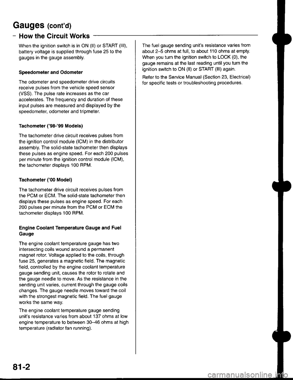
When the ignition switch is in ON (ll) or START (lll),
battery voltage is supplied through fuse 25 to the
gauges in the gauge assembly.
Speedometer and Odometer
The odometer and speedometer drive circuits
receive pulses lrom the vehicle speed sensor
(VSS). The pulse rate increases as the car
accelerates. The frequency and duration of these
input pulses are measured and displayed by the
speedometer, odometer and tripmeter.
Tachometer ('98-'99 Models)
The tachometer drive circuit receives oulses from
the ignition control module (lCM) in the distributor
assembly. The solid-state tachometer then displays
these pulses as engine speed. For each 200 pulses
per minute from the ignition control module (lCM),
the tachometer displays 100 RPM.
Tachometer ('00 Model)
The tachometer drive circuit receives pulses f rom
the PCM or ECM. The solid-state tachometer then
displays these pulses as engine speed. For each
200 oulses oer minute trom the PCM or ECM the
tachometer displays 1 00 RPM.
Engine Coolant Temperature Gauge and Fuel
Gauge
The engine coolant temperature gauge has two
intersecting coils wound around a permanent
magnet rotor. Voltage applied to the coils, through
fuse 25, generates a magnetic field. The magnetic
field, controlled by the engine coolant temperature
gauge sending unit, causes the rotor to rotate and
the gauge needle to move. As the resistance in the
sending unit varies, current through the gauge coils
changes. The gauge needle moves toward the coil
with the strongest magnetic tield. The fuel gauge
works the same way.
The engine coolant temperature gauge sending
unit's resistance varies from about 137 ohms at low
engine temperature to between 30-46 ohms at high
temperature (radiator fan running).
The fuel gauge sending unit's resistance varies from
about 2-5 ohms at full, to about 110 ohms at empty.
When you turn the ignition switch to LOCK (0), the
gauge remains at the last reading until you turn lhe
ignition switch to ON (ll) or START (lll) again.
Refer to the Service Manual (Section 23, Electrical)
for specific tests or troubleshooting procedures.
81'2
Page 1507 of 1681

Wiperffasher (contd)
- How the Circuit Works
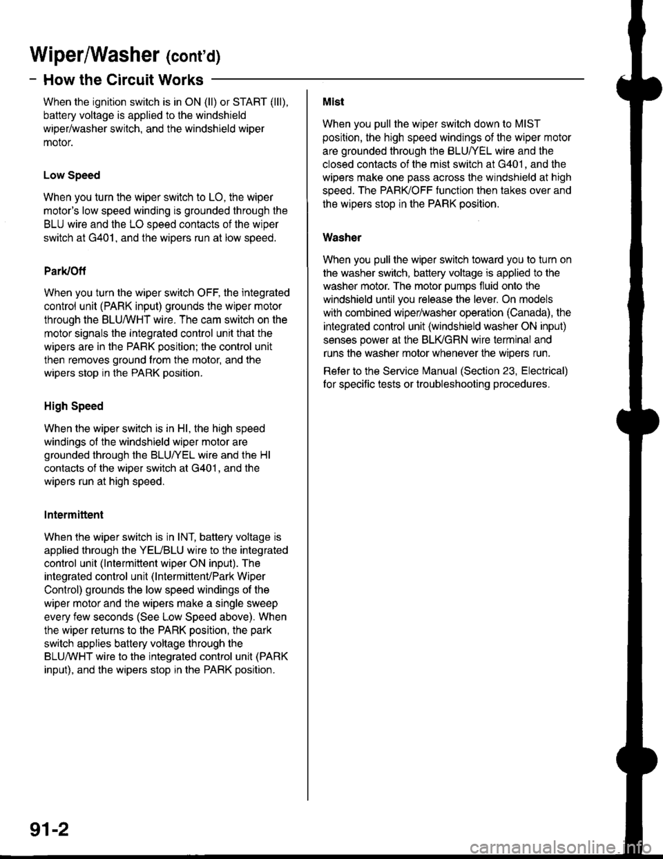
When the ignition switch is in ON (ll) or START (lll),
battery voltage is applied to lhe windshield
wiper/washer switch, and the windshield wiper
motor.
Low Speed
When you turn the wiper switch to LO, the wiper
motor's low speed winding is grounded through the
BLU wire and the LO speed contacts of the wiper
switch at G401, and the wipers run at low speed.
ParUOfi
When you turn the wiper switch OFF, the integrated
control unit (PARK input) grounds the wiper motor
through the BLUMHT wire. The cam switch on the
motor signals the integrated control unit that the
wipers are in the PARK position; the control unit
then removes ground from the motor, and the
wipers stop in the PARK position.
High Speed
When the wiper switch is in Hl, the high speed
windings ol the windshield wiper motor are
grounded through the BLUI/EL wire and the Hl
contacts of the wiper switch at G401 , and the
wipers run at high speed.
Intermittent
When the wiper switch is in lNT, battery voltage is
applied through the YEUBLU wire to the integrated
control unit (lntermittent wiper ON input). The
integrated control unit (lntermittenvPark Wiper
Control) grounds the low speed windings of the
wiper motor and the wipers make a single sweep
every few seconds (See Low Speed above). When
the wiper returns to the PARK position, the park
switch applies battery voltage through the
BLUMHT wire to the integrated control unit (PARK
input), and the wipers stop in the PARK position.
91-2
Mist
When you pull the wiper switch down to MIST
position, the high speed windings of the wiper motor
are grounded through the BLU//EL wire and the
closed contacts of the mist switch at G401, and the
wipers make one pass across the windshield at high
speed. The PABKOFF tunction then takes over and
the wrpers stop in the PARK position.
Washer
When you pull the wiper switch toward you to turn on
the washer switch, battery voltage is applied to the
washer motor. The motor pumps fluid onto the
windshield until you release the lever. On models
with combined wiper/washer operation (Canada), the
integrated control unit (windshield washer ON input)
senses power al the BLI(GRN wire terminal and
runs the washer motor whenever the wioers run.
Reter to the Service irlanual (Section 23, Electrical)
for specific tests or troubleshooting procedures.
Page 1596 of 1681

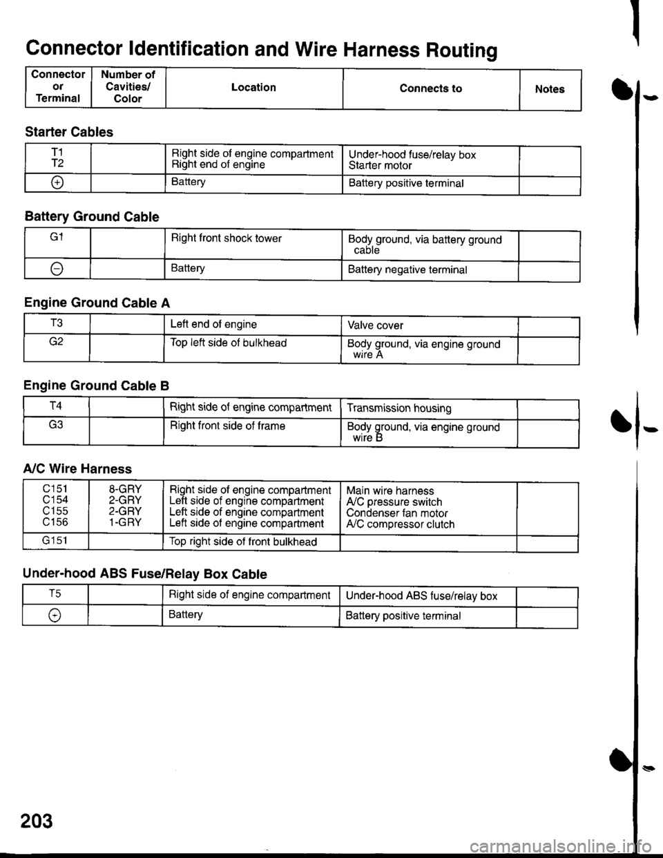
Connector ldentification and Wire Harness Routing
Connector
OT
Terminal
Number of
Cavities/
Color
LocationConnecls toNotesI
fl-
Starter Cables
T1
T2Right side of engine compartmentRight end of engineUnder-hood fuse/relav boxStarter motor
oBatteryBattery positive terminal
Battery Ground Cable
lRight front shock towerBodyground, via battery ground
ABatteryBattery negative terminal
Engine Ground Cable A
T3Left end of engineValve cover
Top left side ol bulkheadBody ground, via engine ground
Engine Ground Cable B
T4Right side of engine compartmentTransmission housing
Right front side of trameBody ground, via engine ground
wrre b
A,/C Wire Harness
Under-hood ABS Fuse/Relay Box Cable
203
c151
c'154utSc
u tco
8-GRY
2-GRY
2-GRY
1-GRY
Right side ol engine compartmentLeft side of engine compartmentLeft srde of engine compartmentLeft side of engine compartment
Main wire harness
A'lC pressure switch
Condenser tan motorA,/C compressor clutch
lrlclTop right side ot front bulkhead
T5Right side of engine compartmentUnderhood ABS fuse/relav box
\,BatteryBattery positive terminal