Page 898 of 1681

OpeningDragGheck
(Motor Removedl
Before installing the motor, measure the effort required
to open the glass using a spring scale as shown.
CAUTION: Wh€n using a spring scale, piotect the lead-
ing odge of the glass with a shop towel.
lf load is over 40 N 14 kgf, 9lbf), check side clearance
and glass height adjustment (see page 20-78).
Closing Force Check
(Motor Installedl'1. After installing all removed parts, have a helper hold
the switch to close the glass whjle you measure
{orce required to stop it. Attach a spring scale as
shown. Read the force as soon as the glass stops
moving, then immediately release the switch and
spflng scate.
CAUTION: When using a sp.ing scale, protect the
leading edge of the glass with a shop towel.
Closing Fo.ce: 200-29O N
{2O- 30 kst. 44-66 lbf)
SPRINGscAt_E
lf the force is not within specification, install a new
lock washer, adjust the tension by turning the mo
tor clutch adjusting nut, and bend the lock washer
against the motor clutch adjusting nut.
2.
LOCKWASHERReplace.
COUNTERcLocKwtsETo decrease
GLASS
t;-<
20-83
Page 905 of 1681

Moonroof
Opening Drag Check
(Motor Removedl
Before installing the motor, measure the effort required
to open the glass using a spring scale as shown.
CAUTION: When using a spring scale, protecl the lead-
ing edge ot the glass with a shop towel.
lf load is over 40 N (4 kgl, 9 lbfi, check side clearance
and glass height adjustment (see page 20-85)
Closing Force Check
{Motor Installed}
'1 . Alter installing all removed parts, have a helper hold
the switch to close the glass while you measure
Jorce required to stop it. Attach a spring scale as
shown. Read the lorce as soon as the glass stops
moving, then immediately release the switch and
spring scale.
CAUTION: when using a spring scale, protecl the
leading edge oI the glass with a shop towel.
Closing Force: 200-290 N
(20-30 ksf,44-66 lbtl
lf the force is not within specitication, install a new
lock washer, adiust the tension by turnlng the mo-
tor clutch adjusting nut, and bend the lock washer
against the motor clutch adjusting nut.
GLASS
\
clocKwrsE /?l a COUNTER-
To Increase \1, CLOCKWISE
force I lo oecreaseforce
20-90
--
Page 952 of 1681
Clock removal:
Carefully pry the clock at the lett edge, then pull it out.
Disconnect the connecto..
CONNECTOE
t:
o
Glove box removal:
1. Open the glove box.
2. Remove the screw, then remove the damper from
the glove box.
3. Remove the screw, then remove the glove box.
: Bolt, scrow
Al : Bolt, 2
A
ql
locations
B<: Scr€w, 1
)
il
4. Remove the damper and striker.
>: Nut, screw locations
A>: Nul, 1 B : Screw, 2
9;
E
e_)
5. Installation is the reverse of the removal procedure.
20-137
Page 954 of 1681
Replacement
1. To remove the dashboard, tirst remove the:
a Front seats {see page 20-'103)
a Front and rear consoles (see page 20-130)
a Oashboard lower cover {see page 20-133)
a Knee bolster (see page 20-134)
. Glove box (see page 20-137). Clock (see page 20-1371
. Moonroof switch (see page 20-136)
a Stereo radio/cassette (see page 20-134)
2. Lower the steering column (see section 17).
NOTE: To prevent damage to the steering column,
wrap it with a shop towel.
l ; Boh, nut locations
AA : Bolr, 28
: Nut, 2
8 x 1.25 mm22 N.m 12.2 kgl.n,16 tbf.ft)o21 13 N m 11.3 kgl m,
\€J' Prbl rll
_Urr'rr,t __)
STEERING JOINTCOVER
STEERING COLUMN
3. Remove the nuts, then remove the front passenger's
airbag bracket.
: Nut locations, 4
6 x 1.0 mm L9.8Nm
{1.o kgt m,7.2tbt.rrUFRONT PASSENGEB'SAIRBAG
PASSENGER'S
SRS MAINAIRBAG BRACKET
HARNESS
4. Disconnect the air mix control cable and connectors.
AIR MIX CONTROLCABLE
HEATERCONTROLPANELCONNECTORS
(cont'd)
20-139
Page 976 of 1681
J
Hatch Spoiler
Replacement
NOTE:
a Take care not to scratch the hatch.
a Open the hatch.
1. Remove the hatch side trim and hatch trim panel
{see page 20-148}.
2. Remove the nuts and disconnect the connector.
a: Nut locltion3,4
Type R Model:
a: f{ut locltlona, 4
Apply liquidthread lock.
6 x 1.0 mm9.8Nm
{1.0 kgf m,7.2 tbt.ltl ./CONNECTOR
3. Remove the hatch spoiler by turning the clip nut on
the left side counterclockwise.Apply liquidthread lock.
Installation is the reverse of the removal procedure.HATCH SPOILER
HATCH
6x1.0mm9.8 N.m11.0 kgt.m,?.2 tbt.ftl
4. Installation is the reverse of the removal procedure.
20-161
Page 1089 of 1681

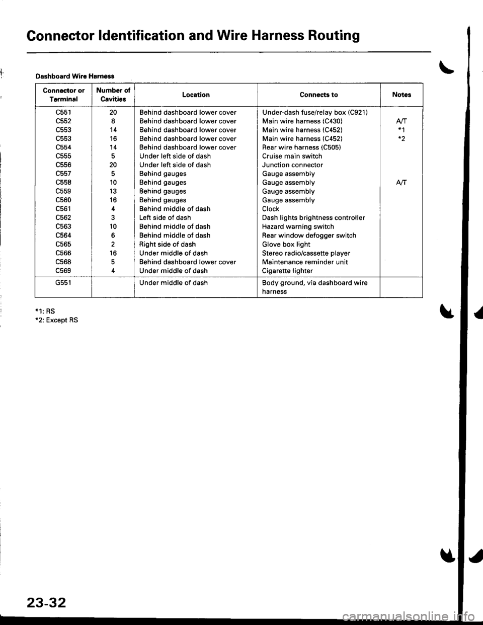
Connector ldentification and Wire Harness Routing
Dsshboard lvirc Harn€ss
Connoctor or
Terminal
Number ol
Cavitie3LocationCoDnects toNotes
c554
L55t'
c561
c562
c563
c564
c565
ucoo
uc06
c569
20
8
14
to
14
20
10
13
16
4
10
6
16
Behind dashboard lower cover
Behind dashboard lower cover
Behind dashboard lower cover
Behind dashboard lower cover
Behind dashboard lower cover
Under left side of dash
Under left side of dash
Behind gauges
Behind gauges
Behind gauges
Behind gauges
Behind middle of dash
Left side of dash
Behind middle of dash
Behind middle of dash
Right side of dash
Under middle of dash
Behind dashboard lower cover
Under middle of dash
Under-dash fuse/relay box (C921)
Main wire harness (C430)
Main wire harness (C452)
Main wire harness (C452)
Rear wire harness (C505)
Cruise main switch
Junction connector
Gauge assembly
Gauge assembly
Gauge assembly
Gauge assembly
Clock
Dash lights brightness controller
Hazard warning switch
Rear window defogger switch
Glove box light
Stereo radio/cassette player
Maintenance reminder unit
Cigarette lighter
At-|-
uc5 |Under middle of dashBody ground, via dashboard wire
narness
*1: RS12: Except RS
23-32
Page 1106 of 1681

T
I
1
J)
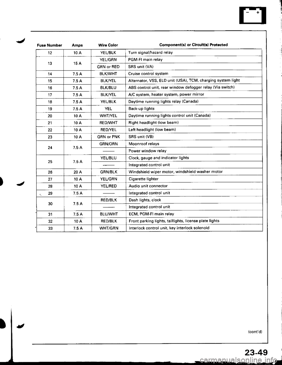
Fuso NumberWire ColorComponent{s} or Circuit(rl ftqt6cted
't210AYEUBLKTurn signal/hazard relay
15 AYEUGRNPGM-Fl main relay
GRN or REDSRS unit (VA)
147.5 ABLK/WHTCruise control system
15BLK/YE LAlternator, VSS, ELD unit (USA), TCM, charging system light
't67.5 ABLVBLUABS control unit, rear window defogger relay (Via switch)
117.5 ABLK//ELAVC system, heater system, power marror
187.5 AYEUBLKDaytime running lights relay (Canada)
197.5 AYELEack-up lights
2010 AWHT/YELDaytime running lights control unit (Canada)
2110 ARED/WHTRight headlight (low beam)
2210 ARE D|YE LLett headlight (low beam)
2310 AGRN or PNKSRS unit (VB)
247.5 AGRN/ORNMoonroof relays
Power window relay
7.5 AYEUBLUClock, gauge and indicator lights
Integrated control unit
2620AGRN/BLKWindshield wiper motor, windshield washer motor
10AYEUGRNCigarette lighter
2810AYEUREDAudio unit connector
29Integrated control unit
30RED/BLKDash lights, clock
Integrated control unit
317.5 A8LU/WHTECM. PGM-Fl main relav
10ARE D/BLKFront parking lights, taillights, license plate lights
7.5 AWHT/GRNInterlock control unit, key interlock solenoid
23-49
Page 1110 of 1681

J
)1 -
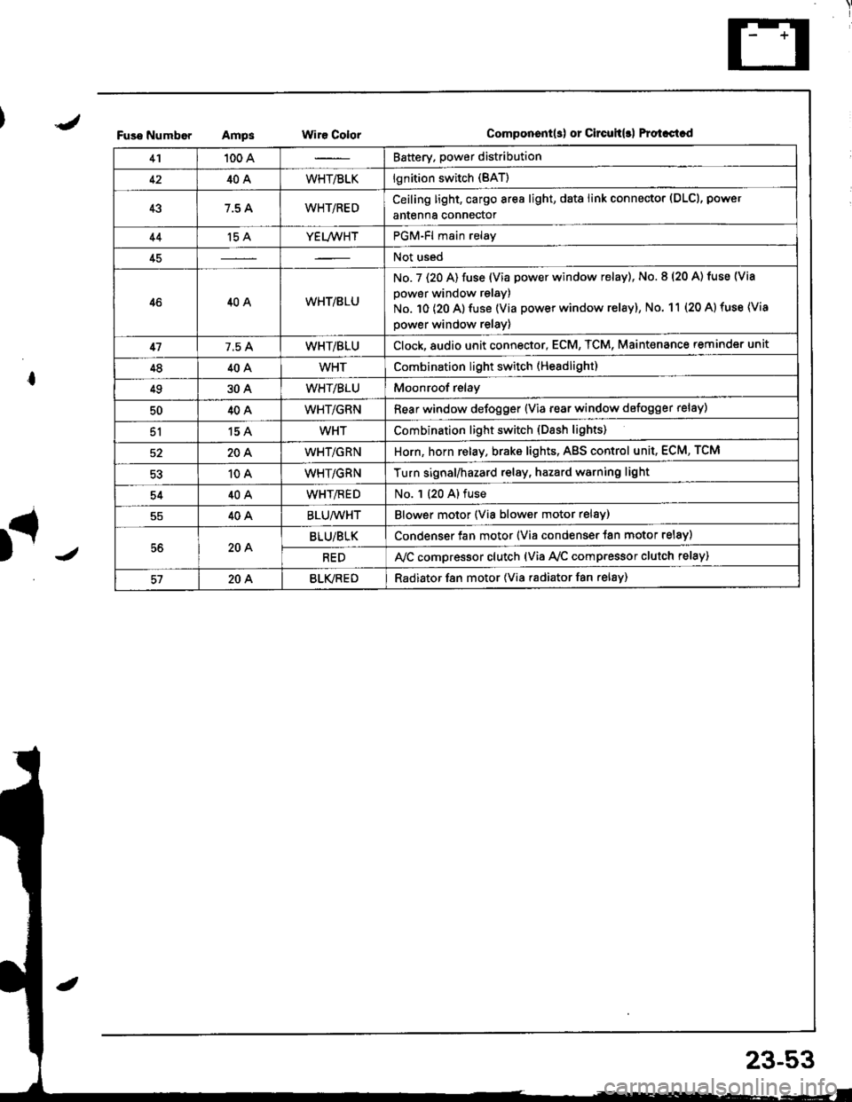
Fuso NumborAmpsWir€ ColorComponent(s) or Circuh(rl Protastcd
41100 ABattery. power distribution
4240AWHT/BLKlgnition switch (BAT)
437.5 AWHT/REDCeiling light, cargo area light, data link connector (DLCl, power
antenna connector
44't5 AYEL/WHTPGM-Fl main relay
45Not used
4640AWHT/8LU
No. 7 (20 A) fuse (Via power window relay), No. 8 (20 A) tuse (Via
power window relay)
No. 10 (20 A) fuse (Via power window relay), No. 11 (20 A) fuse (Via
power window relay)
417.5 AWHT/BLUClock,8udio unit connector, ECM, TCM, Maint€nance reminder unit
4840AWHTCombination light switch (Headlight)
4930AWHT/BLUMoonroof relay
5040AWHT/GRNRear window defogger {Via rear window defogger relay)
51154WHTCombination light switch (Dash lights)
20AWHT/GRNHorn, horn relay, brake lights, AgS control unit, ECM, TCM
10AWHT/GRNTurn signal/hazard relay, hazard warning light
5440AWHT/flEDNo. 1 (20 A) fuse
40ABLU/WHTBlower motor (Via blower motor relsy)
56204BLU/BLKCondenser fan motor (Via condenser {an motor relay)
REDA,/C compressor clutch (via Ay'c comp.essor clutch relay)
57204BLVREDRadiator f8n motor (Via radiator fan relay)
23-53