Page 66 of 1681

Valve Clearance
Adjustment (cont'dl
Adjust valve clearances on No. 1 cylinder.
Intske: 0.08 - 0.12 mm (0.003 - 0.005 inl
Exhaust: 0.15 - 0.20 mm (0.006 - 0.008 inl
Loosen the locknut and turn the adjusting screw
until feeler gauge slides back and forth with a slight
amount of drag.
7. Rotate the crankshaft 180' counterclockwise to
bring No. 4 piston to TDC. The "UP" mark should
be pointing straight down. Adjust valves on No. 4
cylinder.
Number 4 piston at TDC:
LOCKNUT9x0.75mm25 N.m {2.5 kgl.m, 18lbtft}
Tighten the locknut and recheck clearance again,
Repeat adjustment if necessary.
Rotate the crankshaft 180' counterclockwise(camshaft pulley turns 90'). The "UP" mark should
be on the exhaust side. Adjust valves on No,3 cylin-
der.
8. Rotate the crankshaft 180' counterclockwise to
bring No. 2 piston to TDC. The "UP" mark should
be on the intake side. Adjust valves on No. 2 cylin-
der.
Number 2 piston at TDC:
Number 3 Diston at TDC:
NOTE: Refer to page 6-31 when installing cylinder head
cover.
"UP" MARKS
"UP" MARKS
"UP" MARKS
Page 71 of 1681

\-a
I
I
{
. 6-9
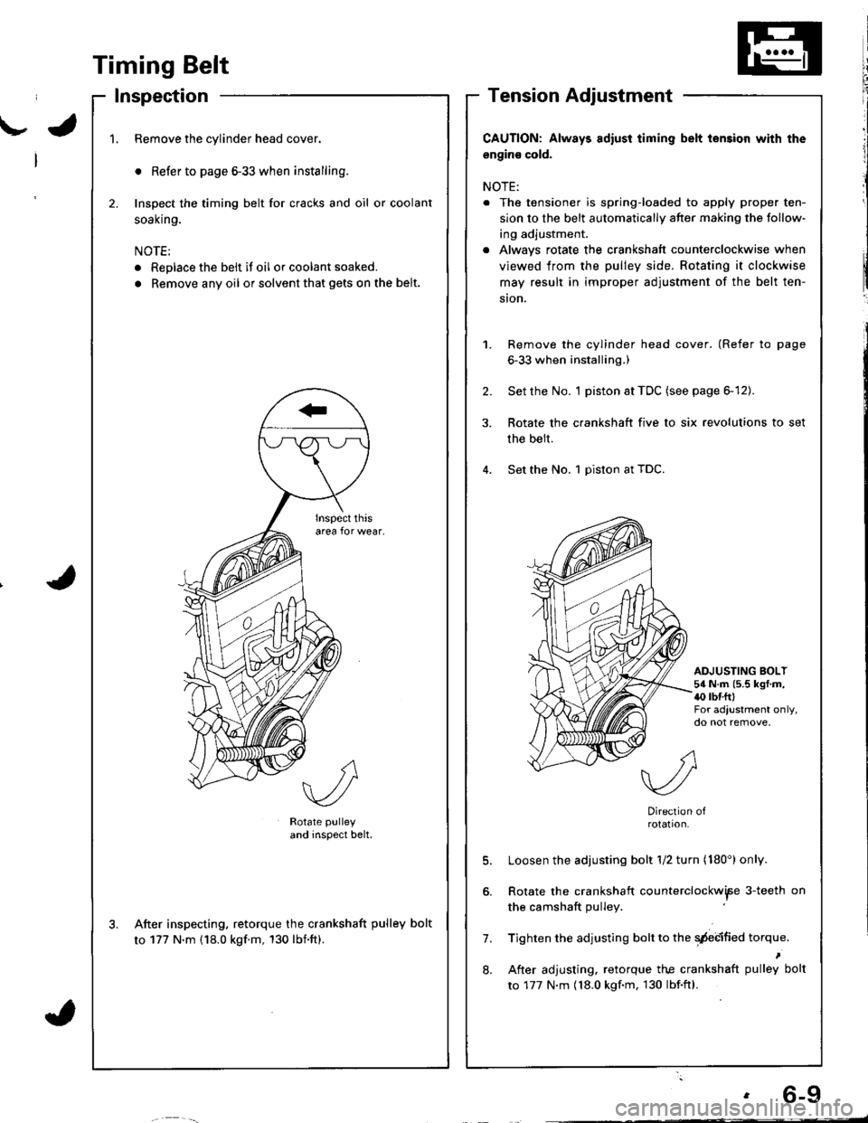
Timing Belt
Inspection
1.Remove the cylinder head cover.
o Refer to page 6-33 when installing.
Inspect the timing belt for cracks and oil or coolant
soal(n9.
NOTE:
. Replace the belt if oil or coolant soaked.
. Remove any oil or solvent that gets on the belt.
2.
Rotate pulley
and inspect belt.
After inspecting. retorque the crankshaft pulley bolt
to 177 N'm (18.0 kgf.m, 130 lbnft).
CAUTION: Always adiust iiming belt lension with the
engin€ cold.
NOTE:
. The tensioner is spring-loaded to apply proper ten-
sion to the belt automatically after making the follow-
ing adjustment.
. Alwavs rotate the crankshaft counterclockwise when
viewed from the pulley side. Rotating it clockwise
may result in improper adjustment of the belt ten-
ston.
Remove the cylinder head cover. (Refer to page
6-33 when installing.)
Set the No. I piston at TDC (see page 6-12).
Rotate the crankshaft five to six revolutions to set
the belt.
Set the No. 1 piston at TDC.
1.
2.
ADJUSTING BOLT54 N.m (5.5 kgf.m,{0 rbr.fttFor adjustment only,do not remove,
7.
8.
Direction ofrotation.
Loosen the adjusting bolt 1/2 turn (180') only.
Rotate the crankshaft counterclockwiFe 3-teeth on
the camshaft pulley
Tighten the adjusting bolt to the qdebified torque.
After adjusting. retorque the crankshaft pulley bolt
to 177 N.m {18.0 kgf.m, 130 lbf.ftl.
Page 170 of 1681

t'
Crankshaft
lnstallation
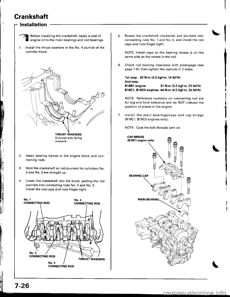
-Q Before installing the crankshaft, apply a coat of
E engine oilto the main bearings and rod bearings.
1. lnstall the thrust washers in the No. 4 iournal of the
cylinder block.
Grooved side facingoutwaro,
Insert bearing halves in the engine block and con-
necflng roos.
Hold the crankshaft so rod journals for cylinders No.
2 and No.3 sre straight up.
Lower the crankshaft into the block, putting the rod
iournals into connecting rods No.2 and No.3.
Installthe rod caps and nuts finger-tight.
No. 1No. 4
CONNECTING ROO
7-26
1.
Rotate the crankshaft clockwise, put journals into
connecting rods No. 1 and No.4, and install the rod
caps and nuts tinger-tight.
NOTEI lnstall caps so the bearing recess is on the
same side as the recess in the rod.
Check rod bearing clearance with plastigage (see
page 7-9), then tighten the capnuts in 2 steps.
lst step: 20 N.m (2.0 kgf m, 14 lbf.ftl
2nd step:
81881 engine:31 N.m (3.2 kgf.m, 23 lbf.ftl
818C1,818C5 enqines:44 N.m (4.5 kgf.m,33 lbt.ftl
NOTE: Reference numbers on connecting rod are
tor big-end bore tolerance and do NOT indicate the
position of piston in the engine.
Install the main bearings/caps and cap bridge(818C1, 818C5 engines only).
NOTE: Coat the bolt threads with oil
CAP BRIDGE{B18Cl engine onlyl
BEARING
MAIN BEARING
fi
U
t{
T
!+
T1
Page 172 of 1681
Crankshaft
Installation (cont'd)
I
I
t
l;I
I
fi,
\
10. Apply non-hardening liquid gasket to the block mat
ing surface of the oil pump, and install it on the
cylinder block.
11. lnstall the oil screen.
OIL PUMP:
Apply liquid gasket alongthe broken line.
5x1.0mm11N.m 11.1 kgt.m,8 tbtftl
GASKETReplace.
?,' /'\, /s.../
11 N.m {1.I kgf.m,
DOWEL PIN
o-ntNG
/\
/
':'
Apply engine oil.Replace.8 x 1.25 r\m24 N.m (2.4 kgt.m,17 tbf.ft)OIL PUMP
Apply liquid gasket on oil pump and right side
cover matinq areas as shown below.
CYLINDERBI_OCK Apply liquid gasket
RIGHT SIDECOVERApply liquid gasket
to lhese potnts-
to these points.
Install the oil pan gasket and oil pan.
NOTEr Use a new oil pan gasket.
Tighten bolts and nuts finger tight at six
shown below.
points as
Tighten all bolts and nuts stating from bolt O clock-
wise in three steps.
NOTE: Excessive tightening can cause distortion of
oil pan gasket and oil leakage.
Torqus: 12 N.m (1.2 kgf.m,8.7 lbf'ftl
14.
Page 181 of 1681

Oil Filter
Replacement (cont'd)
Install the oil filter by hand.
After the rubber seal seats, tighten the oil
clockwise with the special tool.
Tighten: 7/8 turn clockwise.
Tightening torque:22 N m (2.2 kgf m,'16 lbf ftl
tilte r
OIL FILTER WRENCH
8-8
Eight numbers (1 to 8) are printed on the surlace ol
the filter.
The lollowing explains the procedure for tightening
filters using these numbers.
1) Make a mark on the engine oil cooler (818c5
engine) or cylinder block (8188'1, 818C1 engines)
under the number that shows at the bottom of
the filter when the rubber seal is seated.
2) Tighten the filter by turning it clockwise seven
numbers Irom the marked point. For example, if a
mark is made under the number 2 when the rub
ber seal is seated, the filter should be tightened
until the number 1 comes up to the marked point
818C5 engine:
B1881, 818C1 engines:
Number when rubber
seal is seated.Number after tightening
MARK
MARK
Number when rubber
seal is seated
'I2345678
Number after tightening812561
5. After installation, fill the engine with oil up to the
specilied level, run the engine for more than 3 min-
utes, then check for oil leakage and oil level.
CAUTION: Installation using other than the above
procedure could result in serious engine damage
duo to oil leakage.
Page 205 of 1681
Inspection
Remove the timing belt (81881 engine: see page 6-10, B'l8Cl,818C5 engines: see page 6-48).
Tu.n the water pump pulley counterclockwise.Check that it turn freely.
Check for sign6 of seal leakage.
NOTE: A small amount of "weeping" trom thebleed hole is normal.
BLEED HOLE
Remove the timing belt (81881 engine: see page 6-
10,818C1, Bl8C5 engines: see page 6-48).
Remove the camshaft pulleys and the back cover(B'1881 engine: see page 6-20, 818C1, 818C5
engines: see page 6-60).
Remove the water pump by removing flve bolts.
NOTE: Inspect, repair and clean the O-ring groove
and mating surface with the cylinder block,
Replacement
6 x 1.0 mm12 N.m 11.2 kgt.m,8.7 tbf.tt)
4. Install the water pump in the reverse order ofremoval.
a Keep the O-ring in position when installing.a Clean the spilled engine coolant.
BLEED HOL€
10-1 1
Page 406 of 1681

Mainshaft Thrust Clearance
g. Slide the mainshaft base over the mainshaft.
Adjustment (cont'dl
/\
/-
MAINSHAFT BASE07GAJ - PG20130
Aftach the mainshaft holder to the mainshaft as fol-
lows:
NOTE:
o Eack-out the mainshaft holder bolt and loosen
the two hex bolts.
. Fit the holder over the mainshaft so its lip is
towards the transmission.
. Align the mainshaft holder's lip around the
groove at the inside of the mainshaft splines,
then tighten the hex bolts.
MAINSHAFT HOLDERbolt
MAINSHAFT BASE07GAJ - PG20130
Seat the mainshaft fully by tapping its end with a
plastic hammer.
Thread the mainshaft holder bolt in until it just con-
tacts the wide surface of the mainshaft base.
MAINSHAFT
f----M---E
|".ffi f\.xex
I \J \--l./ l/ Borrs
L- LE
\
MAINSHAfiHOLDER07GAJ - PG20110
13-40
Zerc a dial gauge on the end of the mainshaft.
Turn the mainshaft holder bolt clockwise; stop turn-
ing when the dial gauge has reached its maximum
movement. The reading on the dial gauge is the
amount of mainshaft end plav.
CAUTION: Turning the mainshaft holder bolt more
than 60 degrees after the needle of the dial gauge
stops moving may damage the transmission.
MAINSHAFT HOLDER07GAJ - PG20110
lf the reading is within the standard, the clearance is
correct.
It the reading is not within the standard, recheck the
shim thickness.
Standard: 0.11 - 0.18 mm (0.004 - 0.007 in)
DIAL GAUGE
Page 467 of 1681
![HONDA INTEGRA 1998 4.G Workshop Manual Troubleshooting Procedures
Checking the Diagnostic Trouble Code (DTC)
with an OBD ll Scan Tool or th€ Honda PGM Tester
When the TCM senses an abnormality in the input or output systems, the lD,] ind HONDA INTEGRA 1998 4.G Workshop Manual Troubleshooting Procedures
Checking the Diagnostic Trouble Code (DTC)
with an OBD ll Scan Tool or th€ Honda PGM Tester
When the TCM senses an abnormality in the input or output systems, the lD,] ind](/manual-img/13/6069/w960_6069-466.png)
Troubleshooting Procedures
Checking the Diagnostic Trouble Code (DTC)
with an OBD ll Scan Tool or th€ Honda PGM Tester
When the TCM senses an abnormality in the input or output systems, the lD,] indicator light in the gauge assembly will
blink. When the 16p Data Link Connector (DLC) (located under the dash on the passenger side) is connected to the OBD ll
Scan Tool or Honda PGM Taster as shown, the scan tool or tester will indicate the Diagnostic Trouble Code (DTC) when
the ignition switch is turned ON {ll}.
When the !r indicator light has been reported on, connect the OBD ll Scan Tool confirming to SAE J1978 or Honda PGM
Tester to the DLC (16P) behind the ashtray. Turn the ignition switch ON (ll) and observe the DTC on the screen ofthe OBD
ll Scan Tool or Honda PGM Tester. After determining the DTC, refer to the electrical system Symptom-to-Component
Chart on pages 14-54 and 14-55.
NOTE: SeetheOBDll ScanTool orHonda PGM Tester user's manual for specific instructions.
OBD-IlSCAN TOOL orHONDA PGM TESTER
Some PGM-Fl problems will also make the lol indicator light come on. After repairing the PGM-Fl system. disconnect the
BACK Up fuse (7.5 A) in the under-hood fuse/relay box for more than 10 seconds to reset the TCM memory, then recheck.
NOTE: Disconnecting the BACK UP fuse also cancels the radio anti-theft code, preset stations and the clock setting. Get
the customer's code number, and make note of the radio presets before removing the fuse so you can reset them
uJ trr
ulu
ai
14-50L
DATA LINK CONNECTOR (16P)
I
il
lt
rJq