Page 1274 of 1681
)
Switch Removal
CAUTION: Be carelul not to damage the heater con-
trol/center air vent.
1. Carefully pry the switch out oI the heater con-
trol/center air vent.
2. Disconnect the 6P connector from the switch.
Remove the indicator bulb (turn the socket 45o
counterclockwise), and remove the illumination bulb.
REAR WINDOWDEFOGGER SWITCH
INDICATOR BULB(o.84 W)
.l
Switch Test
NOTE: Be careful not to damage the heater con-
trol/center air vent.
'1. Carefully pry the switch out of the heater con-
trol/center air vent.
2. Check tor continuity between the terminals accord
ing to the table.
Terminal
pLN-_\BcDEF
PUSHEDo/:\-oo--o
o-
\:./
-o\:/
RELEASEDo-/:\_o
-oo-
\:,/
/:\\:./
I
6P CONNECTOR
REAR WINDOW DEFOGGER SWITCH
23-217
Page 1340 of 1681
Precautions/Procedures
Steering-related Precautions
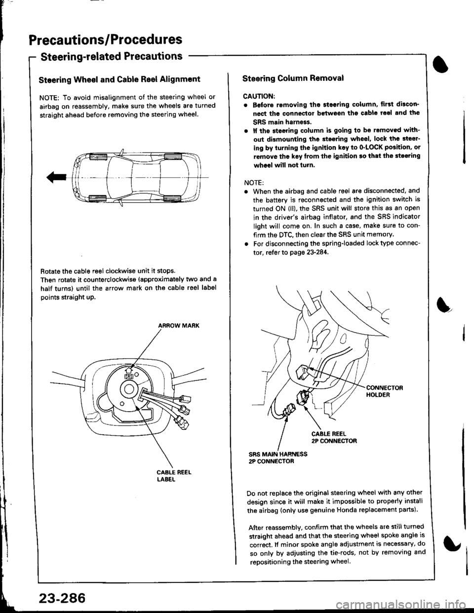
Steering Wheel and Gable Reel Alignment
NOTE: To avoid misalignment of the steering wheel or
airbag on reassembly. make sure the wheels are turned
straight ahead before removing the steering wheel.
Rotate the cable reel clockwise unit it stops.
Then rotate it counterclockwise (approximately two and a
half turns) until the arrow mark on the cable reel label
points straight up.
ARROW MARK
23-286
Steering Column Removal
CAUTION:
. Before romoving the steoring column, lirst di3con-
nect ths connector bctwoen tho csble rsal and the
SBS main harneEs.
. lf the steeting column is going to be rsmoved with-
out dismounting the steering wheel, lock the steer-
ing by iurning the ignition k6y to o'LOCK position' or
remove tho key lrom thc ignition ro that the steering
wheel will not turn.
NOTE:
When the airbag and cable reel are disconnected, and
the battery is reconnected and the ignition switch is
turned ON (ll), the SRS unit will store this as an open
in the driver's airbag inflator, and the SRS indicator
light will come on. In such a case, make sure to con-
firm the DTC, then clear the SRS unit memory.
For disconnecting the spring-loaded lock type connec-
tor, refer to page 23-284,
SRS MAIN HARNESS2P CONNECTOR
Do not replace the original steering wheel with any other
design since it will make it impossible to properly install
the airbag {only use genuine Honda replacement parts).
After reassembly. confirm that the wheels are still turned
straight ahead and that the steering wheel spoke angle is
correct, lf minor spoke angle adjustment is necessary, do
so only by adjusting the tie-rods, not by removing and
repositioning the steering wheel.
L
Page 1378 of 1681
Cable Reel
Replacement (cont'dl
CAUTION:
. Before installing the steering wheel, the lront
wheels should be aligned str8ight ahead.
. Be sure to install the harness wires so that they
are not pinched or interfering with other parts.
. After reassembly, confirm thal the wheels are
slill turned str8ight ahead and that the steering
wheel spoke angle is correst (road test). lf minol
spoke angle adjustment is necessary, do so only
by adiusting the tie-.ods, not by removing and
repositioning the steering wheel.
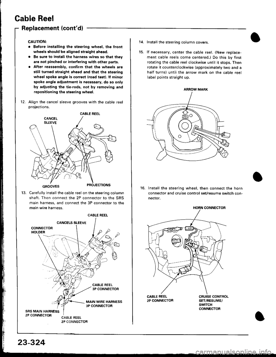
12. Align the cancel sleeve grooves with the cable reelprojections.
GROOVES
Carefully install the cable reel on the steering column
shaft. Then connect the 2P connector to the SRS
main harness, and connect the 3P connector to the
main wire harness.
CANCELS SLEEVE
CABLE REEL
13.
CABLE REEL
23-324
Install the steering column covers.
lf necessary, center the cable reei. (New replace-
ment cable reels come centered.) Do this by first
rotating the cable reel clockwise until it stops. Then
rotate it counterclockwise (approximately two and a
half turns) untll the arrow mark on the cable reel
label points straight up.
Install the steering wheel, then connect the horn
connector and cruise control sevtesume switch con-
necror.
15.
16.
CRUISE CONTROLSET/RESUME/swtTcHCONNECTOR
ARROW MARK
HORN CONNECTOR
Page 1383 of 1681
).1
Contents
How to Use This l\.4anual 1Circuit Schematics (see Circuit Index)Fuse/Relaylnformation 6ComponentLocation Photographs 201
Connector Cavity Numbers 202Connectorldentification 203
Ground-to-Components Index 6-6Wire Harness Routing 203Circuit ldentification lor ln-Line and Fuse Box Connectors
Circuit Index
Air conditionerAir delivery 61Blower controls 60Compressor controls 62Fans 63Anti-lock brake system (ABS) 44A/T gear position indicator 89Automatic transmission controls'98199 models 39'00 models 39-4Back-up lightsHatchback 110Sedan 110- 1Brake system indicator light
USA 71Canada 71-1Brake lightsHatchback 110-6Sedan 110-7Cargo area light (Hatchback) 114-3Ceiling light 114-2Charging system 22Cigarette lighter 155
Clock 154Condenser fan 63Console lights 114Cruise control 34Dash lights 1 14Daytime running lights 110-8Door open indicator 114-2Engine coolant temperature gauge 81Engine oil pressure indicator light 72Fog lights 110-14Front parking lights 110-11Front side marker lights 110-11Fuel gauge 81Fuse/relay boxUnder-dash 6Under-hood 6-3Under-hood ABS 6-5Gauges 81Glove box light 114Ground distribution 14Ground-to-Componentsindex 6-6Hatch open indicator '114-3
Hatch opener '134
Hazard warning lightsHatchback 'l l0-2Sedan 110-4Headlights 1'10-8Headlight switch 100HeaterAir delivery 61Blower controls 60Fanswith A,/C 63without A,/C 63-2Horns 40lgnilion key reminder 73lgnition system 20
204
lmmobilizer system ('00 model) 132lndicators 80Integrated control unit 70Interlock system'98199 models 138'00 models 138-1License plate lightsHatchback 110-12Sedan 110-13Lights-on reminder 73Low fuel indicator light 74l\,4aintenance reminder light 83l\iloonroof 122Odometer 81-1Power antenna 151Power distributionBattery to ignilion switch, fuses, and relays
Fuses to relays and components 10-2Power door locksHatchback '130
Sedan 130-2Power mirrorsHatchback 141Sedan 141-1Power windowsHatchback 120Sedan 120-2Programmed fuel injection system (PGM-Fl)'98199 models 23'00 models 24Radiator fanwith tuC 63without A,/C 63-2Rear parking lightsHatchback 110-12Sedan 110- 13Rear window defogger 64Seat belt reminder 73Security system 133Speedometer Il-1Spotlights 114-2Starting syslemAutomalictransmission 21l\.4anualtransmission 21-1Stereo sound system 150Supplemental restraint system (SRS) 47Tachometer 81- 1TaillightsHatchback 110-12Sedan 110-13Trailer lighting conneclor 118Trunk lid open indicator 114-3Trunk light (Sedan) 114-3Turn signal lightsHatchback 110-2Sedan 110-4Vehicle speed sensor (VSS) 33Wiper/washerFront 91Rear 92
10
).1
I
Xr
12Fg oAmerican Honda Motor Co., Inc. - All Rights Reserved Service Communications 275 pages
Page 1387 of 1681
How To Use This Manual
Power Distribution Schematics
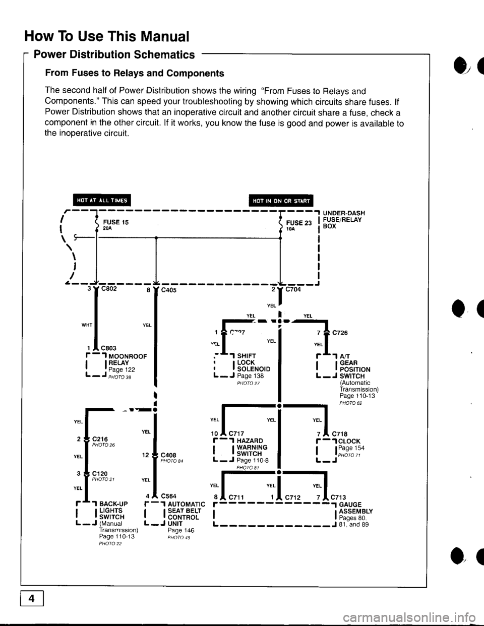
From Fuses to Relays and Components
The second half of Power Distribution shows the wiring "From Fuses to Relays and
Components." This can speed your troubleshooting by showing which circuits share fuses. lf
Power Distribution shows that an inoperative circuit and another circuit share a fuse, check a
component in the other circuit. lf it works, you know the fuse is good and power is available to
the inooerative circuil.
ol
I
I
\
FUSE 15204
UNDER-OASHFUSE/RELAYBOXFUSE 2310A
\
I
/
O(
.II
l-- -
1?c-.7
.:r- I YEL
:*.l sHrFTr I LOCKI I SOLENOIDL- J Page 138PHOfO2T
I lFEt[,o'
L -J SWITCH(AutomaticTransmission)Page 110-13
-l PHaro 62
IYEL Iz I czrar -.lclocK
, l"i1:"':oL-Jc408
r-.l HAZARD
I t3'�S[t''i"L- J Page 110,8
:I-c564
1 AUTOMATIC
I SEAT BELTI CONTROLJ UNITPage 146
YEI
r
IL
c7t3
I l5"f,TE'"L -J (N,4anualTransmission)Page 110-13
r------
I ti:*'"T8*L____________J 81. and 89
3rc802 8
I
"* | YEL
I
', I "ro.f - 1 MooNRooF
| 13"'^TI",L-J,iiio'i'
2 3 C216
3 g cl20
ol
Page 1402 of 1681
FuserRelay I nformation
- Under-dash Fuse/Relay Box (cont'd)
Fuse
Number
i R - HEAD LTGHT ii LOWBEAM i
Fuse NameAmpsPageComponent or Clrcull Protected
10 ii Right headlight
! L _ HEAD LIGHT I
I row eenu I
10 i110-8Left headlight
(sRs)I roSRS unit
24 I P/IV RELAY IPower window relav. Moonroof
l(suNRooFBELA!l
7.5 I 10-4 |
tl
25 | METER | 7.5 | 10-5 |
rttl
Clock, Gauge assembly, Integrated control unit, Interlock
system, Maintenance reminder unit
Front wiper/washer26 i FR W|PER
I FR WASHEB
27 | crcnnerre
i LTGHTER
28 i RApro i10 i
Cigarette lighter
10-s iStereo radio/cassette player
30 I INSTRUMENT
I LIGHTS
2e | (RR Foc LtcHT) | z.s !
| 7.5 |
tl
3'1 i STARTER STGNAL21,21-1 1
32 i LTCENSE LtcHrS Ii TAIL LIGHTS ii 1001 i
| (rNrER LocK uNrr)l
II
114 | Dash & console lights, Integrated control unit
ECM or PCM, Integrated control unit, PGM-FI main relay
License plate lights, Parking lights, Taillights
Interlock system
6-2
Page 1404 of 1681
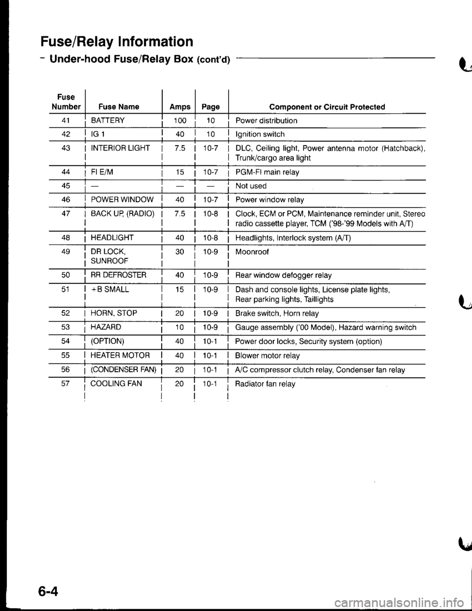
Fuse/Relay I nformation
- Under-hood Fuse/Relay Box (cont'd)
Fuse
NumberFuse NameAmpsPage
BATTERY
I INTERIOR LIGHT
I
1 7.5 110-7 I
I
Component or Circuil Protected
Power distribution
lgnition switch
DLC, Ceiling light, Power antenna motor (Hatchback),
Trunk/cargo area light
47
I Fl E/lvl
POWER WINDOW
I BACK UP (RADTO)
I
15 | 1 0-7 I PGM-FI main relay
Not used
Power window relay
Clock, ECM or PCM, Maintenance reminder unit, Stereo
radio cassette player, TCM ('98-'99 Models with A'/T)
7.5 |10-8
I HEADLIGHT| 40 | 10-8 | Headlights, Interlock system (A/T)
49i DR LOCK,
i suNRooF
10-9 i Moonroof
I
I RR DEFROSTER
+ B SMALL
I Rear window detogger relay
I Dash and console lights, License plate lights,
I Rear parking lights, Taillights
I HORN, STOP
i HAZARD
10-9 | Brake switch, Horn relay
i Gauge assembly ('00 Model), Hazard warning switch
40 | to t I Power door locks, Security system (option)
I HEATER MOTOR II t 0-1I Blower motor relay
20 I 10-1 ; A,/C compressor clutch relay, Condenser fan relay
i Radiator fan relay1 0-1
6-4
Page 1413 of 1681
UNDER.DASHFUSE/RELAYBOXFUSE 25IIETER?.5A
FUSE 26
FR WASHEF204
\
I
I
t
I
I
INTEGRATEDCONTROL UNITPage 70
- - -Y iliirinars r-arYEL/BLU I pHoro,4
't0--i:--L
-
--'-r--
,c;% : " lf "tio$, ir':ii
i 'r.u".u | :
:ii
il;
i 'I"0,, I, r--1
:ll:
i !.--l iI SHIFT LOCK, SoLENOIO ;: Paqe 13B ( 98-99) ,; or 138 1 ('00)I PHQ|O 124 ;------o,n -----,
Czt38
t-
":-[ "::]
*-' 33r'$$'o"
-"'",,*j*"
I
i'sn+.1* !Pase 1ss
I
I
,T'*' I
-u.,*""1t-**" ,Iu*c55t 1|' Cs57 4
I
IL--J L-------JCLOCK GAUGEPage 154 ASSEMBLYPages 80, 80-2,81, 83, and 89PHOIO 47
(Not 5Used)
GBN/BLK
?
I
I
c559.l
I
I
1 r-1 r--1
I
Il1
WIND.SHIELDWIPERMOTORPage 91-1
t--J L--JMAINTENANCE COMBI.REMINDER NATIONUNIT WIPERPage 83 SWITCHpHoro s2 Page 91
STEREORADIO/CASSETTEPLAYERPage 150
(cont'd)
10-5