Page 1136 of 1681
1.Remove the dashboard lower cover and knee bolster(see page 23-71],, then disconnect the 2P connector
from the switch.
Check for continuity between the terminals accord-
ing to the table.
2.
3.ll necessary, replace the switch or adiustthe switch
position (see section 12).
Terminal
cr,t"hP;i
-_\B
RELEASED
PUSHEDoo
Clutch lnterlock Switch TestStarter Solenoid Test
1. Check for continuity between the terminals accord-
ing to the table.
HOLD_ IN COIL
23-79
I
/
-
I
-a
Coil
Teminalt\4sHousing
HOLD INO-o
PULL-INo-o
PULL_ IN COIL
Page 1138 of 1681
I
,.
u
J
/
Starter Overhaul
CAUTION: Disconnect th€ banery negative cable botore
removing the starter.
NOTE: The original radio has a coded theft protection
citcuit. Be sure to get the customer's code number before- disconnecting the baftery.- removing the No. ,17 (7.5 A) fuse from the under-hood
fuse/relav box.- removing the radio.
After service, reconnect power to the radio and turn it
on. When the word "CODE" is displayed, enter the cus-
tomer's 5-digit code to restore radio operation.
BRUSH HOLDERTest, page 23-82
BRUSHInspectaon, page 23-82
SOLENOID HOUSING
STEEL BALL
install steel ballfrom clutch side.
-.''.!k.��rt{l{
MOLYBDENUMDISULFIDE
OVERRUNNING CLUTCH ASSEMBLYInspection, page 23-85
PINTON GEAB IDLER GEAR
\
HARNE'SBRA.KET
-\l
-
^,1FIELD WINDING/ 'A \
f:$i:y5J*"""
*\s
SOLENOIDPLUNGER
STARTEBSOLENOID
inspection,
BRUSH HOLDER
Test, page 23-79
OVERRUNNINGCLUTCH ASSEMBLY
ARMATURE
O-RING
COVER
I
6
%
-@t
MOLYBDENUMDISULFIDE
END COVER
GEAR HOUSING
Page 1142 of 1681
BRUSHES
Startel Field Winding Test
Check for continuity between the brushes. lf there's
no continuity. replace the armature housing.
Check for continuily between each brush and the ar-
mature housing (ground). lf there is continuity,
replace the armature housing.
Overrunning Clutch InsPection
Slide the overrunning clutch along the shaft.
Does it move freely? It not, replace it.
Rotate the overrunning clutch both ways.
Does it lock in one direction and rotate smoothly in
reverse? It it does not lock in either direction or it
locks in both directions, repl8c€ it,
lf the starter drive gear is worn or damaged, replace
the overrunning clutch assembly; the gear is not
available separately.
Check the condition ot the flywheel or torque con-
vener ring gear it the starter drive gear teeth are
damaged.
/
J
CLUTCH G€AR
DRIVE GEAR
23-85
l'l- ,-----_ -'l
Page 1214 of 1681
M
lgnition switch at
START iIII)
Check for voltage to ground:
There should be battery voltage.
Blown No.31 (7.5 A) fuse in the
under-dash fuse/relay box
Faulty clutch interlock switch or
starter cut relay (M/T)
Faulty neutral position switch (A/T)
An open in the wire
2D
lgnition switch ON {ll).
brake fluid reservoir
full, and parking brake
tever oown
Connect to ground: Brake
system light should come on.
. Blown brake system light. An open in the wire
Bulb Check System (brake system light)
No. Terminal Test conditionTost: Desiled resultPossiblo cause if lesult is not obtained
)
)
23-157
Page 1280 of 1681
Terminal
;'..b;--\BcD
OFFCF--o
OPENO--_oo--_o
CLOSEo-_O
o-o
Switch Test
Remove the dashboard lower cover.
Carefully pry the switch out of the left side ajr ventpanel, then disconnect the 4P connector and remove
the switch.
Check for continuity between the terminals in each
switch position according to the table.
MOONROOF SWITCH
1.
2.
Motor Test
Remove the headliner (see section 20).
Disconnect the 2P connector from the moonroof
moror.
Check the motor by connecting power and ground
according to the table.
NOTE: Motor clutch test is in section 20.
{Hatchbackl {Sedanl
View from terminal side
lf the motor tails to run or does-: run smoothly,reptace rt.
)
)
Terminal
Conditbn - ll\B
OPENoo
CLOSEoo
,l
\{J\,, CLOSE
?
IOPENOFF
23-223
Page 1311 of 1681

t
t;
i'l
I
dil
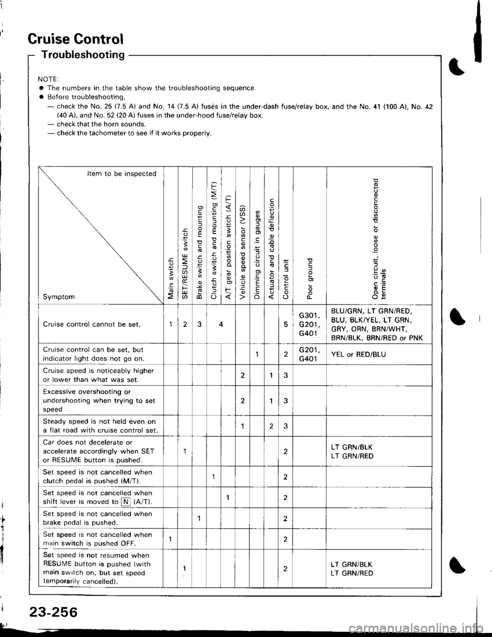
Gruise Gontrol
Troubleshooting
NOTE:
a The numbers in the table show the troubleshooting sequence.
a Belore troubleshooting,- check the No. 25 (7.5 A) and No. 14 (7.5 A) fusds in the under-dash fuse/relay box. and the No. 4l (100 A), No. 42(40 A), and No. 52 (20 A) fuses in the under-hood fuse/relay box.- check that the horn sounds.- check the tachometer to see if it works properly.
Item to be inspected
Symptom
c
:3
UJ
lU)(r
F(t
)
E
c
.
F
=
.g
E
-c
!-
Io
F
3
E
o)F
u)U'
co
_q.9-c
o)f,
ol
;l
E
.Eo
F
E
_9
)a
o
o-
o
c
.2
'::-c
OE
Cruise control cannot be set.15
G301
G201
G40't
BLU/GRN, LT GRN/RED.
BLU, BLKTYEL, LT GRN.
GRY, ORN, BRNiWHT,
BRN/BLK, BRNi RED or PNK
Cruise control can be set, but
indicator light does not go on.1G201
G401YEL or RED/BLU
Cruise speed is noticeably higher
or lower than what was set.1
Excessive overshooting or
undershooting when trying to set
speed
'I
Steadv soeed is not held even on
a flat road with cruise control set.1J
Car does not decelerate or
accelerate accordingly when SET
or RESUME button is pushed.
1LT GRN/BLK
LT GRN/RED
Set speed is not cancelled when
clutch pedal is pushed (M/T).1
Set speed is not cancelled when
shift lever is moved ro N (A/T).I
Set speed is not cancelled when
brake pedal is pushed.12
Set speed is not cancelled when
main switch is pushed OFF.
Set speed is not resumed whenRESUME button is pushed (with
main switch on, but set speedtemporarily cancelled).
2LT GRN/BLK
LT GRNiRED
23-256
Page 1313 of 1681

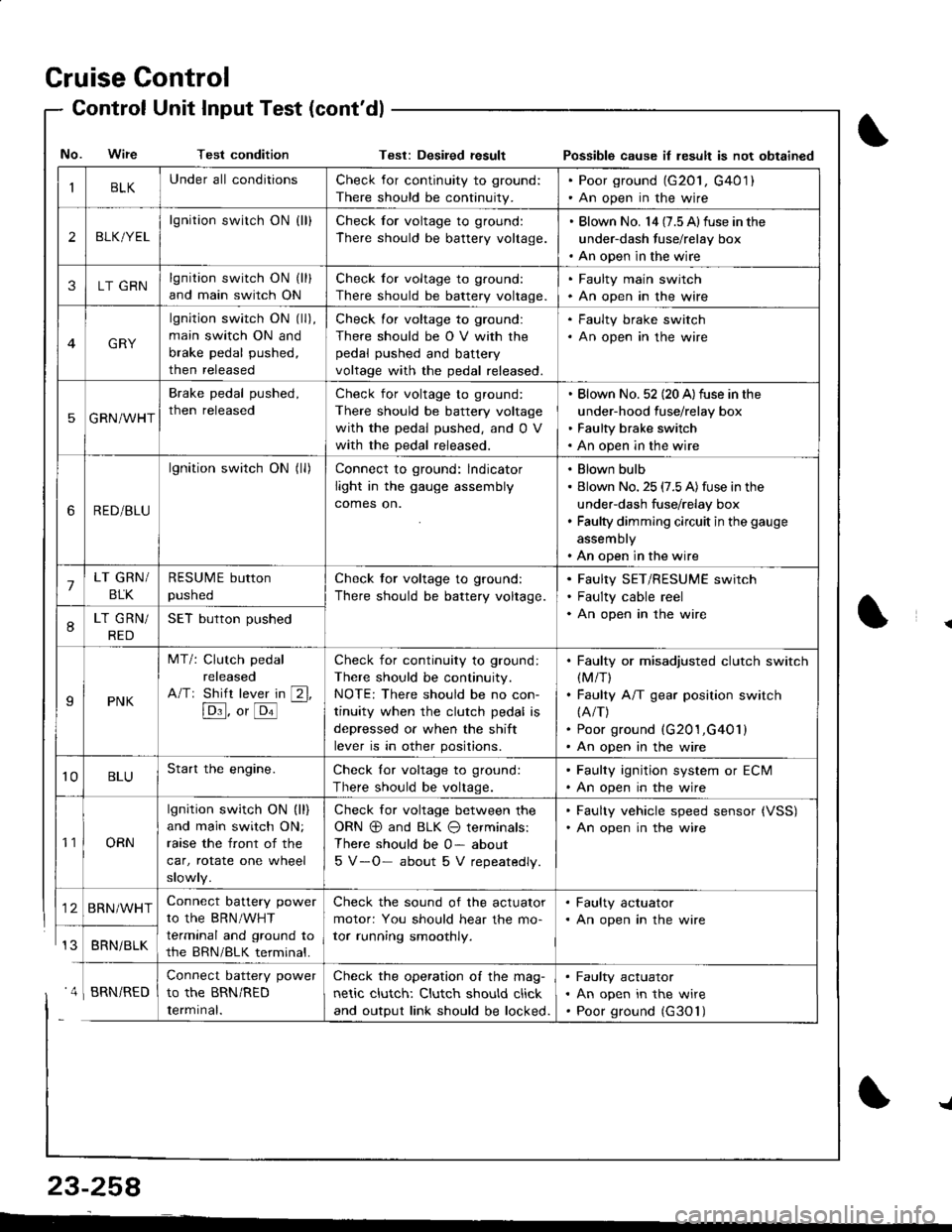
Cruise Control
- Control Unit InputTest(cont'dl
IBLKUnder all conditionsCheck for continuity to ground:
There should be continuity.
. Poor ground (G20l, G401). An open in the wire
2BLK/YEL
lgnition switch ON {ll}Check for voltage to ground:
There should be battery voltage.
. Blown No. l4 (7.5 Alfuse in the
under-dash fuse/relay box. An open in the wire
3LT GRNlgnition switch ON (ll)
and main switch ON
Check for voltage to ground:
There should be battery voltage.
. Faulty main swjtch. An open in the wire
GRY
lgnition switch ON (ll),
main switch ON and
brake pedal pushed,
then released
Check for voltage to ground:
There should be O V with the
pedal pushed and battery
voltage with the pedal released.
. Faulty brake switch. An open in the wire
5GRN/WHT
Brake pedal pushed,
then released
Check for voltage to ground:
There should be battery voltage
with the pedal pushed, and 0 V
with the pedal released.
Blown No. 52 (20 A)fuse in the
under-hood fuse/relay box
Faulty brake switch
An open in the wire
6RED/BLU
lgnition switch ON (ll)Connect to ground: lndicator
light in the gauge assembly
comes on.
Blown bulb
Blown No. 25 (7.5 A)fuse in the
under-dash fuse/relay box
Faulty dimming circuit in the gauge
assembly
An open in the wire
7LT GRN/
BLK
RESUME button
pushed
Check tor voltage to ground:
There should be battery voltage.
Faulty SET/RESUME switch
Faulty cable reel
An open in the wire8LT GRN/
RED
SET button pushed
IPNK
MT/: Clutch pedal
released
A/Tr Shift lever in [2l,
[Dl]. o, [o'l
-
Check for continuity to ground:
There should be continuity.
NOTE: There should be no con-
tinuity when the clutch pedal is
depressed or when the shift
lever is in other positions.
Faulty or misadjusted clutch switch(M/T)
Faulty A/T gear position switch(A/T)
Poor ground (G201,G401)
An open in the wire
't0BLUStart the engine.Check lor voltage to ground:
There should be voltage.
. Faulty ignition system or ECM. An open in the wire
't1ORN
lgnition switch ON (ll)
and main switch ON;
raase the front of the
car, rotate one wheel
slowly.
Check for voltage between the
ORN @ and BLK O terminals:
There should be 0- about
5 V-O- about 5 V repeatedly.
. Faulty vehicle speed sensor {VSS). An open in the wire
BRN/WHTConnect battery power
to the BRN/WHT
terminal and ground to
the BRN/BLK terminal.
Check the sound of the actuator
motor: You should hear the mo-
tor running smoothly.
. Faulty actuator. An open in the wire
BRNi BLK
Connect battery power
to the BRN/RED
Iermrnal.
Check the operation of the mag-
netic clutch: Clutch should click
and output link should be locked.
Faulty actuator
An open in the wire
Poor ground (G30'l)
No. Wire Test conditionTest: Desiled result Possible cause il lesult is not obtained
' 4 I BRN/RED
{
{
23-258
-L
Page 1317 of 1681
Gruise
- Brake
Control
Switch TestClutch Switch Test {M/T}
1. Disconnect the 4P connector from the switch.
4P CONNECTOR
2.Check lor continuity between the terminals accord
ing to the table.
3. lf necessary, replace the switch or adjust pedal
height (see section 19).
AB-\f:t-!l-'tr
I
f--! I
PEDAL
Terminal
;"r"*--__\BcD
R E LEA SEDCF--o
PUSH E Do---o
'1. Disconnect the 2P connector trom the switch.
2P CONNECTOR
CLUTCH SWITCH
CLUTCH PEDAL
Check for continuity between the terminals accord-
ing to the table.
3. lf necessary, replace the switch or adjust pedal
height (see section 12).
Terminal
.t"i*"1
I
RETEASEDoo
PUSHED
\
23-262