Page 1083 of 1681

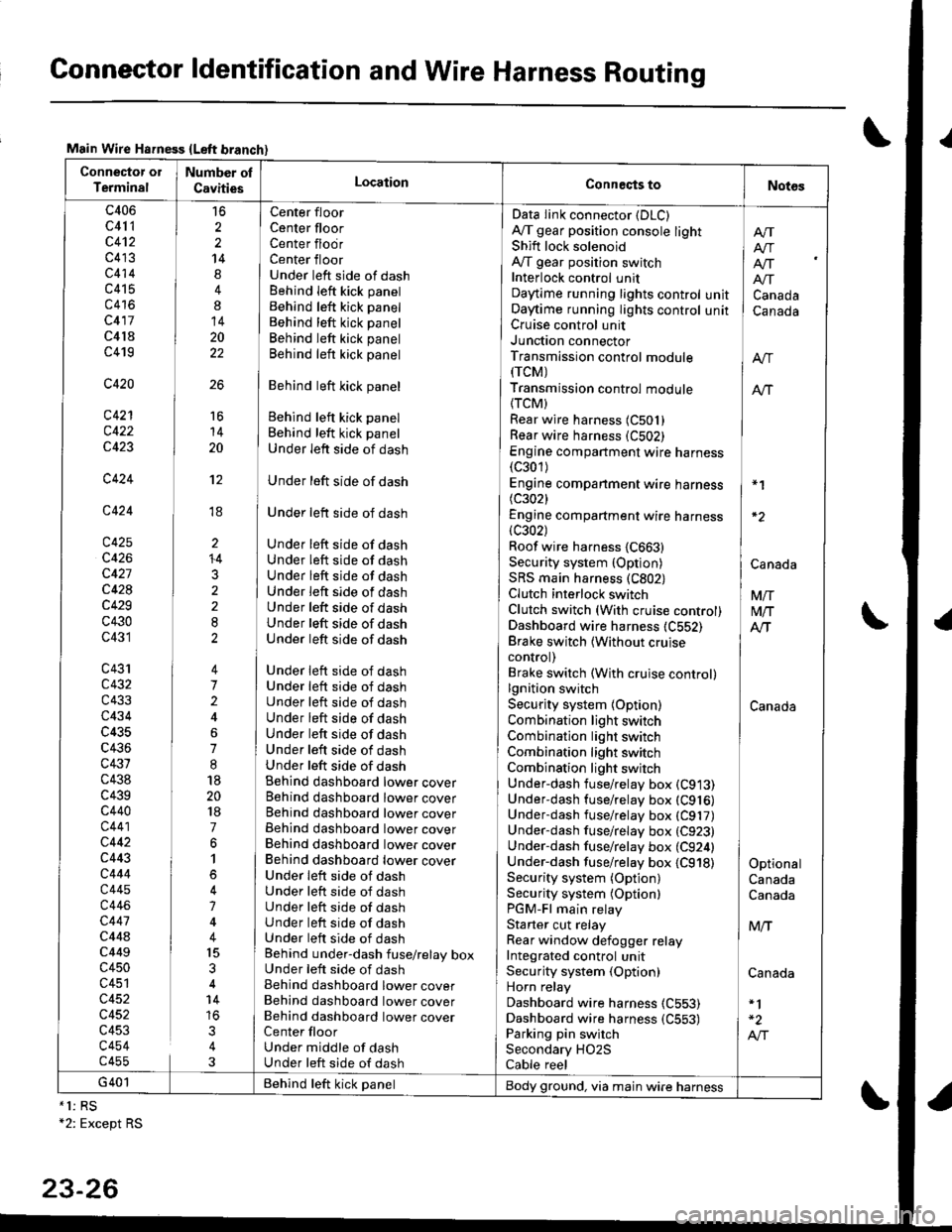
Connector ldentification and Wire Harness Routing
Main Wire Hsfness {Left branch}
Connector ol
TerminalNumber ol
CavitiesLocationConneqts toNot6s
c406
c41 1
c4't2
c413
c414
c415
c416
c417
c4l8
c419
c420
c421
c422
c423
c424
c424
c425
c426
c427
c428
c429
c430
c431
c43'rc432
c433
c434
c435
c436
c431
c438
c439c440
c441
c442
c443
c444
c445
c446
c447
c44ac449
c450
c451
c452
c452
c453
c454c455
16
2
2
14
4
8
14
20
22
26
Center floor
Center floorCenter flodrCenter floorUnder left side of dashBehind Ieft kick panel
Behind left kick panel
Behind left kick panel
Behind left kick panel
Behind left kick panel
Behind left kick panel
Behind left kick panel
Behind left kick panel
Under left side of dash
Under left side of dash
Under left side of dash
Under left side of dashUnder left side of dashUnder left side of dashUnder left side of dashUnder left side of dashUnder left side of dashUnder left side of dash
Under left side of dashUnder left side of dashUnder left side of dashUnder left side of dashUnder left side of dashUnder left side of dashUnder left side of dashBehind dashboard lower coverBehind dashboard lower coverBehind dashboard lower coverBehind dashboard lower coverBehind dashboard lower coverBehind dashboard lower coverUnder leit side of dashUnder left side of dashUnder left side of dashUnder left side of dashUnder left side of dashBehind under-dash fuse/relay boxUnder left side of dashBehind dashboard lower coverBehind dashboard lower coverBehind dashboard lower coverCenter floorUnder middle of dashUnder left side of dash
Data Iink connector (DLC)
A,/T gear position console lightShift lock solenoidAy'T gear position switchInterlock control unitDaytime running lights controlOaytime running lights controlCruise control unitJunction connectorTransmission control module(rcM)
Transmission control module
{TCM)Rear wire harness (C501)
Rear wire harness (C502)
Engine compartment wire harness(c301)
Engine companment wire harness I *1
(c3021 IEngine compartment wire harness(c302) lRoof wire harness {C663} |Security system {Option) | CanaAaSRS main harness (C802) |Clutch interlock switch I VnClutch switch (With cruise control) M/TDashboard wire harness (C552) AlTBrake switch lwithout cruise Icontrol) |Brake switch (With cruise control)lgnition switch ISecurity system {Option) CanadaCombination light switch /Combination light switch ICombination light switchCombination light switchUnder-dash fuse/relay box (C913)
Under-dash fuse/relay box (C916)
Underdash fuse/relay box (C917)
Under-dash fuse/relay box (C923)
Under-dash fuse/relay box (C924) |Under-dash fuse/relay box {C918) I OptionalSecurity system (Option) CanadaSecurity system (Optionl CanadaPGM-Fl main relayStarter cut relay ] M,.fRear window defogger relay IIntegrated control unitSecurity system (Option) CanadaHorn relay
Dashboard wire harness (C553)
Dashboard wire harness {C553) | -2
Parking pin switch I A,"ISecondary HO2S
Cable reel
Afi
I Atr
lf[
unit ] Canadaunit I Canada
16
14
20
't2
ti
I'
li
ll
li
+4
3
G401 Behind teft kick panelBody ground, via main wire harness*1: RS+2: Except RS
23-26
Page 1109 of 1681
Fuses
Under-hood Fuse/Relay Box
AITEFNATOR[To .ngine wiro hrrn83 1T101)l
BATTERYlTo stano. csblca lTlll
C!104 [To condenso] fan relayl
*: Not u6edclutch l.hyl
NOTE: View from the backside of the under-hood fuse/relav box.
ClOg [To main wiro ha]ne3s {C215ll
C!107 [To blow.r motor r.l.yl
C908 [To m.in wiro h.rn.$ (C2l7ll
rr17
LI
Fl51
LI
rl56
lJ
rr51
IJ
C905 [To A/C compr.ssor C9O6 [To radirto] fan
23-52
Cltl1 lTo main wire harness lc218ll: USA
C€10 [To mrin wir. hlrnoit lC216ll
Page 1110 of 1681

J
)1 -
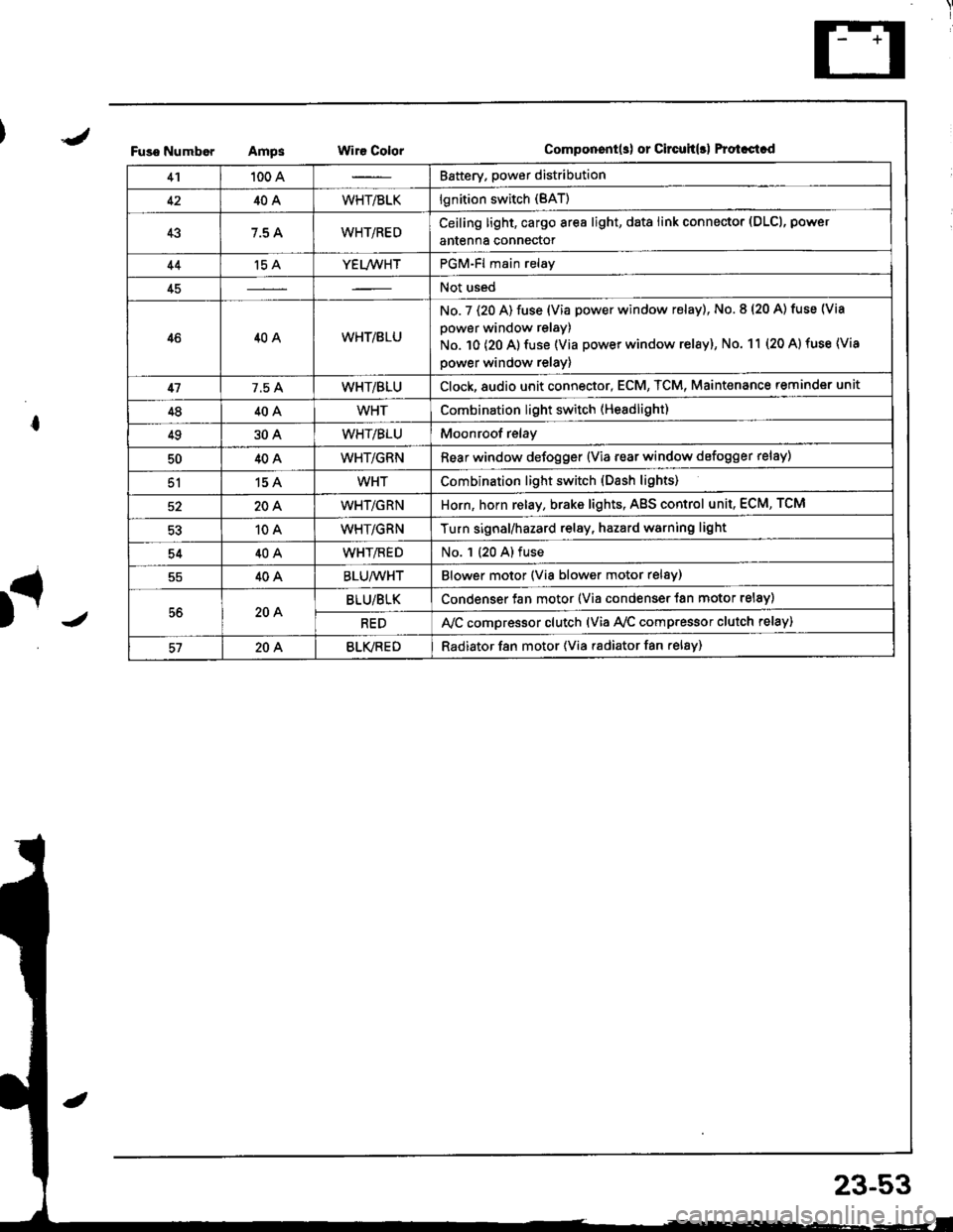
Fuso NumborAmpsWir€ ColorComponent(s) or Circuh(rl Protastcd
41100 ABattery. power distribution
4240AWHT/BLKlgnition switch (BAT)
437.5 AWHT/REDCeiling light, cargo area light, data link connector (DLCl, power
antenna connector
44't5 AYEL/WHTPGM-Fl main relay
45Not used
4640AWHT/8LU
No. 7 (20 A) fuse (Via power window relay), No. 8 (20 A) tuse (Via
power window relay)
No. 10 (20 A) fuse (Via power window relay), No. 11 (20 A) fuse (Via
power window relay)
417.5 AWHT/BLUClock,8udio unit connector, ECM, TCM, Maint€nance reminder unit
4840AWHTCombination light switch (Headlight)
4930AWHT/BLUMoonroof relay
5040AWHT/GRNRear window defogger {Via rear window defogger relay)
51154WHTCombination light switch (Dash lights)
20AWHT/GRNHorn, horn relay, brake lights, AgS control unit, ECM, TCM
10AWHT/GRNTurn signal/hazard relay, hazard warning light
5440AWHT/flEDNo. 1 (20 A) fuse
40ABLU/WHTBlower motor (Via blower motor relsy)
56204BLU/BLKCondenser fan motor (Via condenser {an motor relay)
REDA,/C compressor clutch (via Ay'c comp.essor clutch relay)
57204BLVREDRadiator f8n motor (Via radiator fan relay)
23-53
Page 1126 of 1681
1
I
PowerRelays
RelayTest
JNOTE: See page 23-194 for turn signal/hazard relay
input test.
Normally.open type:
fWC2i
1. Check for continuitv between the terminals.
. There should be continuity between the A and B
terminals when power and ground are connect-
ed to the C and D terminals.
. There should be no continuity between the A
and B terminals when power is disconnected.
<2
F;Z
,,A
/ l'El--E \
ey
Normally-opon type:
'1. Check continuity between relay terminals.
. There should be continuity between the A and C
terminals when power and ground are connect-
ed to the B and D terminals.
o There should be no continuitv when oower is
disconnacted,
o Power window relay
. Radiator fan relay
. Condenser fan relay
. AVC compressor clutch relay
Typel:
c
I Blower motor relay
. Rear window defogger relay
Typel:
Terminal
P";(c5t--__\B
Disconnected
Connectedoo
Terminal
P"*"r(B5-lc
Connectedoo
Disconnected
Page 1131 of 1681
Starting System
Component LocationIndex
STARTER CUT RELAY (M/T)
Test, page 23-70
A/T GEAR POSITION SWITCHTest, page 23-144CLUTCH INTERLOCK SWITCH IM/T}Test, page 23-79Switch ,Adiustment, section 12
Replacement,
BATTERYTest, page 23 76
STARTERlest, page 23-77Solenoid Test, page 23 79Replacement, page 23'80Overha!1, page 23'81Reassembly, page 23'86
23-74
Page 1132 of 1681
Circuit Diagram (M/Tl
tJ
STARTEBCUT RELAY
)/
ll-G2o1G401
rAa rtFz5- r3
) -rr
CLUTCHINTERLOCKSW]TCH
IGNITIONX SWITCH
!_*",.^-*-G-l
"T"
BTKWHT BLKWHT
llr - tr |
BLKFED 8LU/BLK
- BLK,BE' I__-lrror.oo*
I I
+Yffii'"'Tf'o' | |
u"T-l
i,t^il'r** | |
=-T--. I
twt t
l$*Tl r
IA II
BLK
tY--lt I-|ffim-
|
rl
UNDEB HOOD FUSE/BELAY BOX
No 41 (100A) N0.42 (404)
Page 1134 of 1681

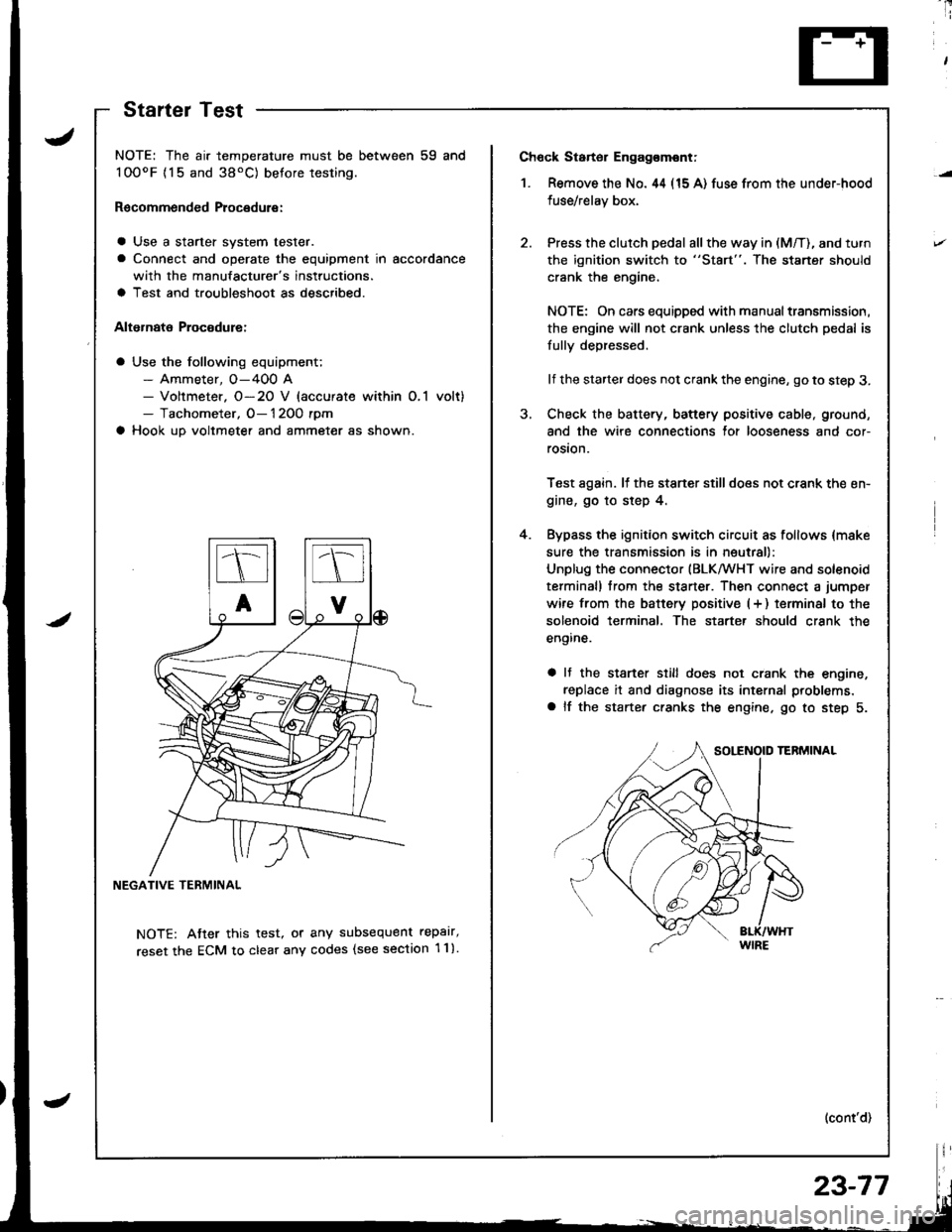
Ch6ck Starter Engag€mont;
1. Remove the No. 44 (15 A) fuse from the under-hood
fuse/relay box,
Press the clutch pedal all the way in (M/T), and turn
the ignition switch to "St8rt". The staner should
crank the engine,
NOTE: On cars equipped with manual transmission,
the engine will not crank unless the clutch pedal is
fully depressed.
lf the starter does not crank the engine, go to step 3.
Check the battery, battery positive cable, ground,
and the wire connections for looseness and cor-
rosion.
Test again. lf the stsner stilldoes not crank the en-
gine, go to step 4.
Bypass the ignition switch circuit as follows {make
sure the transmission is in neutral)
Unplug the connector (BLKMHT wire and solenoid
terminal) trom the staner. Then connect a jumper
wire from the batterv positive (+ ) terminal to the
solenoid terminal. The starter should crank the
engine.
a It the stsrter still does not crank the engine,
replace it and diagnose its internal problems,
a lf the starter cranks the engine. go to step 5.
(cont'd)
4.
NOTE: The air temperature must be between 59 and
100oF {15 and 38'C) betore testing.
Recommended Procedure:
a Use a starter system tester.
a Connect and operate the equipment in accordance
with the manufacturer's instructions.
a Test and troubleshoot as described.
Alternate Procodure:
a Use the following equipment;- Ammeter, O-400 A- Voltmeter. O-20 V (accurate within O,1 volt)- Tachometer, O- 1 2OO rpm
a Hook up voltmeter and ammeter as shown.
NEGATIVE TERMINAL
NOTE: Atter this test, or any subsequent repalr,
reset the ECM to clear any codes (see section 1 1).
StartelTest
23-77
Page 1135 of 1681

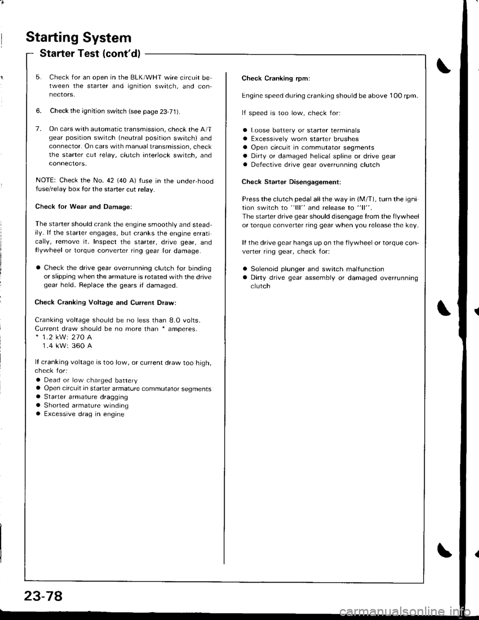
Starting System
Starter Test (cont'dl
Check Cranking rpmr
Engine speed during cranking should be above 1OO rpm.
lJ speed is too low, check for:
a Loose batlery or starter terminals
a Excessively worn starter brushes
a Open circuit in commutator segments
a Dirty or damaged helical spline or drive gear
a Defective drive gear overrunning clutch
Check Starter Disengagement:
Press the clutch pedal all the way in (M/T), turn rhe igni
tion switch to "lll" and release to "11".
The starter drive gear should disengage from the flywheel
or torque converter ring gear when you release the key.
It the drive gear hangs up on the flywheel or torque con-
verter ring gear, check for:
a Solenoid plunger and switch mallunction
a Dirty drive gear assembly or damaged overrunning
clutch
5. Check for an open in the BLK/WHT wire circuit be
tween the starter and ignition switch, and con-
necrors,
6. Check the ignition switch (see page 23-71).
7. On cars with automatic transmission, check the A/Tgear position switch (neutral position switch) and
connector. On cars with manualtransmission, check
the starter cut relay, clutch interlock switch, and
connectors.
NOTE: Check the No. 42 (40 A) fuse in the under,hoodfuse/relay box for the starter cut relay.
Check Jor Wear and Damage:
The starter should crank the engine smoothly and stead,ily. lf the starter engages, but cranks the engine errati
cally, remove it. Inspect the starter, drive gear, andllywheel or torque converter ring gear lor damage.
a Check the drive gear overrunning clutch for binding
or slipping when the armature is rotated with the drivegear held. Replace the gears i{ damaged.
Check CJanking Voltage and Current Draw:
Cranking voltage should be no less than 8.O volts.
Current draw should be no more than * amperes.* 1.2 kW: 27O A
1 .4 kW: 360 A
It cranking voltage is too low, or current draw too high,check for:
a Dead or low charged batterya Open circuit in starter armature commutator segmentsa Starter armalure dragging
a Shorted armature windinga Excessive drag in engine