Page 1457 of 1681
Cruise Control (cont'd)
- How the Circuit Works
The cruise control system uses mechanical and
electrical devices to maintain the car's soeed at a
setting selected by the driver.
System Description
The cruise control unit receives command signals
from the cruise control main switch and the cruise
control SevBesume switch. With the ignition switch
in ON (ll) or START (lll), voltage is provided to the
cruise control main switch. When you push the
switch to on, power is provided to the cruise control
unit and the brake switch.
The cruise control unit receives information about
operating conditions from the brake switch, the
ignition control module (lCM), the vehicle speed
sensor (VSS), and the clutch switch (manual
transmission) or the A,/T gear positton switch
(automatic transmission). The cruise control unit
then sends signals to the cruise conirol actuator
which regulates the throttle position to maintain the
selected speed. The control unit compares the
aclual speed of the car to the selected speed. The
control unit then uses the result of that comoarison
to oDen or close the throttle.
The brake switch releases the system's control of
the throttle at the instant you press on the brakepedal. The switch sends a signal to the control unit
by removing power from the normally closed brake
input (GRY wire), and providing power at the
normally open brake input (GRNMHT wire). The
control unit responds by allowing the throttle to
close. The clutch switch or the A/T gear position
switch sends a "disengage" signal to the control unit
that also allows the throttle to close.
The cruise control system will set and automatically
maintain any speed above 25 mph (40 km/h). To set
it, make sure the main switch is on and the switch
indicator is on. Then, after reaching the desired
speed, press the set switch. This sends a "set"
signal to the cruise control unit which, in turn,
controls the cruise control actuator to maintain the
set soeed.
When you push the SET switch and the cruise
control system is on, the "cruise control" ON
indicator lights up.
34-4
You can cancel the cruise control system by
turning the main switch off. This removes power to
the control unit and erases the set sDeed from
memory. lf the system is disengaged temporarily
by the brake switch, or clutch switch, and the car's
speed is still above 25 mph, press the RESUME
switch: the car will automatically return to the
previously set speed.
For gradual acceleration without pressing the
accelerator pedal, push the RESUME switch and
hold it there. This will send an "acceleration" signal
to the control unit. When you release the switch, the
system will be reprogrammed tor the new speed. To
slow the car down, push the SET switch in and hold
it there. This sends a "deceleration" signal to the
control unit, causing the car to coast. When the
desired speed is reached, release the SET switch.
This reprograms the system for the new speed.
Reter to the Service Manual (Section 23, Electrical)
for specific tests or troubleshooting procedures.
Page 1477 of 1681
A/C Gompressor Controls
FUS€ 55(GoNDEXSEA fAN)204
UNDER.HOOOFUSE/RELAYBOX
@r-T------.I UNDER-DASHI t FUSE 17 I FUSE/RELAY
| ) LBEL, t19T^..
I I r.uo ^ _ l--*I I lee Power I: {--t Diskibdion. :
L_I_fiT_.!I Y C439
".^,tr. |
"'oto u'
ll erx,.ver 36€ Powera ---i Distribution,page tO-0.
BLX/YEL I
" IFi:,u.^
See PowerDislribution,page 1G'l .
NCCOMPR€SSORCLUTCHREI.AYPtloro n-Y c905
-*----------f
"*l'--
,1,*,
"-l
"ft:,,
lll[ 133,]+'"1F**
;f
I. (on bracket)
- '98199 models with A/T - - - -
r -^ ^-^:'l TRANSMTSSTONCONTROL: rr!P!I.. : MoDULE| ^;;', | (rcM)L-Z-J iuoro sr24 Y C420
BLK/RED
POWERTRAINor ENGINECONTROLMODULE(PCM or ECM)PHOfO 77 (94 99)ly'C ON inDut{ACS}
L--,S"s-i(98- 99 s) Y (C4o8 '�98-'�99)
27 tl C409
",-r,"ao II aLuneo
ar< ree Fans
ilaurneo I
v
ToAonlacrng page.
62
Page 1479 of 1681
A/C Gompressor Controls (conrd)
- How the Circuit Works
Battery voltage is supplied through fuse 56 to the
A,/C compressor clutch relay contacts at all times.
With the ignition switch in ON (ll), voltage is applied
to the coil of the A,/C compressor clutch relay
through fuse 17. When you push the A,/C switch
ON, and the heater fan switch is in posation 1, 2, 3,
or 4, a "ground" input is provided to the engine or
powertrain control module (ECM or PCM) through
the A,/C thermostat and the A,/C pressure switch.
The A,/C compressor clutch relay is grounded by the
engine or powertrain control module (ECM or PCM).
When energized, the A,/C compressor clutch relay
allows battery voltage to turn on the A,/C
comDressor clutch,
The A,/C ON indicator light comes on when the A"/C
system is requested.
A,/C Thermostat
The A,/C thermostat is located on the evaoorator
housing. The AJC thermostat turns off the A,/C
compressor clutch if the temperature at the
evaporator goes below 3'C (37'F). This prevents
condensation from freezing on the evaporator fins
and blocking the air delivery into the passenger
compartment. The blower motor will keep running
when the sensor lurns off the compressor.
A,/C Pressure Switch
The A,/C pressure switch is located in the condenser
outlet line where refrigerant is in a high
temperature/high pressure liquid state. The switch
will sense abnormally high or low pressure, and
open the circuit. This removes ground, and the
compressor will stop running.
Refer to the Service Manual (Section 22,
Air Conditioning) for specific tests or
troubleshooting procedures.
62-2
Page 1483 of 1681
Fans (cont'd)
- How the Gircuit Works
When the ignition switch is in ON (ll), voltage is
applied to the coils of the radiator fan relay and the
condenser fan relay (with A,/C) through fuse 17.
Whenever a ground is provided to the radiator fan
relay and condenser fan relay, the relays are
energized, turning on the radiator fan motor and
condenser fan motor. The relays can be grounded
by the radiator fan switch, engine or powertrain
control module (ECM or PCM) (USA), or the A,/C
and heater lan switches via the A'lC pressure switch
and the A,/C lhermostat.
A,/C Thermostat
The A,/C thermostat is located on the evaporator
housing. The A/C thermostat turns oft the A/C
compressor clutch it the temperature at the
evaporator goes below 3'C (37"F). This prevents
condensalion from freezing on the evaporator fins
and blocking the air delivery into the passenger
compartment. lt the temperature goes below 3'C
(37'F) turning off the A"/C thermostat, and the
BLU/RED wire at the A,/C diode was the only wire
providing ground to the condenser and radiator
fan relays (A,/C switch on, heater fans switch on,
radiator fan switch open, and ECM or PCM fan
controi output not grounded), the relay will
deenergize removing voltage from the condenser
and radiator fan motors causing them to stop
running.
A,/C Pressure Switch
The AJC oressure switch is located in the condenser
outlet line where refrigerant is in a high
temperature/high pressure liquid state. The A,/C
switch turns off the A,/C compressor clutch if it
senses abnormally high or low pressure. lf the A'lC
pressure switch opens, and the BLU/RED wire at
the A/C diode was the only wire providing ground
to the condenser and radiator fan relays (L/C switch
on, heater fans switch on, radiator lan switch open'
and ECM or PCM fan control output not grounded),
the relay will deenergize removing voltage from the
condenser and radiator fan motors causing them to
stop running.
A./C Diode
This diode orevents the radiator fan switch f rom
grounding the "A'lC ON" input to the engine or
powertrain control module (ECM or PCM).
Refer to the Service Manual (Section 23, Electrical)
for specific tests or troubleshooting procedures.
63-3
Page 1487 of 1681
NOTE: Fuse 31 is HOT with lgnition Switch in START (lll) and clutch pedal depressed or A./T Gear Selector
in PARK (P) or NEUTRAL (N), see Starting System, pages 21 and 21-1.
See BrakeSystemlndicatorI i^ht
c504PHO|O 62
SBe Headlight
FUSE 31STAATEAS|GTAL7.54uee
Switch,page 100-'1. I
FUSE 30usrnu EtlTUGT'Tl|?.5A
S€e BrakoSystemlndicatorUqht
INTEGBATEDCONTROL UNITPHOfO 62
UNDER-OASHFUSE/RELAYBOX
SeeCeilingLight
c422
DRIVER'S DOORswtTcHClosed withdoor open.
PHoto 88 (sedan)
70-1
Page 1488 of 1681
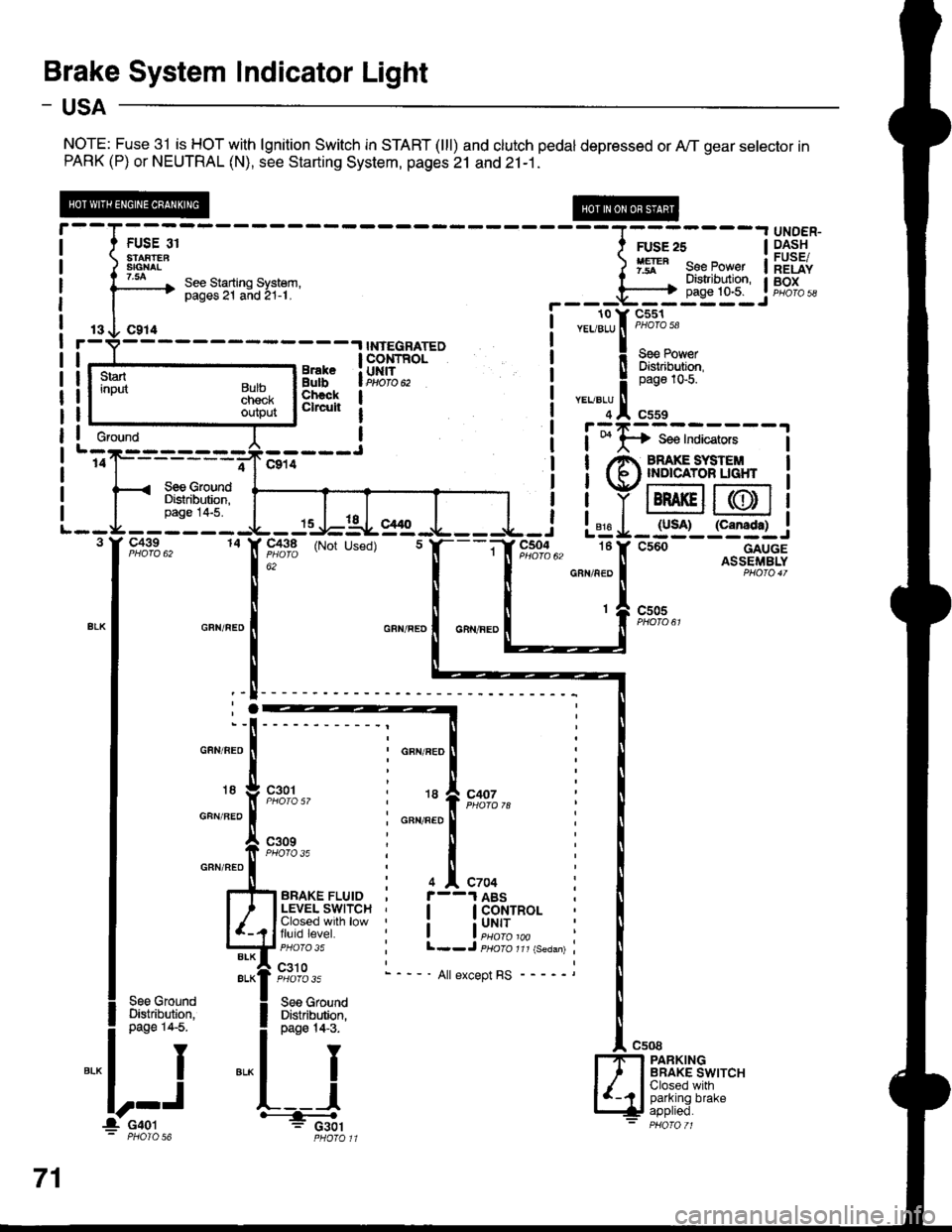
Brake System Indicator Light
- USA
NOTE: Fuse 31 is HOT with lgnition Switch in START (lll) and clutch pedal depressed or A,/T gear selector inPARK (P) or NEUTRAL (N), see Starting System, pages 21 and 21-1.
13 O C914r-V----- -.l INTEGRATED
!r--_.ts__rr,"*" !ERT'"o. | lBtr,i{,fr;
Lj':e--:---J I i;I;:;*;;.;
'of------;-Jclil ! !/e ffiS,'#LT",l< see crouno I I Vr:-:--t r--:=:
ilrF'fi$l ffiiiY@@
-3:".J:iTIS:
I T..T I
Il
! ! YIBRAKEII(DI1
- - - - - - -{L - Js-J=-AL- g1g -.1- - - -{- - i L"jg I _ lyso)_ l"g:f.l_..1
F,o:fo", to IF,flt'3 (Not used) t f,---if r",*%u, tef csoo---.--^g+.rSS
r--T- --- ----r UNDER-
I t FUSE or I ruse zs | 9.4.s!t
i ) 3ffi8" ) 1ry" eeeJo"", ilEiiv
i l3--* ::3"Tii'lH.'ti:i' r il"'li$lr if,g[;,
I | !---r-o v-cl6r-
----.,NrEGRArED i
""lltrt:1'
3ni"iFfi,t-- i !Flif{#r
3i}fi[ | i
"':lln*
, I r:zr=---
*"*'l
.:.:,*,
L--g--3 I' C439
15 -l-lal- el/ t
14 X 91^3,q (Not Used)
; : 816 | IUJA' {LaI|Agtt .J L=g-:__i_-:J
"; " I ll -"," - ll AsslFrr,rBLYGRN/NED I PHO|O4T
c505
GFN/BEO
18
GFN/BEO
GRN/NEO
GFN/FED
18
GFN/FED
I
I
'-l
;.
t
;"x
c301
c309PHOfO 35
c407
4 ^ C704
I GoNTROL
i uNrr
l--J psoro rrr {seaan)
- ' All except RS
See GroundDi$tribution,page 14-5.
PARKINGBRAKE SWITCHClosed withparking brake
Gfound
71
l_ c4ol' PHOIO 56
Page 1489 of 1681
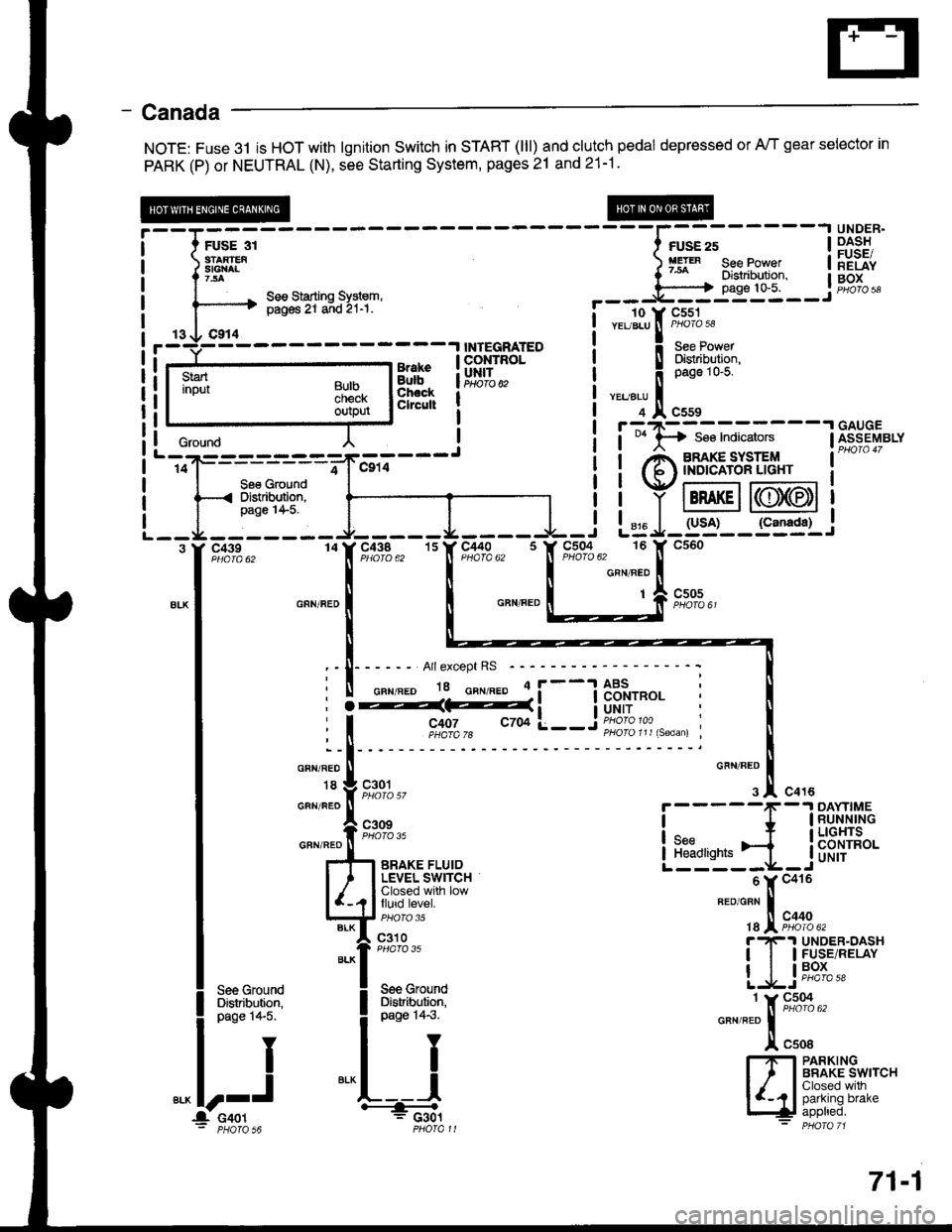
- Canada
NOTE: Fuse 3l is HOT with lgnition Switch in START (lll) and clutch pedal depressed or A/T gear selector in
PARK (P) or NEUTRAL (N), see Starting System, pages 21 and 21-1.
;;;----
----l;";;-----l
iiSF:'
:'eI[^ ) fg'" see Power | lEiiv
^ seesiarrins sysrem, --- j'[ffi-- j #"1""------'+ pig6 Zr a;d 2r-r. !- - To-v cssr
i r- 3li:Tf8l r---r--_l
| | y tBRAKEil((lJ)(EDt I
L - -r4 - - - - - - - r- - - - - J. - - - - -l - i L= J- g'j'- - S3g1-,
.[Hr*. "IF#1s,, ''f,"c,flls. 'It*'t"i_[
^.^.
*- I o^n".' | | o"n".o L___:;[ s;*,,
lri:
tl
I :-I------ Arrexcept Rs -----------: t
I ii%d#i__jflffi: i I
| """;l
'- ll
I * Vg,l.gl,,
o'""'1.!.
"o'u
i-----f
-1Ri-[iil,'"
I
*"ff;i;-.,.,,"
LEb'r.ji_jb'f,{H*
I l#[i.#rsr
"-"fX;;;;.,
| ].1s*" [Tr P.ls.',ePfiv
|
**1
Lljti';-! see Ground ! See Grouno
'-,oij---------=-*"-,,;---J
i i Anmg"#l''3;' i-
-
l--ffi'Pilr"r-l t ' iiYffi@i
--I -i:"-:-- J-----L---I -i L= J-rs'i-- r"=sr.i
i it"!,8li6l i iq,iit"l :'fl"";'#.,
i
**'?
i
**''; *""*i:;;-
l!."1 IrflBAt['JS*,""
l--J
*^L---l
|y', I Shtrl'l-"
itooo, '---& [+! iPPtreo.: PHoTa s6 PHofall - PHora 71
: | - - --'l uauuc
crourd l ! i t *lA se€ Indicators lfr1s-eyerv
BulbcnecKoutpur
71-1
Page 1588 of 1681
127, Cenler Front of Roof (Sedan)130. Behind Left Side of Dash, on Clutch Pedal Support
128. Below Left Side of Front Console131 . Right Side of Front Console
129. Behind Left Side ot Dash, on Brake Pedal Support132. Below Center of Intake Manifold
l)
201-21