1998 HONDA INTEGRA clutch
[x] Cancel search: clutchPage 1596 of 1681
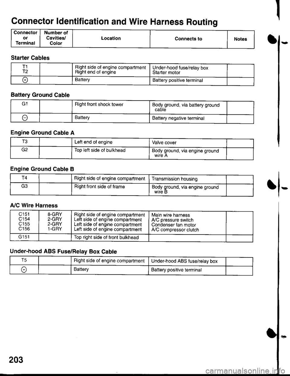
Connector ldentification and Wire Harness Routing
Connector
OT
Terminal
Number of
Cavities/
Color
LocationConnecls toNotesI
fl-
Starter Cables
T1
T2Right side of engine compartmentRight end of engineUnder-hood fuse/relav boxStarter motor
oBatteryBattery positive terminal
Battery Ground Cable
lRight front shock towerBodyground, via battery ground
ABatteryBattery negative terminal
Engine Ground Cable A
T3Left end of engineValve cover
Top left side ol bulkheadBody ground, via engine ground
Engine Ground Cable B
T4Right side of engine compartmentTransmission housing
Right front side of trameBody ground, via engine ground
wrre b
A,/C Wire Harness
Under-hood ABS Fuse/Relay Box Cable
203
c151
c'154utSc
u tco
8-GRY
2-GRY
2-GRY
1-GRY
Right side ol engine compartmentLeft side of engine compartmentLeft srde of engine compartmentLeft side of engine compartment
Main wire harness
A'lC pressure switch
Condenser tan motorA,/C compressor clutch
lrlclTop right side ot front bulkhead
T5Right side of engine compartmentUnderhood ABS fuse/relav box
\,BatteryBattery positive terminal
Page 1608 of 1681
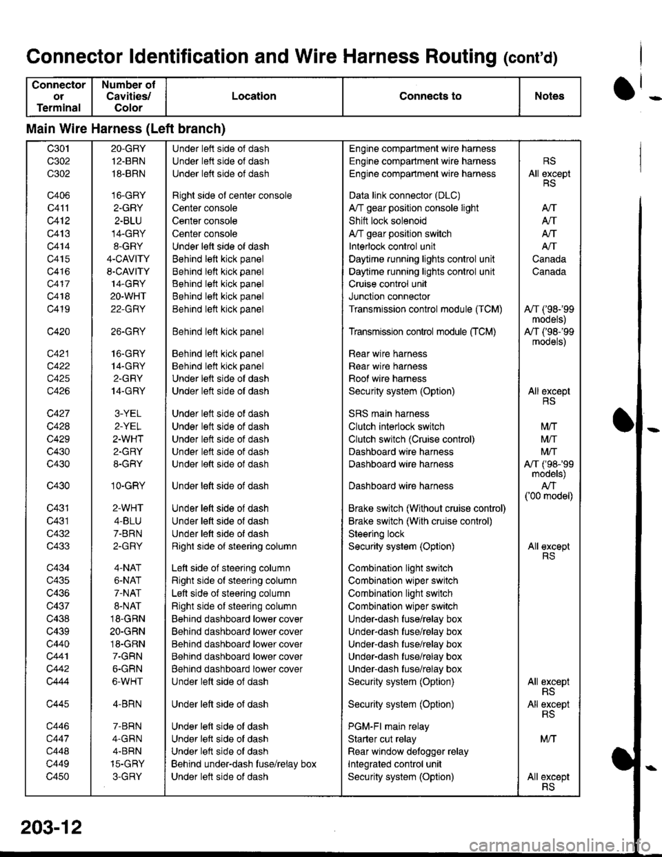
Connector ldentification and Wire Harness Routing (conrd)
Connector
ot
Terminal
Number of
Cavities/
Color
LocationConnects toNotes
Main Wire Harness (Left branch)
c30t
c302
c302
c406
c41'l
c412
c413
c414
c415
c416
c417
c418
c419
c420
c422
c425
c426
c427
c428
c429
c430
c430
c430
c431
c431
c432
c433
c434
c435
c436
c437
c438
c439
c440
c441
c442
Q444
c445
c446
c447
c448
c449
c450
2O-GBY
12.BRN
18-BRN
16-GRY
2-GRY
2-BLU
14-GRY
8-GRY
4-CAVITY
S.CAVITY
14.GRY
2O-WHT
22-GRY
26.GRY
16.GRY
14-GRY
2.GRY
14.GRY
3-YEL
2-YEL
2-WHT
2.GRY
8-GRY
1O-GRY
2-WHT
4-BLU
7-BRN
2-GRY
4-NAT
6-NAT
7-NAT
8-NAT
18-GRN
2O-GRN
18-GRN
7-GRN
6-GRN
6-WHT
4-BRN
7-BRN
4.GRN
4.BBN
15-GHY
3-GRY
Under left side of dash
Under lett side ol dash
Under left side of dash
Right side ol center console
Center console
Center console
Center console
Under left side of dash
Behind left kick panel
Behind lett kick panel
Behind left kick panel
Behind left kick panel
Behind lett kick panel
Behind lett kick panel
Behind left kick panel
Behind lelt kick panel
Under left side of dash
Under left side ot dash
Under lett side of dash
Under lett side of dash
Under left side of dash
Under left side of dash
Under left side of dash
Under lett side of dash
Under left side of dash
Under left side of dash
Under lett side of dash
Right side of steering column
Lett side of steering column
Right side of steering column
Left side of steering column
Right side of steering column
Behind dashboard lower cover
Behind dashboard lower cover
Behind dashboard lower cover
Behind dashboard lower cover
Behind dashboard lower cover
Under left side of dash
Under left side of dash
Under left side of dash
Under left side of dash
Under left side of dash
Behind under-dash fuse/relay box
Under lett side of dash
Engine compartment wire harness
Engine compartment wire harness
Engine comparlmenl wire harness
Data link connector (DLC)
A/T gear position console light
Shitt lock solenoid
A/T gear position switch
Interlock control unit
Daytime running lights control unit
Daytime runnang lights control unit
Cruise control unit
Junction connector
Transmission control module (TCM)
Transmission control module CrCM)
Rear wire harness
Rear wir€ harn€ss
Roof wire harness
Security system (Option)
SRS main harness
Clutch interlock switch
Clutch switch (Cruise control)
Dashboard wire harness
Dashboard wire harness
Dashboard wire harness
Brake switch (Without cruise control)
Brake switch (With cruise control)
Steering lock
Security system (Option)
Combination light switch
Combination wiper switch
Combination light switch
Combinalion wiper switch
Under-dash fuse/relay box
Under-dash fuse/rglay box
Under-dash fuse/relay box
Under-dash fuse/relay box
Under-dash fuse/relay box
Security system (Option)
Security system (Option)
PGM-Fl main relay
Starter cut relay
Rear window detogger relay
Integrated control unit
Security system (Option)
RS
All exceptRS
AtT
Atf
AN
A/T
Canada
Canada
A,/T ('98-'99
models)
A,/T (,98-'99
models)
All exceptRS
M/T
Mtf
Mrf
A,/T ('98-'99models)
AN('00 model)
All exceptRS
All exceptRS
All exceptRS
MN
AII excsptRS
203-1
Page 1641 of 1681
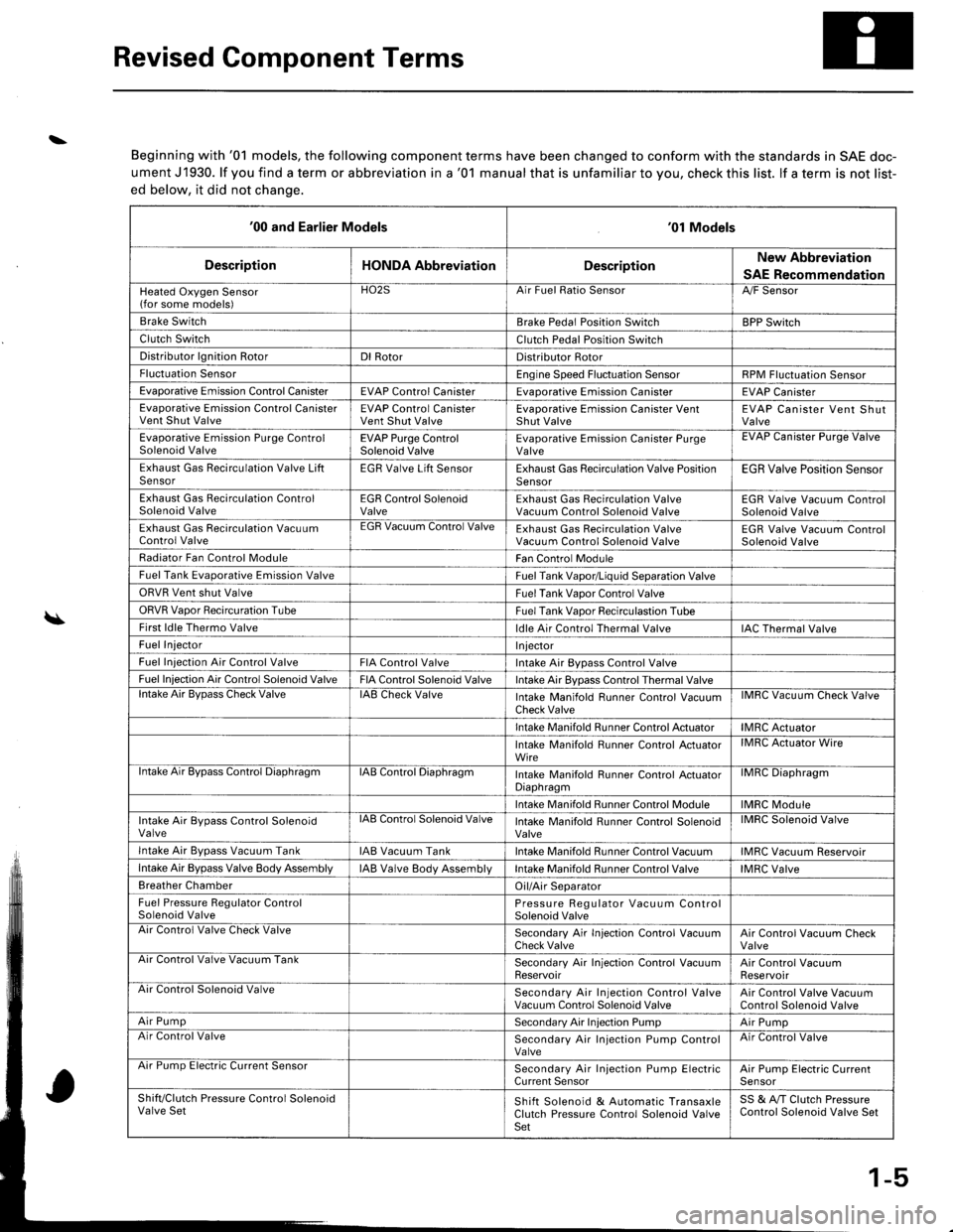
Revised Component Terms
\
\
Beginning with '01 models, the following component terms have been changed to conform with the standards in SAE doc-
ument J1930. lf you find a term or abbreviation in a '01 manual that is unfamiliar to you, check this list. lf a term is not list-
ed below, it did not chanqe.
'00 and Earlier Models'01 Models
DescriptionHONDA AbbreviationDescriptionNew Abbreviation
SAE Recommendation
Heated Oxygen Sensor(for some models)HO2SArr ruet llalto )ensorA,/F Sensor
Brake SwitchBrake Pedal Position SwitchBPP Switch
Clutch SwitchClutch Pedal Position Switch
Distributor lgnition RotorDl RotorDistributor Rotor
Fluctuation SensorEngine Speed Fluctuation SensorRPM Fluctuation Sensor
Evaporative Emission Control CanisterEVAP Control CanisterEvaDorative Emission CanisterEVAP Canister
Evaporative Emission Control CanisterVent Shut ValveEVAP Control CanisterVent Shut ValveEvaporative Emission Canister VentShut ValveEVAP Canister Vent ShutValve
Evaporative Emission Purge ControlSolenoid ValveEVAP Purge ControlSolenoid ValveEvaporative Emission Canister PurgeValveEVAP Uanister Purge Valve
Exhaust Gas Recirculation Valve LiftSensorEGR Valve Lift SensorExhaust Gas Recirculation Valve PositionSensorEGR Valve Position Sensor
Exhaust Gas Recirculation ControlSolenoid ValveEGR Control SolenoidValveExhaust Gas Recirculation ValveVacuum Control Solenoid ValveEGR Valve Vacuum ControlSolenoid Valve
Exhaust Gas Recirculation VacuumControl ValveEGR Vacuum Control ValveExhaust Gas Recirculation ValveVacuum Control Solenoid ValveEGR Valve Vacuum ControlSolenoid Valve
Radiator Fan Control ModuleFan Control Module
Fuel Tank Evaporative Emission ValveFuel Tank Vapor/Liquid Separation Valve
ORVR Vent shut ValveFuel Tank Vaoor Control Valve
ORVR Vaoor Recircuration TubeFuel Tank Vaoor Recirculastion Tube
First ldle Thermo Valveldle Air Control Thermal ValveIAC Thermal Valve
Fuel InjectorI njector
Fuel Iniection Air Control ValveFIA Control ValveIntake Air Bypass Control Valve
Fuel Injection Air Control Solenoid ValveFIA Control Solenoid ValveIntake Air Bypass Control Thermal Valvelntake Air BvDass Check ValveIAB Check ValveIntake Manifold Runner Control VacuumCheck ValveIMRC Vacuum Check Valve
Intake Manifold Runner Control ActuatorIMRC Actuator
Intake Manifold Runner Control ActuatorWireIMRC Actuator Wire
ntake Air Bypass Control DiaphragmIAB Control DiaphragmIntake Manifold Runner control ActuatorDiaphragmilvrr1u urapnragm
Intake Manifold Runner Control ModuleIMRC Module
Intake Air Bypass Control SolenoidValvelAts Control Solenoid ValveIntake Manifold Runner Control SolenoidValveIMRC Solenoid Valve
Intake Air Bvpass Vacuum TankIAB Vacuum TankIntake Manifold Runner Control VacuumIMRC Vacuum Reservoir
Intake Air Bypass Valve Body AssemblyIAB Valve Body AssemblVIntake Manifold Runner Control ValveIMRC Valve
Breather ChamberOil/Air Separator
Fuel Pressure Regulator ControlSolenoid ValvePressure Regulator Vacuum ControlSolenoid ValveAir Control Valve Check ValveSecondary Air In.jection Control VacuumCheck ValveAir Control Vacuum CheckValveArr Control Valve Vacuum TankSecondary Air Injection Control VacuumReservoirAir Control VacuumReservoirAir Control Solenoid ValveSecondary Air Injection Control ValveVacuum Control Solenoid ValveAir Control Valve VacuumControl Solenoid Valve
Air PumpSecondary Air Injection PumpAir PumpAir Control ValveSecondary Air Injection Pump ControlValveAir Control Valve
Arr rump tsreclnc uurrent bensorSecondary Air Injection Pump ElectricCurrent SensorAir Pump Electric CurrenlSensor
Shift/Clutch Pressure Control SolenoidValve SetShift Solenoid & Automatic TransaxleClutch Pressure Control Solenoid ValveSet
SS & A,/T Clutch PressureControl Solenoid Valve Set
1-5
Page 1642 of 1681
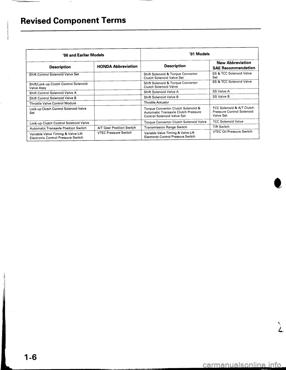
Revised Component Terms
'00 and Earlier Models'01 Models
DescriptionHONDA AbbreviationDescriptionNew Abbreviation
SAE Recommendation
Shift Control Solenoid Valve SetShift Solenoid & Torque ConvertorClutch Solenoid Valve SetSS & TCC Solenoid ValveSet
Shift/Lock-up Clutch Control SolenoidValve Assy
Shift Solenoid & Torque ConvertorClutch Solenoid Valve
SS & TCC Solenoid Valve
Shift Control Solenoid Valve AShift Solenoid Valve ASS Valve A
Shift Control Solenoid Valve BShift Solenoid Valve BSS Valve B
Throttle Valve Control ModuleThroftle Actuator
Lock-uo Clutch Control Solenoid ValveSetToroue Convertor Clutch Solenoid &Automatic Transaxle Cl utch PressureControl Solenoid Valve Set
TCC Solenoid & Av/T ClutchPressure Control SolenoidValve Set
Lock-uo Clutch Control Solenoid ValveTorque Convertor Clutch Solenoid ValveTCC Solenoid Valve
Automatic Transaxle Position SwitchA,/T Gear Position SwitchTransmission Range SwitchT/R Switch
Variable Valve Timing & Valve LiftElectronic Control Pressure Switch
VTEC Pressure SwitchVariable Valve Timing & Valve LiftElectronic Control Pressu re Switch
VTEC Oil Pressure Switch
Page 1648 of 1681
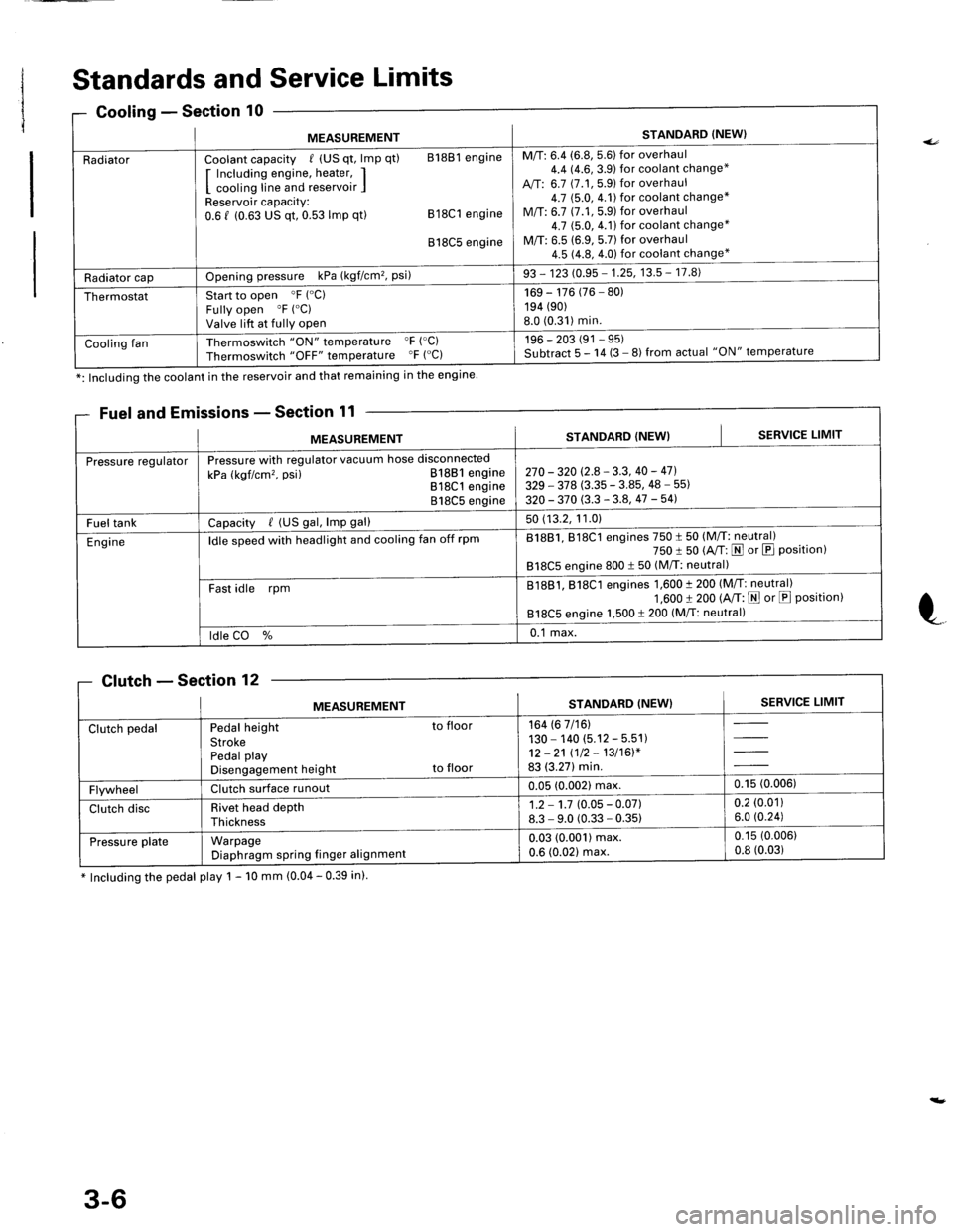
Standards and Service Limits
missions - Section 11
* Including the pedal play 1 - 10 mm (0.04 - 0.39 in).
0Gooling - Sectlon
MEASUREMENTSTANDARD (NEW}
RadiatorCoolant capacity / (US qt, lmp qt) 81881 engine
I Including engine, heater, II cooling line and reservoir IReservoir capacity:0.6 f (0.63 US qt, 0.53 lmp qt) 818C1 engine
818C5 engine
M/T: 6.4 (6.8, 5.6) for overhaul4.4 14.6,3.9) for coolant change*
A,/T: 6.7 (7.1, 5.9) for overhaul4.7 $.0,4.1)for coolant change*
M/T: 6.7 (7.1,5.9) for overhaul4.7 (5.0, 4.1) for coolant change*
M/T: 6.5 (6.9, 5.7) for overhaul4.5 (4.8, 4.0) for coolant change*
Radiator capOpening pressure kPa (kgf/cm'�, Psi)93 - 123 (0.95 - 1.25, 13.5 - 17.8)
ThermostatStart to open 'F ("C)
Fully open "F ("C)
Valve lift at fully open
169 - 176 (76 - 80)194 (90)
8.0 (0.31)min.
Cooling fanThermoswitch "ON" temperature "F ('C)
Thermoswitch "OFF" temperature "F ("C)196 - 203 (91 - 95)Subtract 5 - 14 (3 - 8) from actual "ON" temperature
*: Including the coolant in the reservoir and that remaining in the engine
Fuel and E
MEASUREMENTSTANDARD (NEW}SERVICE LIMIT
Pressure regulatorPressure with regulator vacuum hose disconnected
kPa (kgf/cm'�, psi) 81881 engine818C1 engine818C5 engine
270 - 320 (2.8 - 3.3, 40 - 47].
329 - 378 (3.35 - 3.85, 48 - 55)
320 - 370 (3.3 - 3.8, 47 -541
Fuel tankCapacity / (US gal, lmp gal)50 (13.2, 11.0)
Engineldle speed with headlight and cooling fan off rpm81881, 818C1 engines 750 t 50 (M/T: neutral)750 I 50 (A/T: N or E Position)818C5 engine 800 t 50 (M/T: neutral)
Fast idle rpmB1881, 818C1 engines 1,600 t 200 (M/T: neutral)1,600 t 200 (A/T: E or E Position)818C5 engine 1,500 t 200 (M/T: neutral)
ldle CO %0.1 max.
Clutch - Section 'lZ
MEASUREMENTSTANDARD (NEW}SERVICE LIMIT
Clutch pedalPedal height to floor
StrokePedal playDisengagement height to floor
164 (6 7/16)130 - 140 (5.12 - 5.51)12 -21 (12 - 13/16)*83 (3.27) min.
FlywheelClutch surface runoul0.05 (0.002) max,0.15 (0.006)
Clutch discRivet head depthThickness
1.2 - 1.7 (0.05 - 0.07)8.3 - 9.0 (0.33 - 0.35)0.2 (0.01)
6.0 (0.24)
Pressu re plateWarpageDiaphragm spring finger alignmenl
0.03 (0.001) max.0.6 (0.021 max.
0.15 (0.006)
0.8 (0.03)
3-6
Page 1649 of 1681
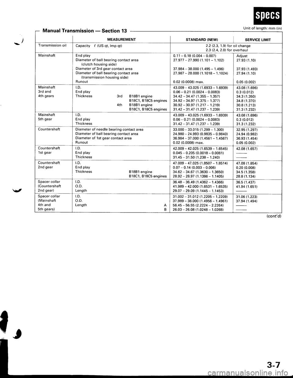
Unit of length: mm (in)Manual TransmissionSection 13
_/
/
MEASUREMENTSTANDARD (NEW}SEBVICE LIMIT
Transmission oilCapacity / (US qt, lmp qt)2.2 12.3, 1.9) for oil change2.3 12.4,2.0) for overhaul
MainshaftEnd playDiameter of ball bearing contact area(clutch housing side)Diameter of 3rd gear contact areaDiameter of ball bearing contact area(transmission housing side)Runout
0.1 1 - 0.18 (0.004 - 0.007)27 .977 - 27.990 (1 .101 - 1.102]|
37.984 - 38.000 (1.495 - 1.496)27.987 - 28.000 (1.1018 - 1.1024l.
0.02 (0.0008) max.
Adiust27 .93 (1.101
37.93 (1 .493)27 .94 11.101
0.05 (0.002)
Mainshaft3rd and4th gears
LD.End playThickness 3rd 81881 engine818C1, B18C5 engines4th 81881 engine818C1, 818C5 engines
43.009 - 43.025 (1 .6933 - 1 .(0.06 - 0.21 (0.0024 - 0.0083)34.42 - 34.47 (1 .355 - 1.357)34.92 - 34.97 (1.37 5 -'�t.377 )30.92 - 30.97 (1.2't7 -'�t.219)
31.42 - 31.47 n.237 - 1.239)
i939)43.0t0.3 ((
34.334.830.831 .3
(1.696)
.01211.350)1.370)1.21311.2321
Mainshaftsth geart.D.End playTh ickness
43.009 - 43.025 (1.6933 - 1.6939)0.06 - 0.21 (0.0024 - 0.0083)31 .42 - 31 .47 11 .237 - 1.2391
43.08 (1.696)
0.3 (0.012)
31.3 11.2321
CountershaftDiameter of needle bearing contact areaDiameter of ball bearing contact areaDiameter of 1st gear contact areaRunout
33.000 - 33.015 (1 .299 - 1 .300)24.980 - 24.993 (0.9835 - 0.9840)36.984 - 37.000 (1.4561 - 1.456710.02 (0.0008) max.
32.95 (1.2971
24.94 (0.982)
36.93 (1 .454)0.05 (0.002)
Countershaft1 st geart.D.End playTh ickness
42.009 - 42.025 (1.6539 - 1.6545)0.045 - 0.205 (0.0018 - 0.0081)31.45 - 31 .50 (1.238 - 1.240)
42.08 (1.657)
Countershaft2nd geart.D.End playThickness 81881 engine818C1, 818C5 engines
47.009 - 47 .025 (1.8507 - 1.8514)0.07 - 0.14 (0.003 - 0.006)34.62 - 34.67 (1 .3630 - 1.3650)28.92 - 28.97 (1.1386 - 1.1405)
47.08 (1 .8s410.20 (0.008)
34.5 (1.358)
28.8 (1.1341
Spacer collar(Countershafl
2nd gear)
t.D.o.D.Length
36.48 - 36.49 (1.4362 - 1.4366)41.989 - 42.000 (1.6531 - 1.6535)29.07 -29.09 (1.1445- 1.14531
36.5 (1 .437)41.94 (1.651)
Spacer collar(Mainshaft
4th and5th gears)
t.D.o.D.Length AB
31 .002 - 31 .012 11 .2205 - 't .2209'37.989 - 38.000 ( 1.4956 - 1.4961 )56.45 - 56.55 (2.2224 - 2.2264'�)26.03 - 26.08 (1.0248 - 1.0268)
31.06 (1 .223)37.94 (1 .494)
(cont'd)
Page 1651 of 1681
I
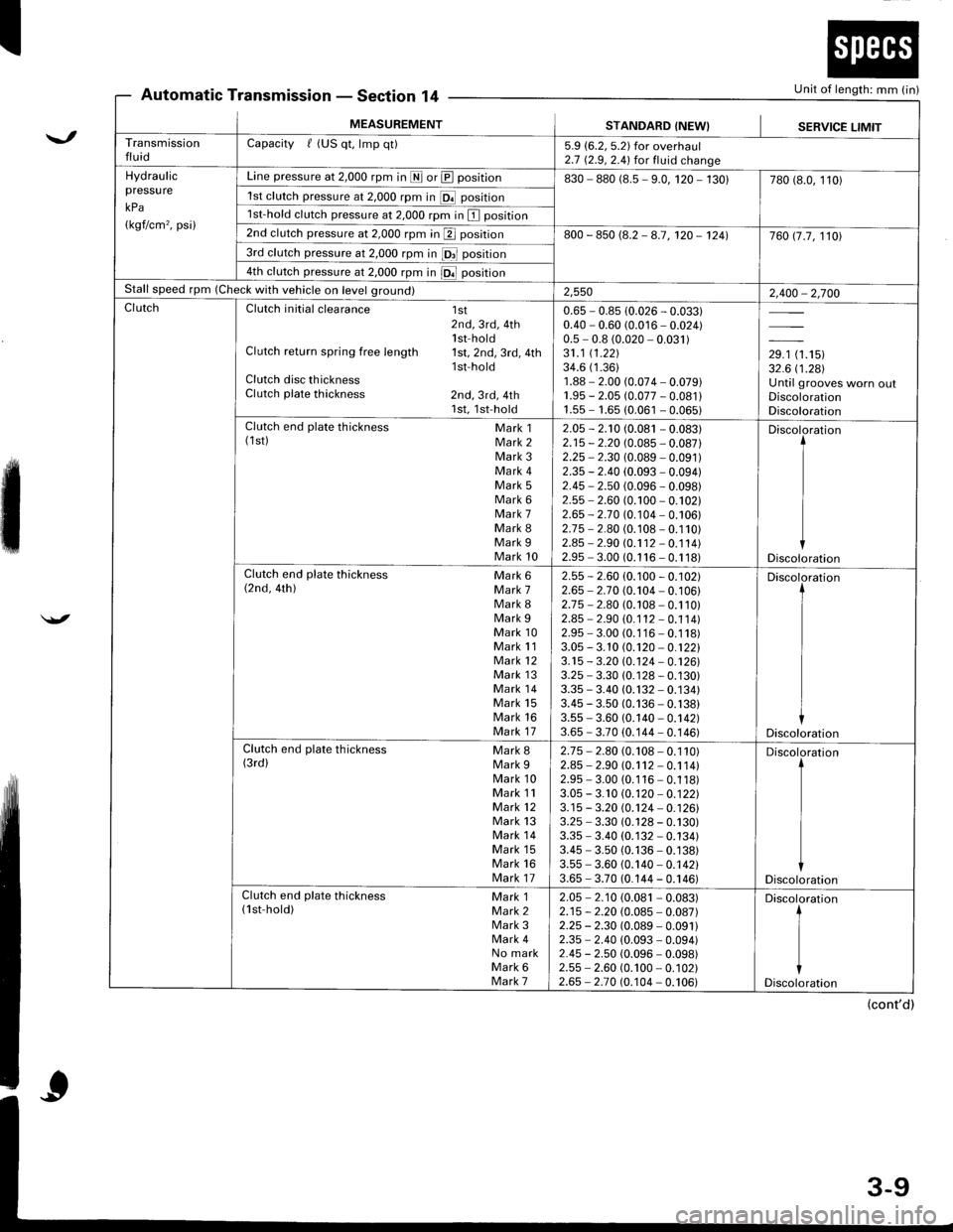
Automatic TransmissionSection 14
\.,
'
Unit of length: mm (in)- r;rEGl,l(tll I +
MEASUREMENTSTANDARD {NEW}SERVICE LIMITTransmissionfluidCapacity f (US qt, lmp qt)5.9 (6.2, 5.2) for overhaul2.7 (2.9,2.4) for fluid changeHydraulicpressu re
kPa
(kgf/cm'�, psi)
Line pressure at 2,000 rpm in I or @ position830 - 880 (8.5 - 9.0, 120 - 130)780 (8.0, 110)
1st clutch pressure at 2,000 rpm in [Of position
1st-hold clutch pressure at 2,000 rpm in I position
2nd clutch pressure at 2,000 rpm in p position800 - 850 (8.2 - 8.7, 120 - 1241760 17.7, 1101
3rd clutch pressure at 2,000 rpm in fOrl position
4th clutch pressure at 2,000 rpm in iOl position
Stall speed rpm (Check with vehicle on level ground)2,5502,400 - 2,700ClutchClutch initial clearance 1st2nd, 3rd, 4th1 st-hol dClutch return spring free length 1st,2nd,3rd,4thlsf holdClutch disc thicknessClutch plate thickness 2nd, 3rd, 4th1st,1st-hold
0.65 - 0.85 (0.026 - 0.033)0.40 - 0.60 (0.016 - 0.024)0.5 - 0.8 (0.020 - 0.031)31.1 (1.221
34.6 (1.36)
1.88 - 2.00 (0.074 - 0.079)1.95 - 2.05 (0.077 - 0.081 l1.55 - 1.65 (0.061 - 0.065)
,r, tr.'tur32.6 i'1.281Until grooves worn oulDiscolorationDiscolorationClutch end plate thickness Mark 1(1st) Mark 2Mark 3Mark 4Mark 5Mark 6Mark 7Mark 8Mark 9Mark 10
2.05 - 2.'t0 (0.081 - 0.083)2.15 - 2.20 (0.085 - 0.087)2.25 - 2.30 (0.089 - 0.091)2.35 - 2.40 (0.093 - 0.094)2.45 - 2.50 (0.096 - 0.098)2.55 - 2.60 (0.100 - 0.102)2.65 - 2-70 (0.104 - 0.106)2.75 - 2.80 (0.108 - 0.110)2.45 - 2.90 (0.1 12 - 0.1 14)2.95 - 3.00 (0.1 16 - 0.1 18)
Discoloration
Discoloration
Clutch end plate thickness Mark 6(2nd, 4th) Mark 7Mark 8Mark 9Mark 10Mark 11Mark 12Mark 13Mark 14Mark 15Mark 16Mark 17
2.55 -2.60 (0.100 - 0.102)2.65 - 2.7 0 (0.104 - 0. 1 06)2.75 - 2.80 (0.108 - 0.110)2.85 - 2.90 (0. 1 12 - 0.1 1 4)2.95 - 3.00 (0.1 16 - 0.1 18)3.05 - 3. 10 (0.120 - 0.12213.15 - 3.20 10.124 - 0.12613.25 - 3.30 (0. 1 28 - 0.130)3.35 * 3.40 (0.132 - 0.134)3.45 - 3.50 (0.136 - 0.138)3.55 - 3.60 (0.140 - 0.142)3.65 - 3.70 (0.144 - 0.146)
Discoloration
Discoloration
Clutch end plate thickness Mark g(3rd) Mark 9Mark 10Mark 11Mark 12Mark 13Mark 14Mark 15Mark 16Mark 17
2.75 - 2.80 (0.108 - 0.110)2.85 - 2.90 (0.1 12 - 0.1 14)2.95 - 3.00 (0.116 - 0.118)3.05 - 3.10 (0.120 - 0.12213.15 - 3.20 @j24 - 0.12613.25 - 3.30 (0.128 - 0.130)3.35 - 3.40 (0. 132 - 0.134)3.45 - 3.50 (0.136 - 0.138)3.55 - 3.60 (0.140 - 0.142)3.65 - 3.70 (0.144 - 0.146)
Discoloration
Discoloration
Clutch end plate thickness Mark 1(lst-hold) Mark 2Mark 3Mark 4No markMark 6Mark 7
2.05 - 2.10 (0.081 - 0.083)2.15 - 2.20 (0.085 - 0.087)2.25 - 2.30 (0.089 - 0.09112.35 - 2.40 (0.093 - 0.094)2.45 - 2.50 (0.096 - 0.098)2.55 - 2.60 (0.100 - 0. 1 02)2.65 - 2.70 (0.104 - 0.106)
Discoloration
t
I
iDiscoloration
(cont'd)
Page 1653 of 1681
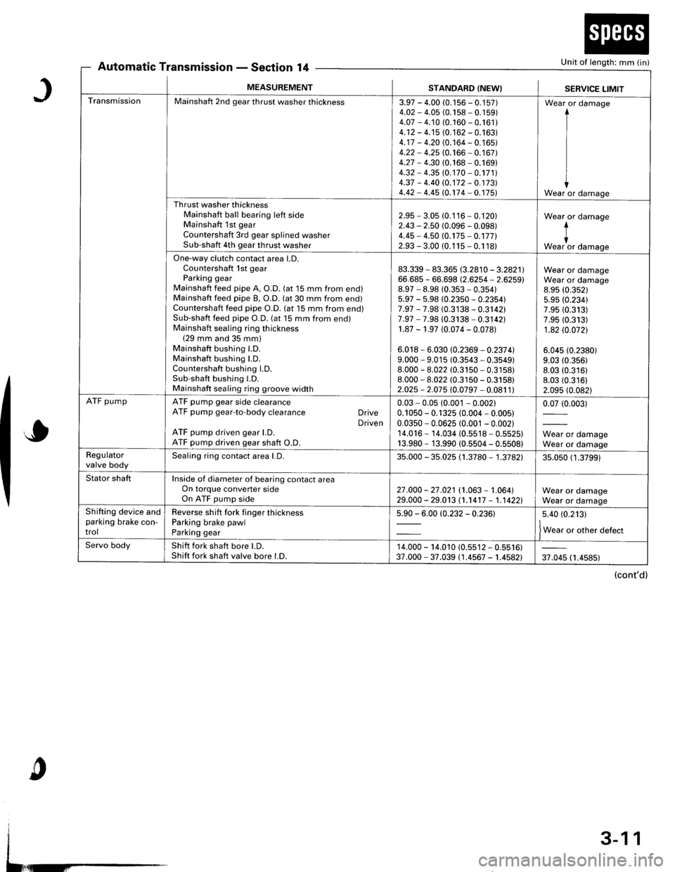
Automatic TransmissionSection 14Unit of length: mm (in)
J
o
c
MEASUREMENTSTANDARD (NEW}SERVICE LIMIT
TransmissionMainshaft 2nd gear thrust washer thickness3.97 - 4.00 (0.1 56 - 0.1 57)4.O2 - 4.05 (0.158 - 0. 1 59)4.07 - 4.10 (0.160 - 0.161 )4.12 - 4.15 (0. 1 62 - 0.163)4.17 - 4.20 (0. 164 - 0. 1 65)4.22 - 4.25 (0.166 - 0.167)4.27 - 4.30 (0.168 - 0. 169)4.32 - 4.35 (0. 170 - 0.171 )4.37 - 4.40 rc.172 - 0.17314.42 - 4.45 (0.174 - 0. 175)
Wear or damage
I
I
IWear or damage
Th rust washer thicknessMainshaft ball bearing left sideMainshaft 1st gearCountershaft 3rd gear splined washerSub-shaft 4th gear thrust washer
2.95 - 3.05 (0.116 - 0.120)2.43 - 2.50 (0.096 - 0.098)4.45 - 4.50 (0.175 - 0.17712.93 - 3.00 (0.1 15 - 0.1 18)
Wear or damage
*""1, damase
One-way clutch contact area l.D.Countershaft lst gearParking gearMainshaft feed pipe A, O.D. (at 15 mm from end)Mainshaft feed pipe B, O.D. (at 30 mm from end)Countershaft feed pipe O.D. (at 15 mm from end)Sub-shaft feed pipe O.D. (at 15 mm from end)Mainshaft sealing ring thickness(29 mm and 35 mm)Mainshaft bushing l.D.Mainshaft bushing LD.Countershaft bushing LD.Sub-shaft bushing l.D.Mainshaft sealing ring groove width
83.339 - 83.365 8.2810 - 3.2821166.685 - 66.698 (2.6254 - 2.6259)8.97 - 8.98 (0.353 - 0.35415.97 - 5.98 (0.2350 - 0.2354)7.97 - 7.98 (0.3138 - 0.3142)7.97 - 7.98 (0.3138 - 0.3142)1.87 - 1.97 (0.074 - 0.078)
6.018 - 6.030 (0.2369 - 0.237 4l9.000 - 9.015 (0.3543 - 0.3549)8.000 - 8.022 (0.3150 - 0.3158)8.000 - 8.022 (0.3150 - 0.3158)2.025 - 2.075 (0.0797 - 0.081 1)
Wear or damageWear or damage8.95 (0.352)
5.95 (0.234)7.95 (0.313)7.95 (0.313)
1.82 (0.0721
6.045 (0.2380)
9.03 (0.356)
8.03 (0.316)8.03 (0.316)
2.095 (0.082)
ATF pumpATF pump gear side clearanceATF pump gear-to-body clearance DriveDrivenATF pump driven gear l.D.ATF pump driven gear shaft O.D.
0.03 - 0.05 (0.001 - 0.00210.1 050 - 0. 1 325 (0.004 - 0.005)0.0350 - 0.0625 (0.001 - 0.002)14.016 - 14.034 (0.5518 - 0.5525)13.980 - 13.990 (0.5504 - 0.5508)
0.07 (0.003)
Wear or damageWear or damageRegulatorvalve bodySealing ring contact area l.D.35.000 - 35.025 (1 .3780 - 1 .3782135.050 (1 .3799)
Stator shaftInside of diameter of bearing contact areaOn torque converter sideOn ATF pump side27 .000 - 27 .021 (1.063 - 1.064)29.000 - 29.013 (1.1417 - 1,1 4221Wear or damageWear or damageShifting device andparking brake con-trol
Reverse shift fork finger thicknessParking brake pawlParking gear
5.90 - 6.00 (0.232 - 0.23615.40 (0.213)
f w"r, o, other defect
Servo bodyShift fork shaft bore LD.Shift fork shaft valve bore l.D.14.000 - 14.010 (0.s512 - 0.5516)37.000 - 37.039 (1.4567 - 1.4582)37.045 (1.4585)
(cont'd)
3-11