Page 1041 of 1681

J
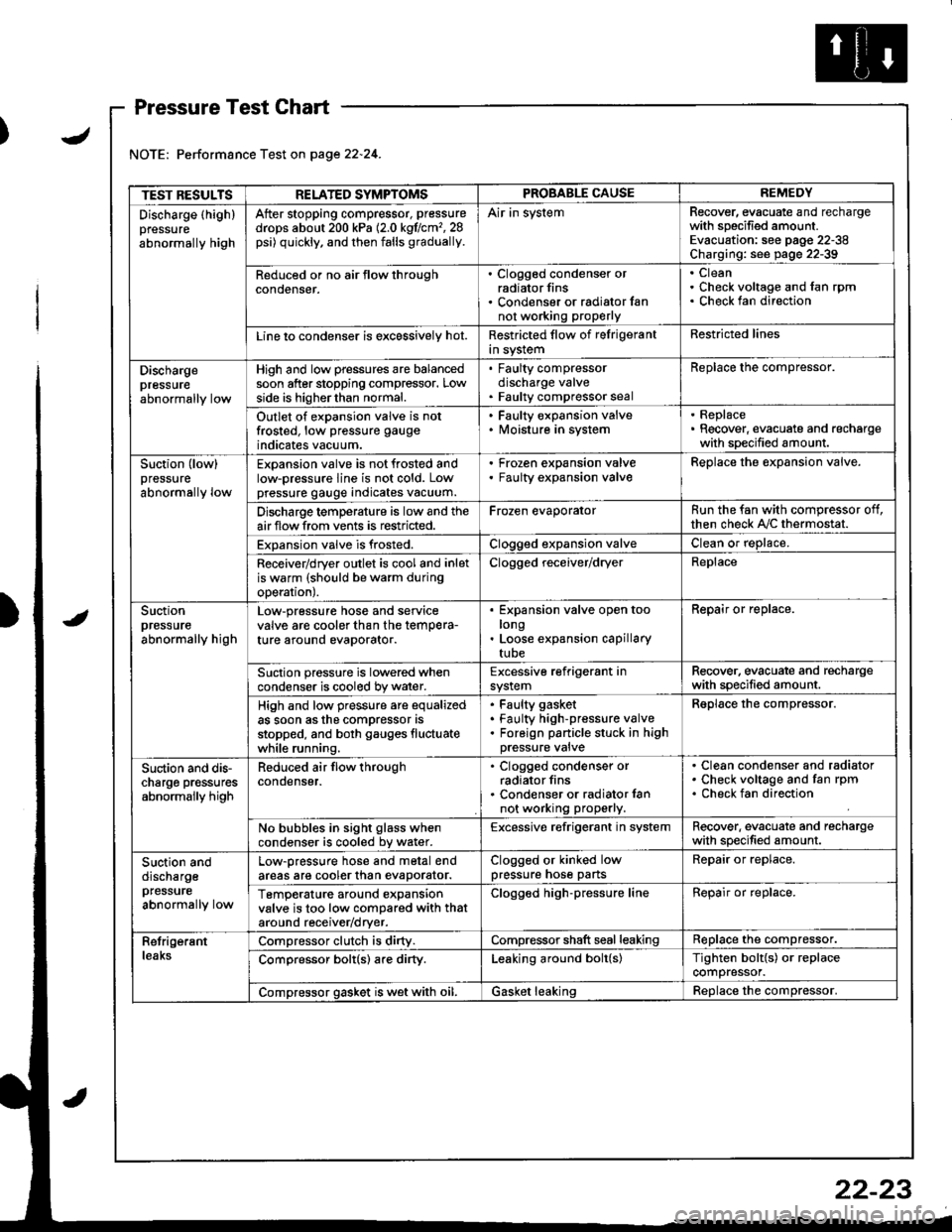
Pressure Test Chart
Performance Test on page 22.24.
TEST RESULTSRELATED SYMPTOMSPROBABLE CAUSEREMEDY
Discharge (highlpressure
abnormally high
After stopping compressor, pressure
drops about 200 kPa (2.0 kgflcm'�,28psi) quickly, and then falls gradually.
Air in systemRecover, evacuate and rechargewith specified amount.Evacuation: see pag€ 22-38Charging: see page 22-39
Reduced or no air tlow throughconoenser.
. Clogged condenser orradiator fins. Condenser or radialor fannot working proPerly
CleanCheck voltage and fan rpmCheck fan direction
Line lo condenser is excessively hot.Restricted flow of felrigerantin systemRestricted lines
Dischargepressureabnormally low
High and low pressures are balancedsoon after stopping compressor. Lowside is higherthan normal.
. Faulty compressordischarge valve. Faulty compressor seal
Replace the compressor.
Outlet of expansion valve is notfrosted, low pressure gauge
indicates vacuum.
. Faulty expansion valve. lvloisture in system
. Replace. Recover, evacuate and rechargewith specified amount.
Suction (low)pressure
abnormally low
Expansion valve is not frosted andlow-pressure line is not cold. Lowpressure gauge indicates vacuum.
Frozen expansion valveFaulty expansion valveReplace the expansion valve.
Discharge temperature is low and theairflow from vents is restricted.Frozen evaporatorRun the fan with compressor off,then check A,/C thermostat.
Expansion valve is frosted.Clogged expansion valveClean or replace.
Receiver/dryer outlet is cool and inletis warm (should be warm duringoperal|onJ.
Clogged receiver/dryerReplace
Suctionpressureabnormally high
Low-pressure hose and seryicevalve are cooler than the temPera-ture around evaporator.
Expansion valve open toolongLoose expansion capillarytube
Repair or replace.
Suction pressure is lowered whencondenser is cooled by water.Excessive refrigerant insystemRecover. evacuate and rechargewith specified amount.
High and low pressure are equalizedas soon asthe compressor asstopped, and both gauges fluctuatewhile running.
Faulty gasket
Faulty high-pressure valveForeign panicle stuck in highpressure valve
Reolace the comDressor.
Suction and dis-charge pr€ssuresabnormally high
Reduced air flow throughcondenser.
. Clogged condenser orradiator fins. Condenser or radiator lannot working properly.
Clean condenser and radiatorCheck voltage and fan rpmCheck fan direction
No bubbles in sight glass whencondenser is cooled bv water.Excessive refrigerant in systemRecover. evacuate and rechargewith specified amount.
Suction anddischargepfessure
abnormally low
Low-pressure hose and metal endareas are cooler than evaDorator.Clogged or kinked lowpressure hose partsRepair or replace.
TemP€rature around expansionvalve is too low compared with thataround receiv€r/dryer.
Clogged high-pressure lineRepair or replace.
RetrigerantleaksCompressor clutch is dirty.Compressor shaft seal leakingReplace the compressor.
Comoressor bolt(s) are dirty.Leaking around bolt(s)Tighten bolt{s) or replacecompressor.
Compressor gasket is wet with oil.Gasket leakingReolace the comoressor.
22-23
Page 1047 of 1681
lllustratedlndex
CLUTCHSETlnspection,Page 22-32
SNAP RING AReplace.
FIELD COILInspection, page 22-32
I / COMPRESSOR COMPLETE
.-- lDo not disassemble)
SUCTION SERVICE VALVEO.RINGReplace.
I
S..-
VX
I
I ^.-{\
I.ory
O.RINGReplace.RELICF VALVER€placement. page 22-34
22-29
Page 1048 of 1681

Compressor
Replacement
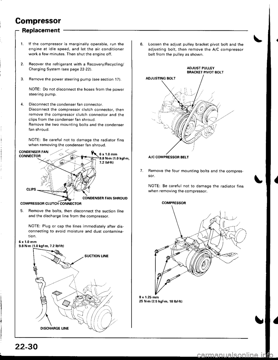
lf the compressor is marginally operable, run the
engine at idle speed, and let the air conditioner
work a few minutes. Then shut the engine off.
Recover the refrigerant with a Recovery/Recycling/
Charging System \see page 22-22).
Remove the power steering pump (see section 17).
NOTE: Do not disconnect the hoses from the power
steering pump.
Disconnect the condenser fan connector.
Disconnect the compressor clutch connector, then
remove the compressor clutch connector and the
clips from the condenser fan shroud
Remove the two mounting bolts and the condenser
fan shroud.
NOTE: Be careful not to damage the radiator fins
when removing the condenser fan shroud.
1.0 mmN.m (1.0 kgt.m,rbf.ftt
CONDENSER FAN SHROUD
COMPRESSOR CLUTCH CONNECTOR
5. Remove the bolts, then disconnect the suction line
and the discharge line from the compressor.
NOTE: Plug or cap the lines immediately aiter dis-
connecting to avoid moisture and dust contamina-
tio n.
6x1.0mm9.8 N.m (1.0 kgf.m, 7.2 lbf.ft)
22-30
6. Loosen the adjusl pulley bracket pivot bolt and the
adjusting bolt, then remove the A/C compressor
belt from the Dullev as shown.
ADJUSTING BOLT
A/C COMPRESSOR BELT
Remove the four mounting bolts and the compres-
sor.
NOTE: Be careful not to damage the radiator fins
when removing the compressor.
7.
./.,
COMPRESSOR
Page 1050 of 1681
Compressor
Clutch Inspection
Check the plated parts of the pressure plate for color
changes, peeling or other damage. lf there is dam-
age, replace the clutch set.
Check the pulley bearing play and drag by rotating
the pulley by hand. Replace the clutch set with a new
one if it is noisy or has excessive play/drag.
Measure the clearance between the Dullev and thepressure plate all the way around. lf the clearance is
not within specified limits, the pressure plate must beremoved and shims added or removed as required,following the procedure on page 22-33.
Clearanca: 0.50 t 0.15 mm (0.020 r 0.006 in)
NOTE; The shims are available in three thicknesses:
0.1 mm, 0.3 mm and 0.5 mm.
22-32
Check resistance of the field coil.
Field Coil Resistance: 3.6 1 0.2 ohm at 68'F {20'C)
lf resistance is not within specifications, replace the
field coil.
Page 1051 of 1681
J
Glutch Overhaul
1. Remove the center bolt while holding the pressure
plate,
A/C CLUTCH HOLDER
lCommorcially available)Robinair: P/N 1020,1
Kent-Moor6: P/N J37872
2.
CENTER BOLT13.2 N.m {1.35 kgf m,9 76lbtft)
IRemove the pressure plate and shim(s) taking
not to lose the shim(s).
sHtM(sl
[4
3. Remove the snap ring B with a snap ring pliers,
then remove the pulley.
NOTE:
o Be careful not to damage the pulley and com-
pressor during removal/installation.
. Once the snap ring B is removed, replace it with
a new one.
(cont'd)
I
/ T-\vr= ...--.-
-ffitll---.\lr l,
\-l I .v
22-33
Page 1052 of 1681

Compressor
a
a
Clutch Overhaul (cont'dl
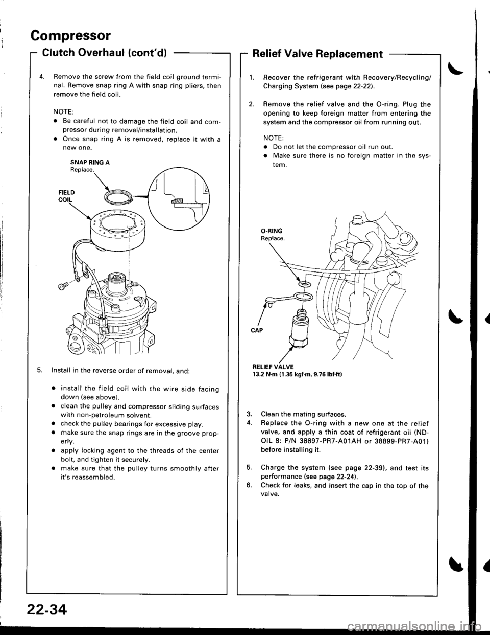
Remove the screw from the field coil ground termi,
nal. Remove snap ring A with snap ring pliers, then
remove the field coil.
. Be careful not to damage the field coil and com-presso. during removal/installation.
. Once snap ring A is removed, replace it with a
SNAP RING AReplace.
5. Install in the reverse order of removal, andl
install the field coil with the wire side facing
down (see above).
clean the pulley and compressor sliding surfaceswith non-petroleum solvent.
check the pulley bearings for excessive play.
make sure the snap rings are in the groove prop-
efly.
apply locking agent to the threads of the center
bolt, and tighten it securely.
make sure that the pulley turns smoothly after
it's reassembled.
Relief Valve Replacement
Recover the refrigerant with Recovery/Recycling/
Charging System lsee page 22-221.
Remove the relief valve and the O-ring. Plug the
opening to keep foreign matter from entering the
system and the compressor oil from running out,
NOTE:
. Do not let the compressor oil run out.
. Make sure there is no foreign matter in the sys-
tem.
RELIEF VALVE13.2 N.m (1.35 kgf.m,9.76lbtft)
3. Clean the mating surfaces.
4. Replace the O-ring with a new one at the relief
valve, and apply a thin coat of refrigerant oil (ND-
OIL 8: P/N 38897-PR7-A01AH or 38899-PR7-A01)
before installing it.
5. Charge the system (see page 22-39), and test itsperformance (see page 22-241.
6. Check for leaks, and insert the cap in the top of the
FIELD
t\I lu
B _t_:---\-lr
\,/
22-34
Page 1064 of 1681
Relay and Control Unit Locations
Engine Compartment
ABS PUMP MOTORRELAY
FAN RELAY
UNDER.HOOD AB{iFUSE/RELAY BOXIKG mod.ll
A/C COMPRESSORCLUTCH RELAYRADIATORFAN BELAY
UNDER.H(X)DFUSE/RELAY BOX
A&S MODULAUNIT
UNDER.HOOD ABII FUSE,/RELAY BOX {KE modoll
----ar:l
--r: u
D
tr
L]
ABS PUMP MOTOR
23-7
Page 1071 of 1681

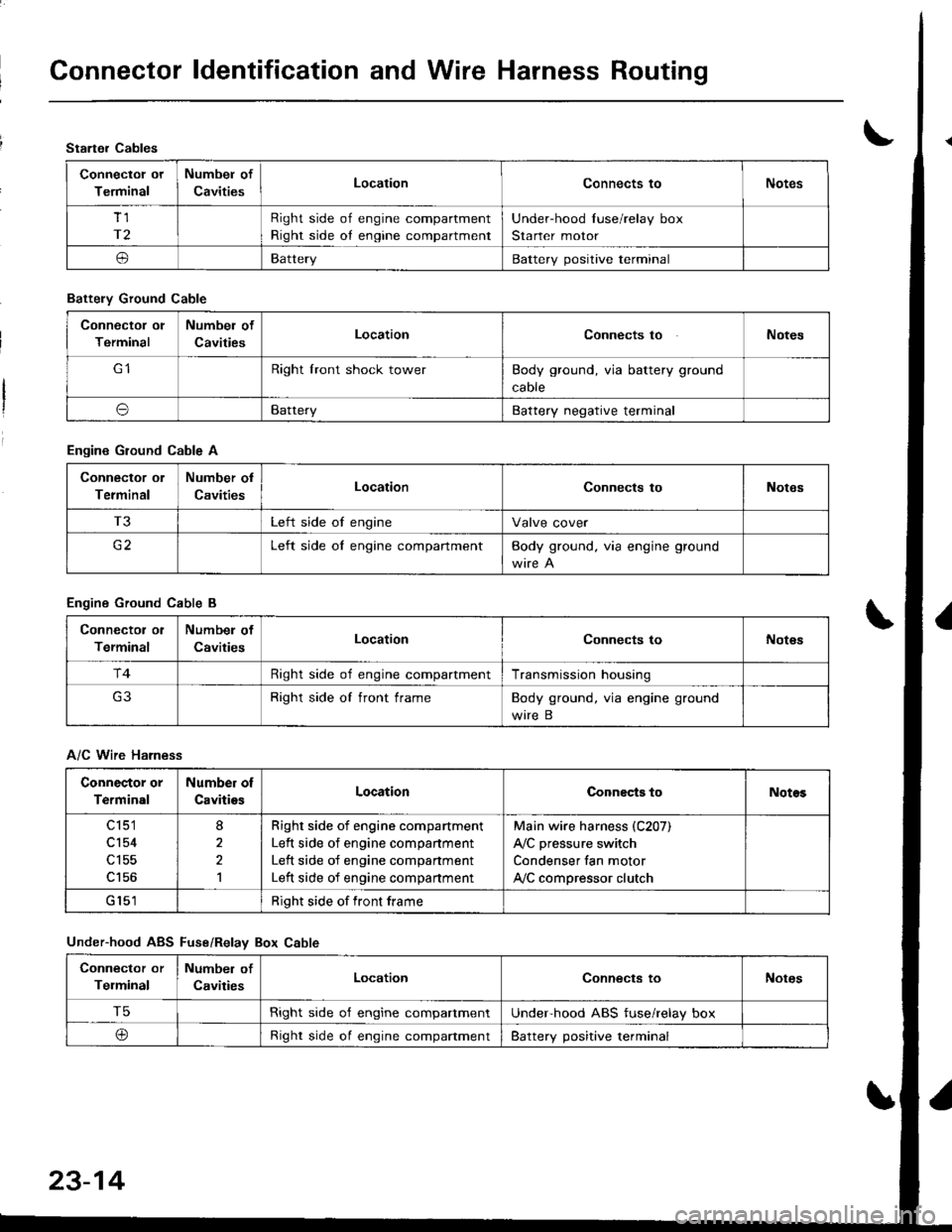
Connector ldentification and Wire Harness Routing
Starter Cables
Connectol ot
Terminal
Numbel of
CavitiesLocationConnects toNotes
Tl
r2
Right side of engine compartment
Right side oI engine compartment
Under-hood Iuse/relay box
Starter motor
oBatteryBattery positive terminal
Battely Ground Cable
Connector ol
Terminal
Numbel of
CavitiesLocationConnects toNotes
Right lront shock towerBody ground, via battery ground
caore
oBatteryBattery negative terminal
Engine Ground Cable A
Connector ol
Terminal
Number ol
CavitiesLocationConnects toNotes
T3Left side of engineValve cover
c2Left side oI engine compartmentBody ground. via engine ground
Engine Ground Cable B
Connector ol
Terminal
Numbel of
CavitiesLocationConnects toNot€s
r4Right side of engine compartmentTransmission housing
Right side of front frameBody ground, via engine ground
wire B
A/C Wire Harness
Connector or
Terminal
Number of
CavitiesLocationConnects toNotos
c 151
cl54
c156
8
2,l
Righr side of engine compartment
Left side of engine companment
Left side of engine compartment
Left side of engine compartment
Main wire harness (C207)
A,/C pressure switch
Condenser fan motor
ly'C compressor clutch
Right side of front frame
Under-hood ABS Fuse/Relav Box Cable
Connector or
Telminal
Number of
CavitiesLocationConnects toNotes
T5Right side o'f engine compartmentUnderhood ABS fuse/relay box
@Right side oI engine compaftmentBattery positive terminal
23-14