1998 HONDA INTEGRA battery
[x] Cancel search: batteryPage 1375 of 1681
)6.
7.
8.
Connect a 12 volt battery to the tool:
. lf the green light on the tool comes on, the alr-
bag igniter circuit is defective and cannot deploy
the airbag. Go to Damaged Airbag Specia I
Procedure.
. lfthe red light on the tool comes on, the airbag is
ready to be deployed.
Push the tool's deployment switch The airbag
should deploy (deployment is both highly audible
and visible; a loud noise and rapid inflation of the
bag, followed by slow deflation).
. lf the airbags deploy and the green light on the
tool comes on, continue with this procedure
. lf an airbag doesn't deploy. yet the green light
comes ON, its igniter is defective. Go to Dam-
aged Airbag Special Procedure.
!!@ During deployment, the airbag c8n
become hot enough to burn you Wait thirtY min-
ut€s after d€ployment befote touching the assem-
blv.
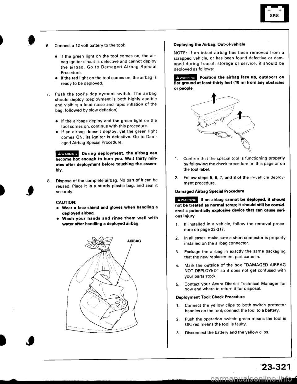
Dispose of the complete airbag. No part of it can be
reused. Place it in a sturdy plastic bag, and seal it
securery.
CAUTION:
. wear a lace shield and gloves when handling a
deployed airbag.
. Wash your hands and rinse them well with
water after handling a deployed sirbag
)
Deploying the Airbag: Out-ot-vehicle
NOTE: lf an intact airbag has been removed from a
scraDDed vehicle, or has been found defective or dam-
aged during transit, storage or service, it should be
deoloved as follows:
@@ Position th€ airbag laca up. outdoors on
tlat ground at l€ast thirty leet (10 m) ftom any obstacles
or people.
1. Confirm that the special tool is functioning properly
by tollowing the check procedure on thls page or on
the tool lab€|.
2. Follow steps 5, 6, 7, and 8 ol the in.vehicle deploy'
ment orocedure.
Damaged Airbag Sp€citl Procedurc
!@ [ an airbag cannot be d.ploytd, h 3hoold
not be lreated as normal scrap; it should 3till b. corlrkl
ered a polentially sxplosive device that can clura tari
ous iniury.
1. lf installed in a vehicle, follow the removal proce-
dure on page 23-317.
2. ln all cases, make sure a short connector is properly
installed on the airbag connector.
3. Package the airbag in exactly the same packaging
that the new replacement part came In.
4. Mark the outside of the box "DAMAGED AIRBAG
NOT DEPLOYED" so it does not get confused with
your Parts stock.
5. Contact your Acura District Technical lvanager for
how and where to return it for disposal.
Deployment Tool: Ch€ck Ptocedure
1. Connect the yellow clips to both switch protector
handles on the tool; connect the tool to a battery
2. Push the operation switch: green means the tool is
OK; red means the tool is faultv.
3. Disconnect the battery and the yellow clips
23-321
Page 1376 of 1681
Cable Reel
Replacement
@ store a removed airbag with the pad sur-
tac€ up. lf the airbag is improperly stored face down,
.ccidontal dcployment could propel the unit with
.nough torce to cause serious injury.
CAUTIONT
o Carefully insp€ct the airbag belore installing it. Do
not install an airbag that shows signs of boing
dropped or improperly handled, such as dents,
cracks or deformation.
. Always disconnect the airbag connector(s) when the
harness is disconnectod.
. Do not disassemble or tamper wiih the airbag.
1. Make sure you have the anti-theft code for the radio,
then write down the frequencies for the radio's pr+
set button.
2. Disconnect the battery negative cable, then discon-
nect the positive cable from the battery. and wait at
least three minutes,
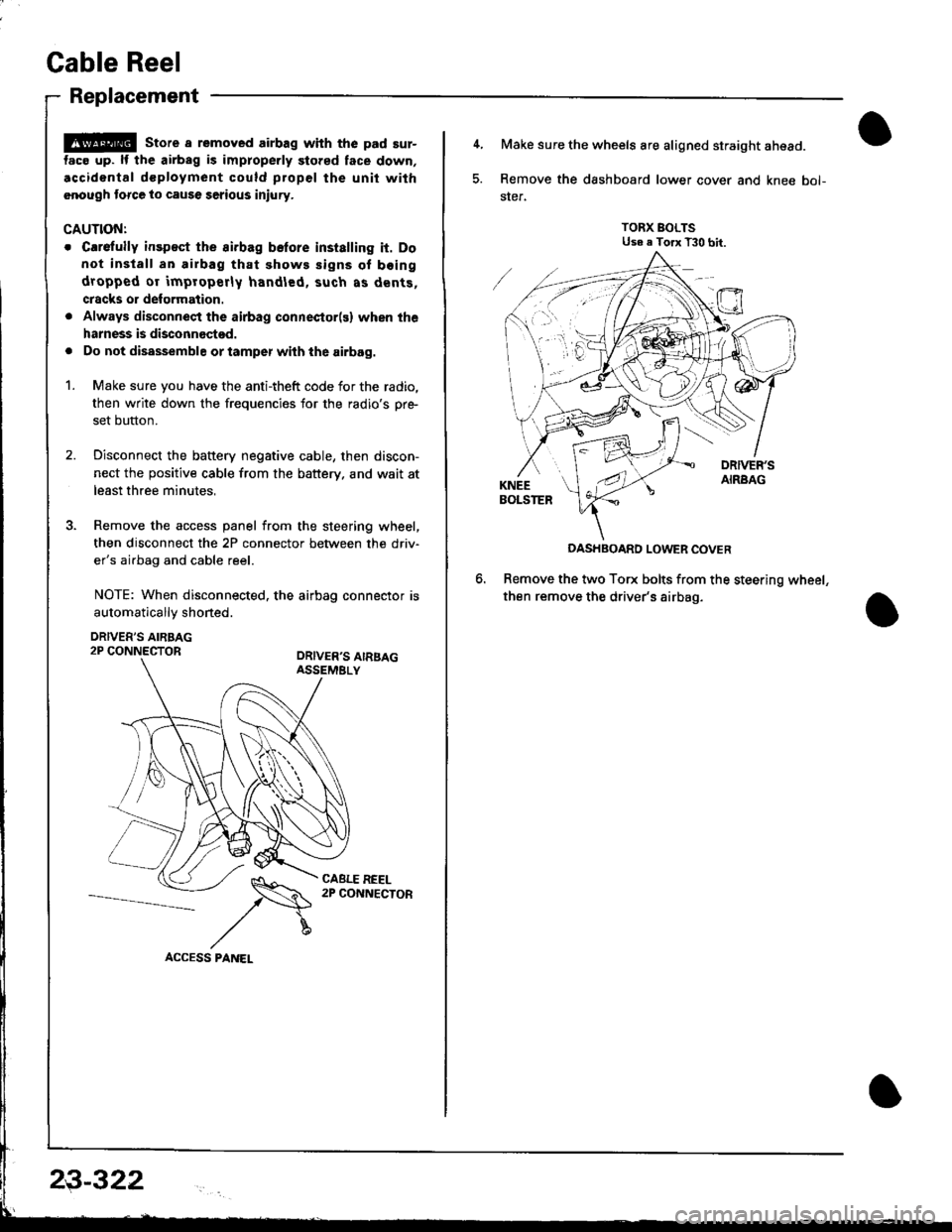
3. Remove the access panel from the steering wheel,
then disconnect the 2P connector between the driv'
er's airbag and cable reel.
NOTE: When disconnected. the airbag connector is
automaticallv shoned.
DRIVER'S AIRBAG2P CONNECTORORIVER'S AIRSAGASSEMELY
CABLE REEL2P CONNECTOR
23-322
4, Make sure the wheels are aligned straight ahead.
5. Remove the dashboard lower cover and knee bol-
ster.
TORX BOLTSUse e Torx T30 bit.
DASHBOARD LOWER COVER
Remove the two Torx bolts from the steering wheel,
then remove the driver's airbag.
Page 1379 of 1681
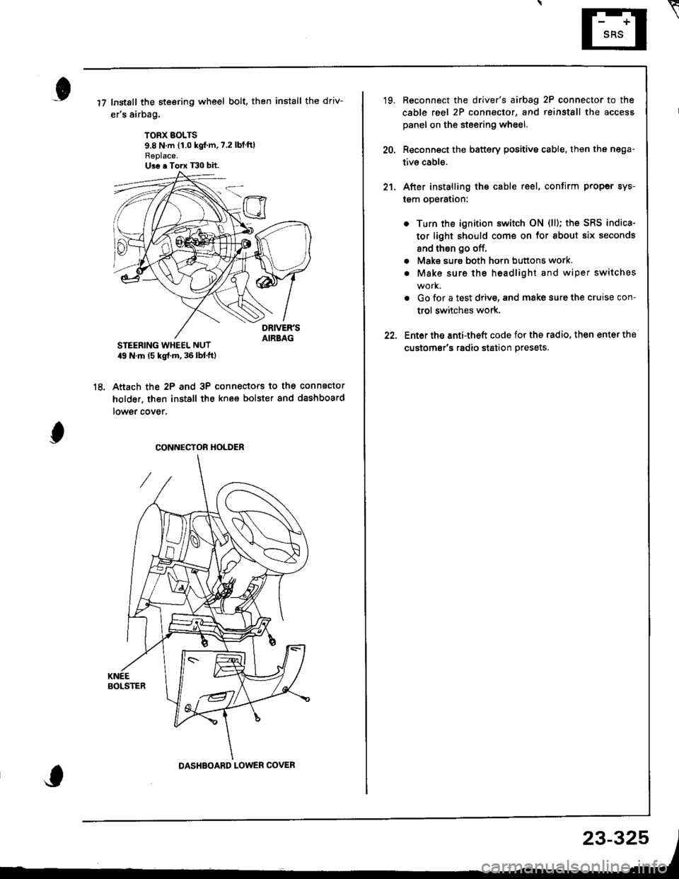
Instsll the steering wheel bolt, then install the driv-
er's airbag.
TORX BOLTS9.8 N m {1.0 kgf'm,7.2 lbtftlReplace.U3e . Torx T30 bit.
STEERING WHEEL NUT19 N.m (5 kgl.m, 36 lbl.ftl
Anach the 2P and 3P connectors to the connector
holder. then install the knee bolster and dashboard
lowgr cover,
le
CONNECTOR HOLDER
DASHBOARD LOWER COVER
23-325
\
'19. Reconnect the driver's aibag 2P connector to the
cable reel 2P connector, and reinstSll the access
panel on the steering wheel.
20, Reconnect the battery positive cable, then the nega-
tivs cable.
21. After installing the cable reel, confirm proper sys-
tgm operation:
Turn the ignition switch ON (ll); the SRS indica-
tor light should come on for about six seconds
and thsn go off.
Make surs both horn buttons work.
Make sure the headlight and wiper switches
Go {or a test drive, and make sure the cruise con-
trol switches work.
Ent6r the anti-theft code for tho radio, then enter the
customsr's radio station presets.
a
a
Page 1380 of 1681
SRS Unit
Replacement
CAUNON:
. Betore disconnecting the SRS main harness 18P con-
nector, disconnect the aitbag connectors.
. During installation or replacement, do not bump
(impact wrench, hammer etc.) the al€a near the SRS
unit.
. Do not damage the SRS unit terminals or connec-
tors.
. Do not disassemble the SRS unit; it has no service-
able parts.
. Store the SRS unit in a clean, dry area.
. Do not use any SRS unit which has been subiected
to water damage or shows signs of being dtopped ol
improperly hsndled, such as dents, cracks or detor-
mation.
Disconnect the baftery negative cable, then discon-
nect the positive cable from the battery, and wait at
least three minutes.
Disconnect the airbag connectors. (When discon-
nected. the airbag connectors are automatically
shorted.)
Driver's Side:
. Remove the access panel from the steering
wheel, then disconnect the 2P connector
between the driver's airbag and cable reel (see
page 23-285).
Front Passenger's Side:
. Disconnect the 2P connector between the front
passenger's airbag and SRS main harness (see
page 23-285).
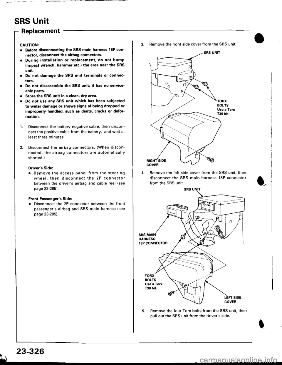
3. Remove the right side cover from the SRS unit.
SRS UNIT
TORXBOLTSUse a TorxT30 bir.
SIDEcovEn
4. Remove the left side cover from the SRS unit, then
disconnect the SRS main harness 18P connector
from the SRS unit.
sRsHARNESS18P CONNECTOR
t
TORXBOLTSU36 a ToaxT30 bh.
SIDECOVER
Remove the four Torx bolts from the SRS unit, then
pull out the SRS unit from the driver's side.
23-326?\
SRS UNIT
Page 1381 of 1681
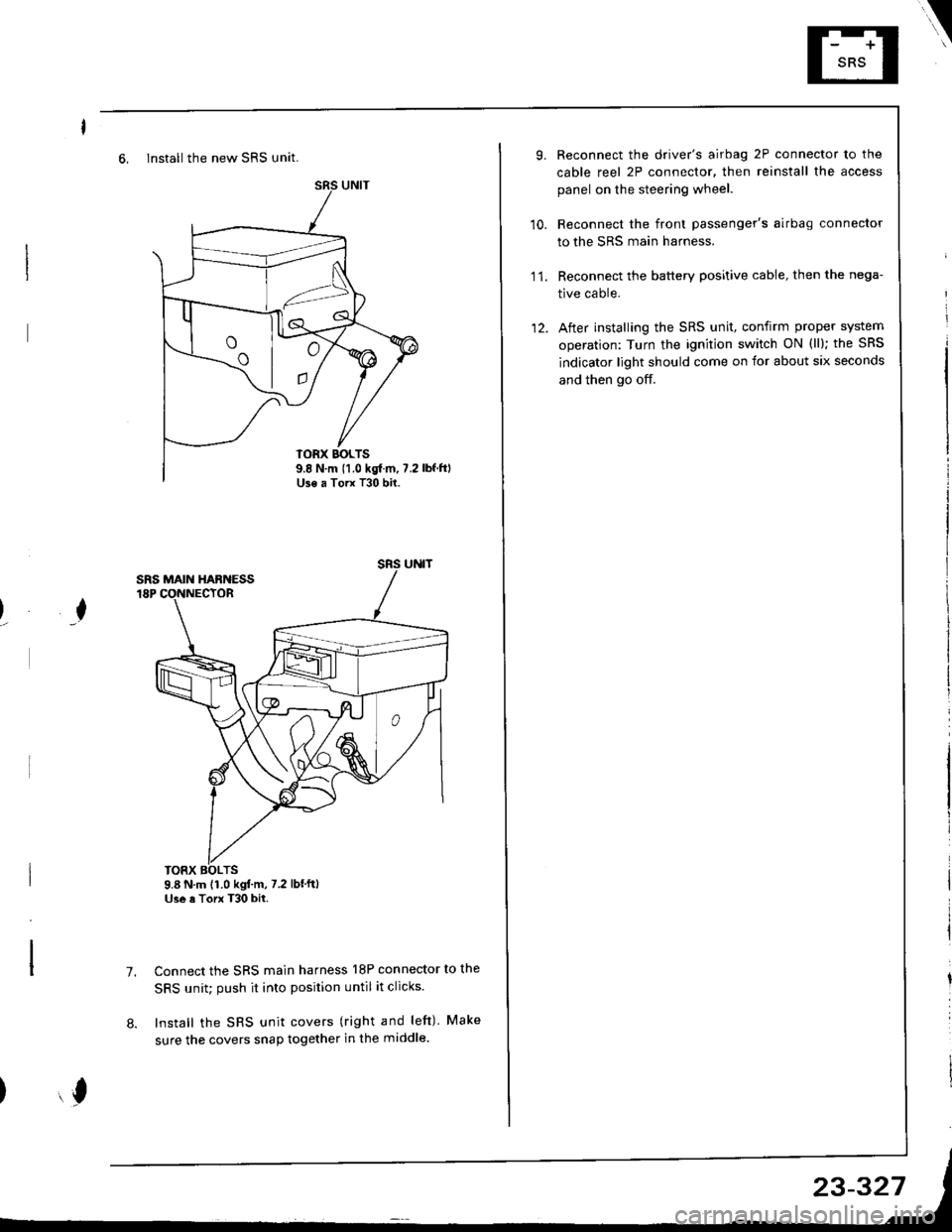
6, Install the new SRS unit.
o^ l- o
9.8 N.m 11.0 kgf m, 7.2Use a Torx T30 bit.
I
TORX BOLTS9.8 N.m 11.0 kgl.m, 7.2 lbf'ftlUse a Torx T30 bit.
7.Connect the SRS main harness l8P connector to the
SRS unit; push it into position until it clicks.
Install the SRS unit covers (right and left) Make
sure the covers snap together in the middle.8.
,l
\
10.
Reconnect the driver's airbag 2P connector to the
cable reel 2P connector, then reinstall the access
panel on the steering wheel.
Reconnect the front passenger's airbag connector
to the SRS main harness.
Reconnect the battery positive cable, then the nega-
tive cable.
After installing the SRS unit, confirm proper system
operation: Turn the ignition switch ON (ll); the SRS
indicator light should come on for about six seconds
and then go off.
11.
12.
Page 1383 of 1681
).1
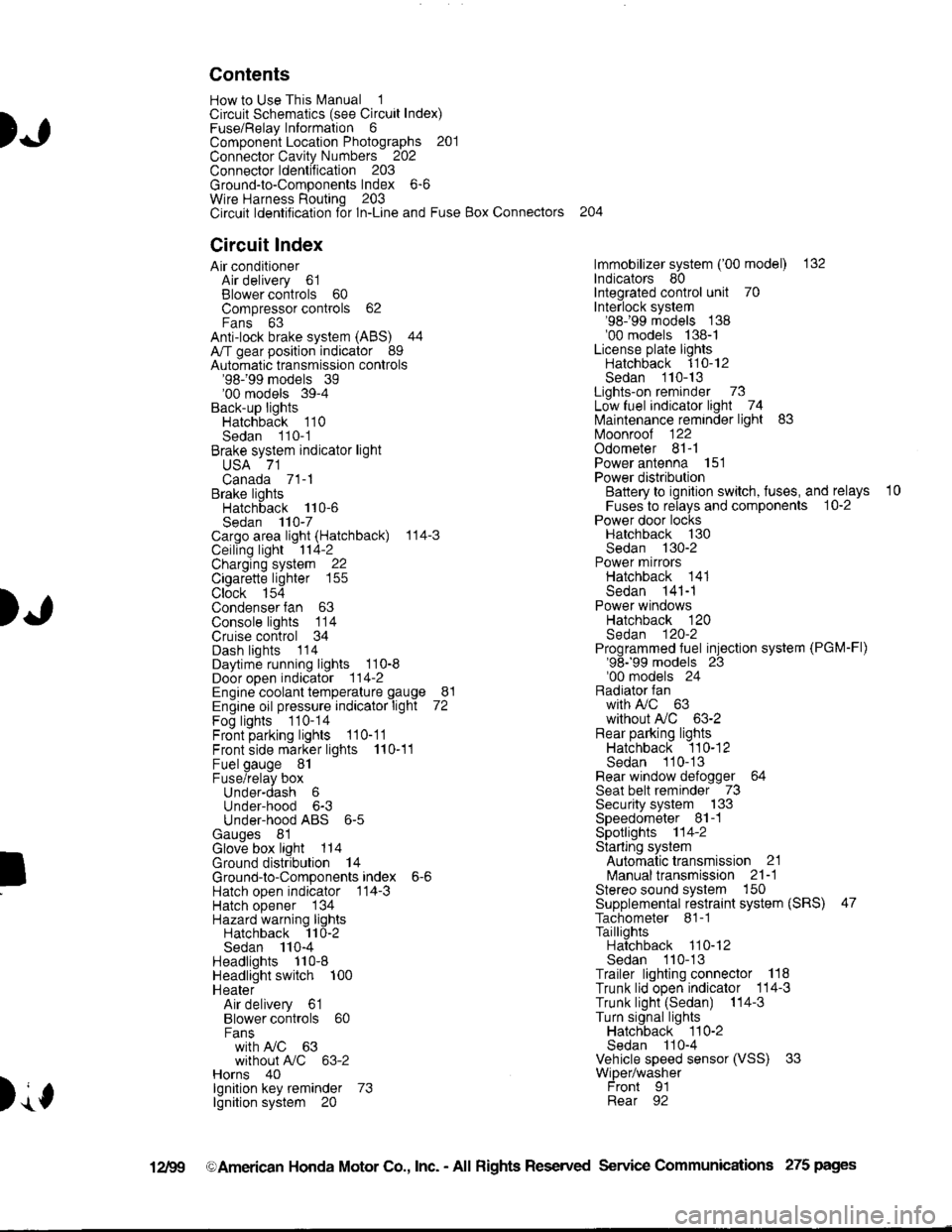
Contents
How to Use This l\.4anual 1Circuit Schematics (see Circuit Index)Fuse/Relaylnformation 6ComponentLocation Photographs 201
Connector Cavity Numbers 202Connectorldentification 203
Ground-to-Components Index 6-6Wire Harness Routing 203Circuit ldentification lor ln-Line and Fuse Box Connectors
Circuit Index
Air conditionerAir delivery 61Blower controls 60Compressor controls 62Fans 63Anti-lock brake system (ABS) 44A/T gear position indicator 89Automatic transmission controls'98199 models 39'00 models 39-4Back-up lightsHatchback 110Sedan 110- 1Brake system indicator light
USA 71Canada 71-1Brake lightsHatchback 110-6Sedan 110-7Cargo area light (Hatchback) 114-3Ceiling light 114-2Charging system 22Cigarette lighter 155
Clock 154Condenser fan 63Console lights 114Cruise control 34Dash lights 1 14Daytime running lights 110-8Door open indicator 114-2Engine coolant temperature gauge 81Engine oil pressure indicator light 72Fog lights 110-14Front parking lights 110-11Front side marker lights 110-11Fuel gauge 81Fuse/relay boxUnder-dash 6Under-hood 6-3Under-hood ABS 6-5Gauges 81Glove box light 114Ground distribution 14Ground-to-Componentsindex 6-6Hatch open indicator '114-3
Hatch opener '134
Hazard warning lightsHatchback 'l l0-2Sedan 110-4Headlights 1'10-8Headlight switch 100HeaterAir delivery 61Blower controls 60Fanswith A,/C 63without A,/C 63-2Horns 40lgnilion key reminder 73lgnition system 20
204
lmmobilizer system ('00 model) 132lndicators 80Integrated control unit 70Interlock system'98199 models 138'00 models 138-1License plate lightsHatchback 110-12Sedan 110-13Lights-on reminder 73Low fuel indicator light 74l\,4aintenance reminder light 83l\iloonroof 122Odometer 81-1Power antenna 151Power distributionBattery to ignilion switch, fuses, and relays
Fuses to relays and components 10-2Power door locksHatchback '130
Sedan 130-2Power mirrorsHatchback 141Sedan 141-1Power windowsHatchback 120Sedan 120-2Programmed fuel injection system (PGM-Fl)'98199 models 23'00 models 24Radiator fanwith tuC 63without A,/C 63-2Rear parking lightsHatchback 110-12Sedan 110- 13Rear window defogger 64Seat belt reminder 73Security system 133Speedometer Il-1Spotlights 114-2Starting syslemAutomalictransmission 21l\.4anualtransmission 21-1Stereo sound system 150Supplemental restraint system (SRS) 47Tachometer 81- 1TaillightsHatchback 110-12Sedan 110-13Trailer lighting conneclor 118Trunk lid open indicator 114-3Trunk light (Sedan) 114-3Turn signal lightsHatchback 110-2Sedan 110-4Vehicle speed sensor (VSS) 33Wiper/washerFront 91Rear 92
10
).1
I
Xr
12Fg oAmerican Honda Motor Co., Inc. - All Rights Reserved Service Communications 275 pages
Page 1386 of 1681
)o
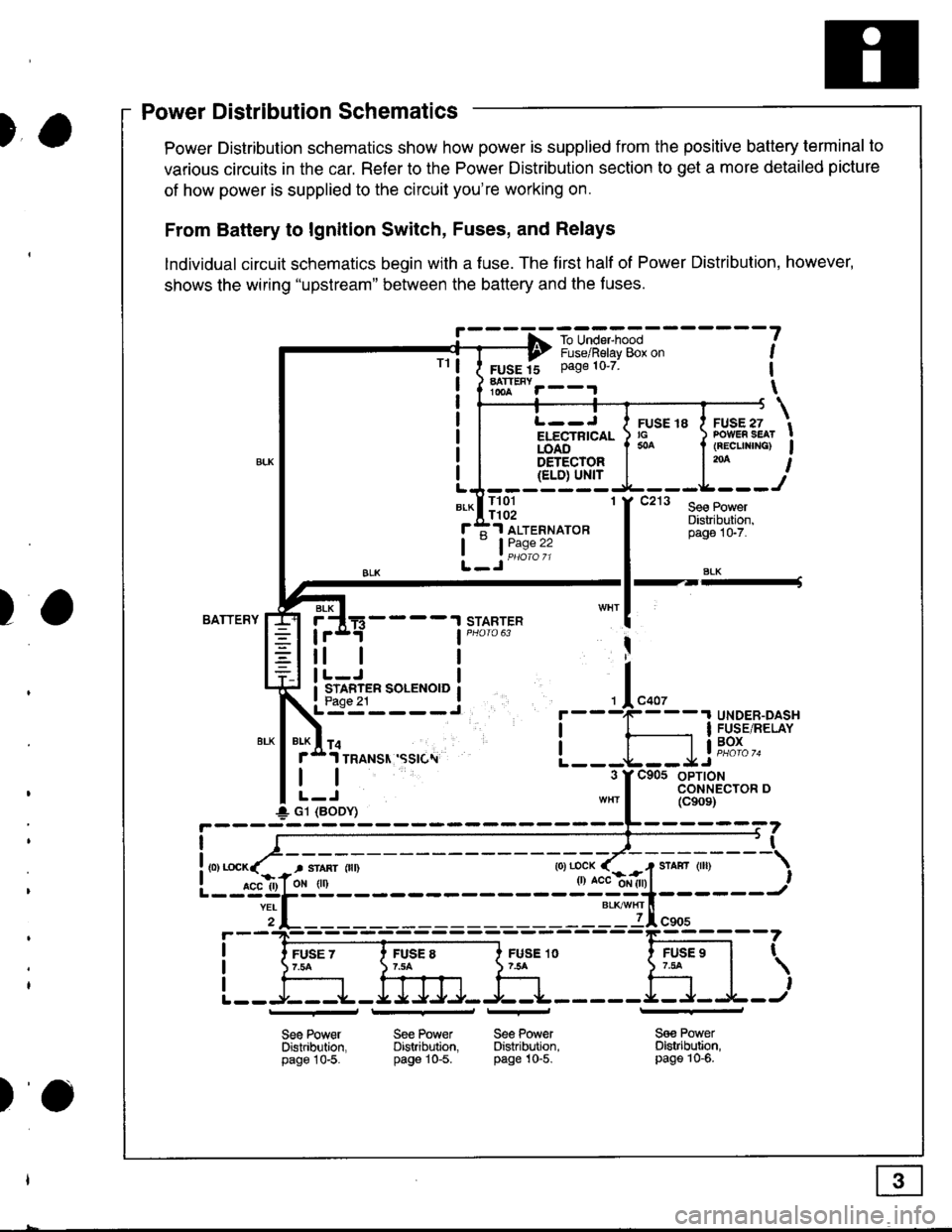
)a
)wer IJrstnDullon Scnemallcs -
Power Distribution schematics show how power is supplied from the positive battery terminal to
various circuits in the car. Refer to the Power Distribution section to get a more detailed picture
of how power is supplied to the circuit you're working on.
From Battery to lgnition Switch, Fuses, and Relays
lndividual circuit schematics begin with a fuse. The first half of Power Distribution, however,
shows the wiring "upstream" between the battery and the f uses.
!' - - - -f -ro-unE,-"*l - - - - - - -
?---? i,"-")il"i"v-g& o" ,
FUSE 15 Page 10'7 1
hTt""r--.r \
TrL--J I ruse re I ruse zi/ ru:rE ro a .v-E., tELECTRTCAL ) rc ) PowER sEAr !iOA6".'-'- I * I (REcuNrNG) Igs-r-qqrg! | l'* I{ELD) Ul'{rLJ-------
*-lll3l 'f t"' l*.r:::f ;1 ALTERNAToR
tL_Jii1:"":
Distribuiion,pago 1G7.
SLK
BATTERYSTARTERBLK
4----t
tl
STARTER SOLENOID
I
I
+ G1 (BODY)
r
I
I
I
FUSE 1O754
Sge PowerDistribltion,page 10-5.
FUSE 97.tat
,
l---r+J
See Power Se€ PowerDistribution. Distribution.page 10-5. pag€ 10-5.
_l_
Sa€ PowerDistribution,page 10-6.
Power Distribution Schematics
tt
)o
Page 1394 of 1681
'l'
Five-Step Troubleshooting
1. Verify The Complaint
Turn on all the components in the problem
circuit to check the accuracy of the customer
complaint. Note the symptoms. Do not begin
disassembly or testing until you have
narrowed down the Problem area.
2. Analyze The Schematic
Look up the schematlc for the problem
circuit. Determine how the circuit is
supposed to work by tracing the current
paths from the power source through the
circuit components to ground. Also, trace
circuits that share wiring with the problem
circuit. The names of circuits that share the
same fuse, ground, or switch, and so on' are
referred to in each circuit schematic. Try to
operate any shared circuits you didn't check
in steo 1. lf the shared circuits work, the
shared wiring is OK, and the cause must be
in the wiring used only by the problem
circuit. lf several circuits fail at the same
time, the fuse or ground is a likely cause.
Based on the symptoms and Your
understanding of the circuit's operation,
identify one or more possible causes.
3. lsolate The Problem By Testing The Circuit
Make circuit tests to check the diagnosis
you made in step 2. Keep in mind that a
logical, simple procedure is the key to
eff icient troubleshooting. Test for the most
likely cause of failure f irst. Try to make tests
at points that are easily accessible.
4. Fix The Problem
Once the specific problem is identified,
make the repair. Be sure to use proper tools
and safe procedures.
5. Make Sure The Circuit Works
Turn on all components in the repaired
circuit in all modes to make sure you've
fixed the entife problem. lf the problem was
a blown f use, be sure to test all of the
circuits on that {use. Make sure no new
problems turn up and the original problem
does not recur.
Test Equipment
CAUTION:
Most circuits include solid-state devices.
Test the voltages in these circuits only with
a 1o-megaohm or higher impedance digital
multimeter. Never use a test light or analog
meter on citcuits that contain solid-state
devices. Damage to the devices may result.
Test Light and DVOM
On circuits without solid-state devices, use a
test light to check for voltage. A test light is
made up of a 12 volt bulb with a pair of leads
attached. After grounding one lead, touch the
other lead to various points along the circuit
where voltage should be present. The bulb
will go on i{ there is voltage at the point being
tested. lf you need to know how much
voltage is present, use a digital
volVohmmeter (DVOM).
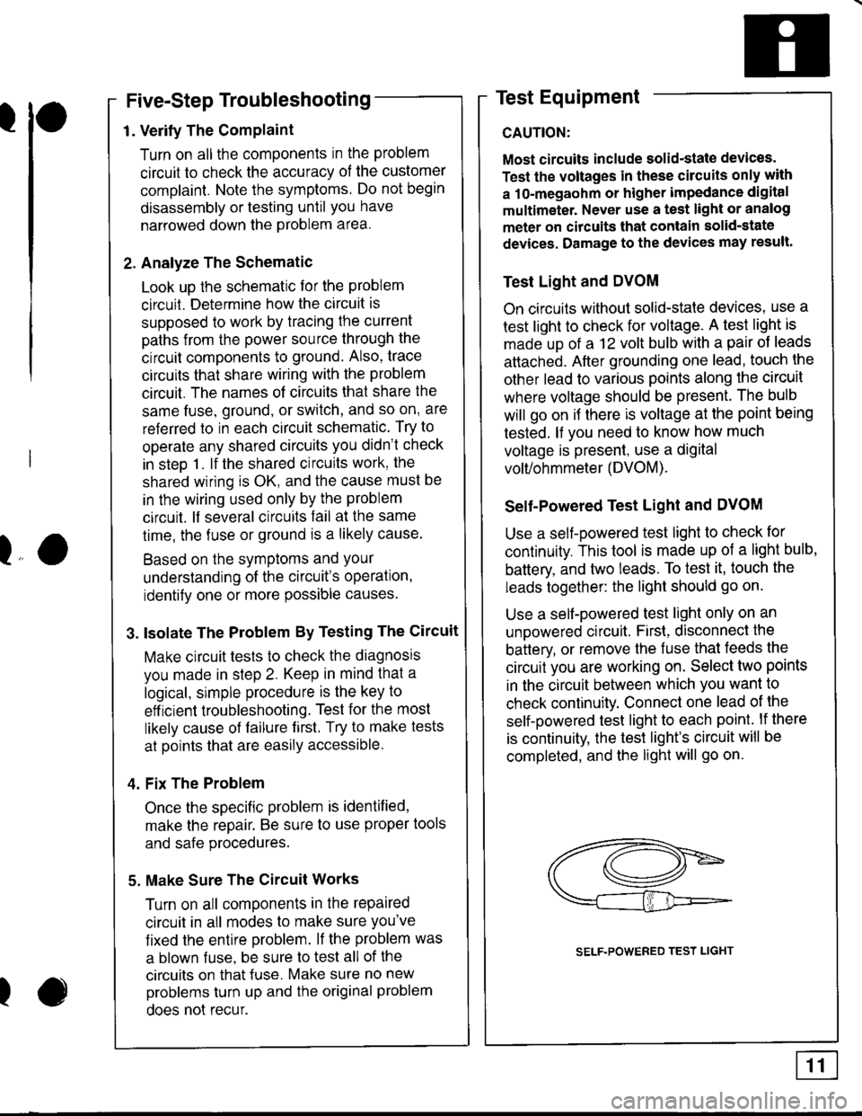
Selt-Powered Test Light and DVOM
Use a self-powered test light to check for
continuity. This tool is made up of a light bulb,
battery, and two leads. To test it, touch the
leads together: the light should go on.
Use a self-powered test light only on an
unoowered circuit. First, disconnect the
battery, or remove the fuse that feeds the
circuit you are working on. Select two points
in the circuit between which you want to
check continuity. Connect one lead ol the
self-powered test light to each point. lf there
is continuity, the test light's circuit will be
completed, and the light will go on.
lo
I
SELF.POWERED TEST LIGHT