Page 1543 of 1681
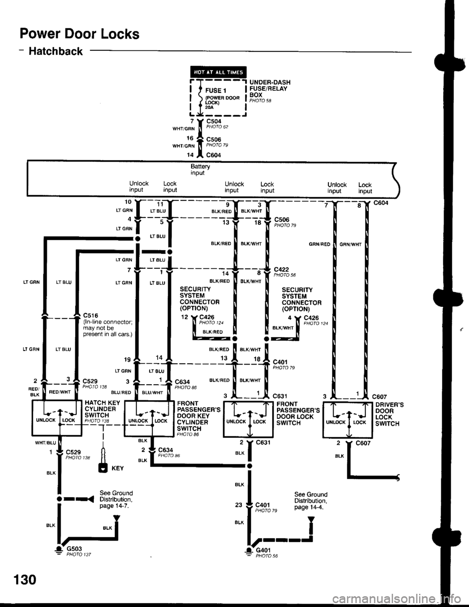
Power Door Locks
- Hatchback
T(
t.x
'o""f "
I
t" lf r8 lf e-l'-d;7o
-: --=--
I ",*".o ! "."*n., ! o"n",,
-l=+------+--,J,*.^
Lrcnr
I
tt "tu
l ar"u*,t
"LK FED
I
BLK*HT
I aa"ur,r,
I l3['"l,ii'o' I l3['*1,1t'o'
P,:r:-.^^--^,^.1 llTl'""'�
I I (oP'oN)
l'**'**"::;l | @! !:lX'**'-
'' "'i
[.'{,f - - - - =-d$*--T;.
- - - -
gl "":l ",*:.:["."::["*^ ."n",.1."n,n",
_.{____"lit':l;j".,,
^l .,"";1;,;.;T-------T--T*o',
;"*f t*t," "., ".'" ft;-if,
9,1#,, *- ^';tri::li
"..,
i "*l _ 2y
g:fi;"",," [l il'"8%," "* I-;
l-l
I s"" erouno
Bt^
|a r-< Diskibution. I see Ground
. oaoe 14-7. ,. J coot P:"^T1T19"'
I
n"o" t+ z ,"
f ,t"%%," pase r4_4.
="lj ==l-'---J
c607
DRIVER'SDOORLOCKswtTcH
UNDER-DASHFUSE/RELAYBOXFUSE 1
lR?;'-o"204
7
16WHT/GRN
14
c504
c506
c604
Batteryinput
Unlock Lockrnput inputUnlock Lockinput inputUnlock Lockirput input
raLT GRN I LT BLU
7 7--i
LI GRN I LT 8LU
_ _J_-jl c529 3 A r A COg+ BLK RED ll BLK wHr1 A cos+REO/BIK
PaAIA t18 l----J PHofo 86
HATCH KEY I....T...._TI FRONT I7-'Ft FRONTCYLTNDER | | ,-- llpassENGER,sl | | I PASSENGER'SSil''lt",i" I t-f-J lBeT*'ilS'*'l L-t-J I BA'"'fis8[:Igo_lr8 _ lulllgg!_l rocK I cyLtNDER I uNLocK I r-ocK I swtTcH--|--T---t lswrrclI l-rl-J PHoro 86
130
-1- Gs03 l-CaOt: PHOfO 137 - pHOfO
Page 1549 of 1681
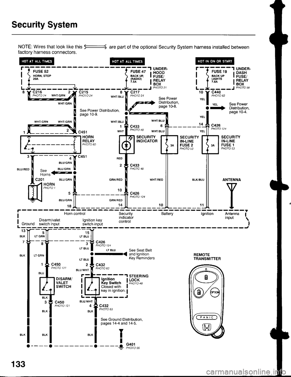
Security System
NOTE: Wires that look like this --::= are part of the optional Security System harness installed betlveen
factory harness connectors.
!-l-'*;;--
-----f.-u'?;l
HBB'J' !--T-'u-"-"-13X3"'*-| ) Ho-BN.srop ) B..l\-cj^qp I FUSE/ | ) Flg!!!p I FusE,| 1."^ | lTl"'", I RELAY I a ;'lx'" I RELAY| {--------------- l'* | Box I l -^ lBox
LJ--------.J4---------9----JP4oto21 L-Ja----JPHoro,3"\W27**^ -"hlT'jZn8:,*[:*ift :.1::t*'
seepowerpage 1o-8. a+ Distributjon,See Power Dislribulion. rZ)z----- I page 104.page 10-9.
''"' "t' 1.*"
*', "r:l-
- - - - - -,C **
, f]3,"0u, "1,f ";"3" *",J"11-------;'ff ;;;"
[F=]F;"#,.. kfl
t"ffBr+T'
EilHr{" E
mli
"."".:X-:-S]""'
"T['*-
ll ll
ffi'-"*FL_____r*F_*l
l^y^
c4s1 wnr I t"o'o 'o tn"r ".u | | ".. | | *n' ' '
i Horn control Security Battery lgnition Antenna Ia Horn control Security Battery lgnilion Antenna I
I Drsarm/varet rq indicator 'nPut \
: Ground switch input r.JllXi'lJ;,L control I! Ground switch input s'ivitcn inprlt IL------; ------Jtoy--T|f- -----,;]1
BrK ll rrGRNll LrBLU ll7 Yi- -;-lt- - - - - - -;-:t c426
"-l ,"":l :::lb.i[ri?n'a'fl:. r..rn?.,n| 'eru I Kev Reminders rRANsMlrrER
r
c4so z:L cqgz
:l-il*
",, I
ttu' . *'*'i'f, F;l'o"
rh d.,til i;-fr H{jfJ. I i{",;::*
Ed'"""" LliCir'l':i
":it*t*'
"t--,i[;""
I See Ground Distributron.I pages 14-4 and 14 5.
-.1
I
I
"..1
133
G401
Page 1558 of 1681
lnterlock System
- How the Circuit Works
Key Interlock
Battery voltage is supplied at all times through f use
33 to the key interlock switch. When the key is in
the ignition, battery voltage is supplied to the key
intedock solenoid and the key interlock circuit in the
interlock control unit. When the A/T gear position
switch is in PABK, ground is provided to the key
interlock circuit. This removes ground from the
interlock solenoid, the solenoid is deenergized, and
the key can be removed from the ignition.
Shift Position Interlock
Battery voltage is supplied at all times lrom fuse 52
to the brake switch. With the ignition in ON (ll) or
START (lll), battery voltage is supplied through luse
25 to the shift lock solenoid. When you push the
brake pedal, battery voltage is applied through the
GRN/VVHT wire to the transmission ('98-�99 models)
or powertrain ('00 model) control module (TCM or
PCM). lf, at the same time, you do not push the
accelerator pedal, a low voltage signal is sent
through the RED/BLK wire to the TCM or PCM. The
TCM or PCM then applies voltage through the
WHT/RED wire to the shift lock circuit in the
interlock control unit. lf the A,/T gear position switch
is in the PARK position, the shift lock circuit
provides ground to the shift lock solenoid. The
solenoid is then energized, and the shift lever can
be moved from the PARK Dosition.
Refer to the Service Manual (Section 23, Electrical)
for specific tests or troubleshooting procedures.
138-2
Page 1561 of 1681
Power Mirrors
- How the Gircuit Works
The two outside mirrors are controlled by the power
minor switch. Each mirror has two reversible
motors: one motor moves the mirror uo and down
and the other motor moves the mirror left and right.
The oower mirror switch contains three switches lo
control mirror direction, and two switches to select
the left or right mirror. With the ignition in ON (ll),
battery voltage is supplied to the power mirror
switch. The mirror selector switch directs voltage
from two of the direction switches to either the left
or the right minor. Each direction switch is used for
more than one function.
Mirror Up Operation
With the power mirror switch in the up position,
switch 1 is moved to the A oosition. Switch 1
applies battery voltage to both the left and right
power mirror up/down motors. lf the mirror selector
switch is in the left position, the left up/down motor
is grounded through the mirror selector switch and
switch 2 in the B position to G501 (Sedan) or G502
(Hatchback). lf the right mirror up/down motor is
selected il is also grounded through switch 2 in the
B position.
Mirror Down Operation
With the power mirror switch in the down position,
switches 2 and 3 are moved to the A position.
Switch 2 applies battery voltage to the left or right
power mirror up/down motor as determined by the
mirror selector switch. The selected mirror motor is
grounded through switch I in the B position to G501
(Sedan) or G502 (Hatchback). When switch 2 is
moved to position A, it also applies battery voltage
to the selected mirror lefyright motor. With switch 3
in the A position, battery voltage is supplied to both
sides of the leruright motor so it does not move.
Mirror Left Operation
With the power mirror switch in the left position,
switches 1 and ? ate moved to the A oosition.
Switch 2 applies battery voltage to the left or right
power mirror lefvright motor as determined by the
mirror selector switch. The selected mirror motor is
grounded through switch 3 in the B position to G501
(Sedan) or G502 (Hatchback). When switch 2 is
moved to position A, it also applies battery voltage
to the selected mirror up/down molor. With switch 1
in the A position, battery voltage is supplied to both
sides of the uD/down motor so it does not move.
Mirror Right Operation
With the power mirror switch in the right position,
switch 3 is moved to the A position. Switch 3
applies battery voltage through the mirror selector
switch to the left or right lefvright motor. The
motor is grounded through the mirror selector
switch and switch 2 in the B oosition to G501
(Sedan) or G502 (Hatchback).
Refer to the Service Manual (Section 23, Electrical)
for specific tests or troubleshooting procedures.
141-2
Page 1562 of 1681
Stereo Sound System
UNDER-HOOD.I UNDER-DASH
I FUSE/RELAYI
I
I
-T',
?j-v,-
:I
rl
I
I
I
8
WH'/BLU
FUSE 28BAO|()roa
L_L____l_J
FUSE 47FUSE/RELAYBOXaacx ug{aao|o)
c217
c551 oPT|ONPHOTA 58 CONNECTOR19 t, C551
See PgwerDistribution,10-8.
10(RS e)
c505
Sodan
It
Itc
(NotUsed)
6 l,-"."'c"" I
Harcnoact j
T_
i
tSee
AntennaCRY/ALK
I
csos
c506
8RN/BLK
I
c452
c401
FRONTPASSEN-GER'SDOORSPEAKER
Battery(memory)
Powerantennaconrol
150
Page 1565 of 1681
Clock
I
I
8(RS 7)
WHT/BLU
UNDER-HOODruse lz I FUSE/RELAY
lragr-lle I Pg^I^ ^
{f*'o, a PHafo 21
c2'17
aaaQ
c452
aaaa)'
"-,,[r*"
nnT,i"".'-.)
I
Y
See PowarDistribution,page 10-5.
r--I------1 UNDER-DASHI f FUSE2S I FUSE,RELAY
a J y5t* a"';L,,
| | See Power l
r f+ ?:"i:q*t:"' IL--9,-.-=:-:J10 Y C551
8
WHT/BLU
WHT/BLU
See PowerDistribution,page 10-8.
WHT/BLU
See PowerDistribution,page 10-8.
See Dash andConsole Lights
T
I
"ao,"a* f
--J"*'
CLOCKBattery(memoryJlgnitionDimminginput
Ground
1 Y C561
',54
Page 1596 of 1681
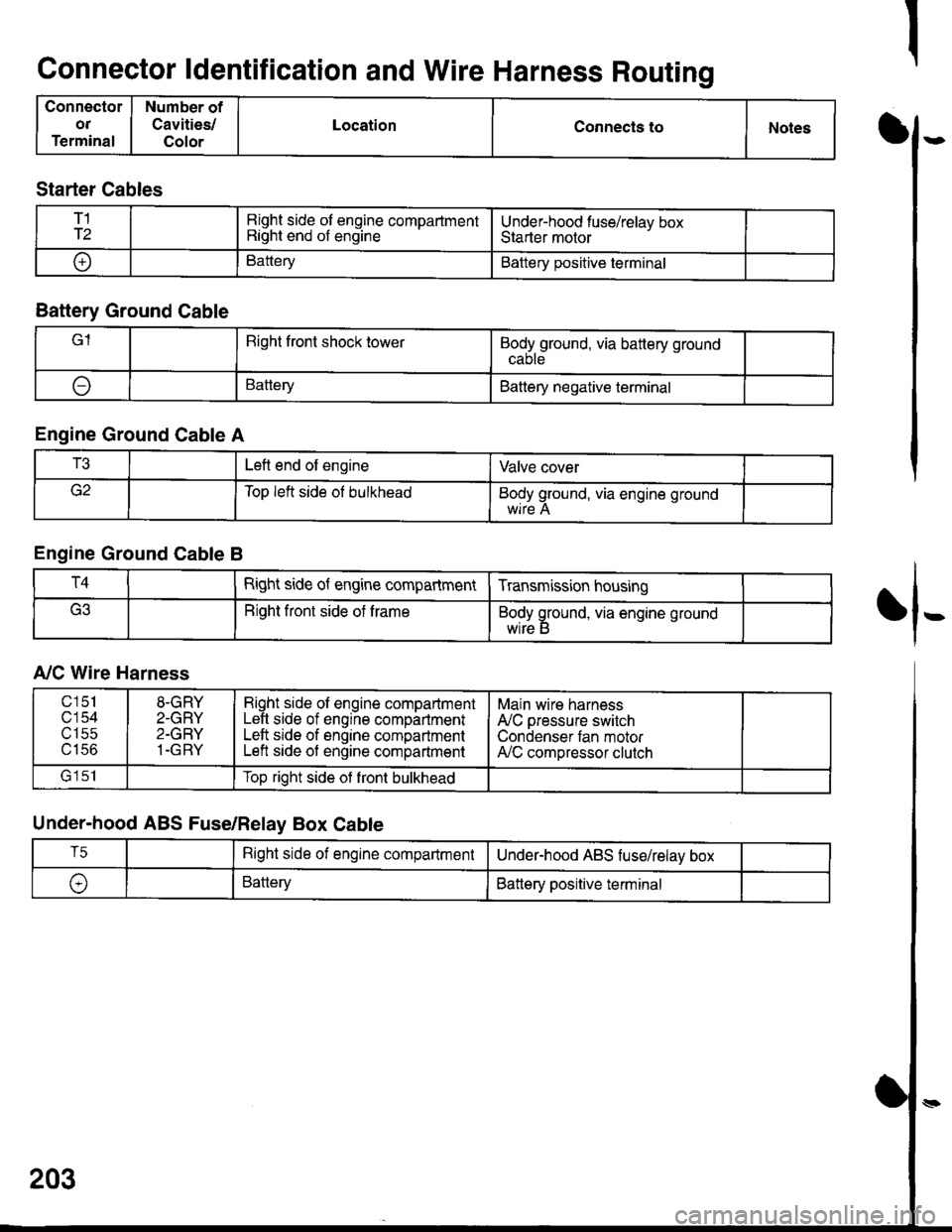
Connector ldentification and Wire Harness Routing
Connector
OT
Terminal
Number of
Cavities/
Color
LocationConnecls toNotesI
fl-
Starter Cables
T1
T2Right side of engine compartmentRight end of engineUnder-hood fuse/relav boxStarter motor
oBatteryBattery positive terminal
Battery Ground Cable
lRight front shock towerBodyground, via battery ground
ABatteryBattery negative terminal
Engine Ground Cable A
T3Left end of engineValve cover
Top left side ol bulkheadBody ground, via engine ground
Engine Ground Cable B
T4Right side of engine compartmentTransmission housing
Right front side of trameBody ground, via engine ground
wrre b
A,/C Wire Harness
Under-hood ABS Fuse/Relay Box Cable
203
c151
c'154utSc
u tco
8-GRY
2-GRY
2-GRY
1-GRY
Right side ol engine compartmentLeft side of engine compartmentLeft srde of engine compartmentLeft side of engine compartment
Main wire harness
A'lC pressure switch
Condenser tan motorA,/C compressor clutch
lrlclTop right side ot front bulkhead
T5Right side of engine compartmentUnderhood ABS fuse/relav box
\,BatteryBattery positive terminal
Page 1597 of 1681
)-
)-
UNDER-HOOD ABSFUSE/RELAY BOX CABLE
BATTERY GROUNDCABLE
ENGINE GROUNDCABLE B
A/C WIRE HARNESS
T3
ENGINE GROUNDCABLE A
)t
203-1