Page 1408 of 1681

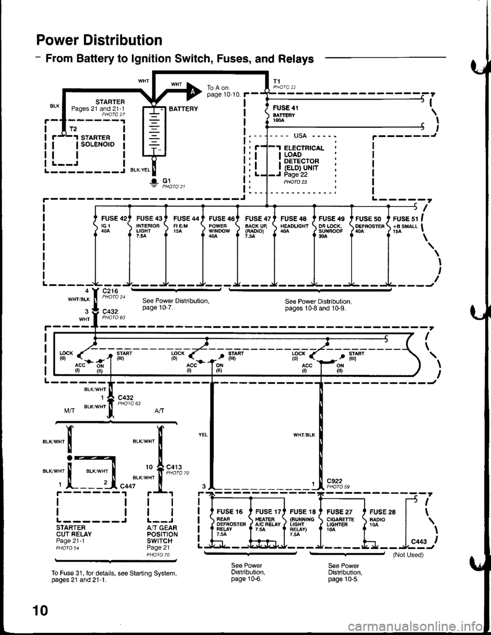
Power Distribution
- From Battery to lgnition Switch, Fuses, and Relays
T1
STARTERPages 21 and 21-1PHOfa 27
FUSE 42tGt
c216
STARTER
| | soLENorD
tlL--J I--------J BLKTYEL
I- G1
I
ILI (ELD} UNITI Page 22
I LOAD: DETECTOR
ELECTNICAL
PHOTO 23
BATTEFYFUSE 4tBATTEAYtmA
,
I
I
L-----?
I
FUSE 43IMTEFIOBLIGHT7.5A
FUSE 44FI E/M15A
FUSE 46FUSE 47AACK UE(RAOTO)7.la
FUSE 48NEADLIGHTFUSE 49DA LOCK,su{BooF304
FUSE 50OEFFOSTERruse sr I+B suaLl I
\
I
I
WH'/BLKSee Power Distribution,pages 1Gg and 10-9.c432
I
\
BLK/WHT'I
Mff BLK/wHr
c432
".__",x'
c922
FUSE I8(aurxf{GIIGHTRE!AY)7.54
FUSE 27C|GAAETTELG}T'ER104
FUSE 28RADIO
f.--
r(
l*,)
See PowerDistribution,page 10-6.
See PowerDistribution,page |0-5.
--':'[E
I
IL------STARTERCUT RELAYPage 21 -1
To Fuse 31, tor details, see Starting System,pages 21 and 21-1.
See Power Distribution,page 10'7.
lff- (".-
r-r
tili*lff* r
acc{r)
FUSE 16AEAAOEFFOSTEAFELAY7.54
If"a*t "t I
i
'o f,""f#
"ooi'*
*"'
i.t r+t
ttl
trlJ L--JA/T GEARPOStTtONswtTcHPage 21PHA|A 7A
10
(Not Used)
Page 1419 of 1681
TRANSMISSION
I
I
T4
PGM-FIMAIN RELAYPage 23 ('98-'99)or 24 ( 00)
tl
tlL-J
* : '98-'99 Models
i---------\L---------J(- 10) r-- -;-;.11, (c408.)(- 23)10
'98- 99.. GS.R' l/odel
inrrarerrn i
I
I
.-- GS-R. TYPE.R
VEHICLESPEEDSENSORRADIATOBFAN SWITCH
and 63 2
tl
tlL-Jcl08
(vss)Page
PHATO 6IIITJ
I
I
33
I
I
c3o1 ;
10
Ground Distribution
NOTE: Wires shown without color codes are black.
VALVECOVER
I
I
- G1, G2, G3, and G101
I
I
T3
BATTERYPage 10
r-'r
tl
ll'n'
I
I
I
I
I*-*rl
I
I
I
I
! F,to,o^_l1io,o,o *
14
Page 1431 of 1681
- Automatic Transmission
NorE: For cars equipped with optional security system, see security system, page 13g-3 tor startrngsystem circuit schematic.
Starting System
c216
FUSE 42tGt
UNDER-HOODFUSE/RELAYBOX
See PowerDistributian,page 10.
liu.) 3:i:it1-i*!
i!'''{=o1ili"' i i!i (=r.f(',ii i I
!i rfi,l.l i I
!L----J------j Ir'---BLK;HrT---------=---r
".o"rnrfi F,i% u.,
'to A co' s
3 V C432
BLr!,Y/Ht ll PHoro 70
04-;' s
\z
1l
t:
t,
t;
t:
t:
t,N^/.
A,/TGEARPOSITIONswtTcH
ALKFEO
't1
EIIVRED
BLKFED
t2
I BLK/RED
'4
BLI(FED
178LK/BEO'I
BLKII/HT
FUSE 41BATTEiYr00A
To
c413
See PowetDistribution,page 10.--i--;-JT1
BATTERY
c444
{Not Used)
All exceplUSA FS
c301
c126PHOTO 36c4404 ^, PHO|O 62
STARTERrrF-----1
! i rur..r !| snnrea sour- || 1 '* |
! Ir-'Lg"' i
llttl
llr | |
llL-J Ir I INTEGRATEo I! I CONTROL I
I luNrr I
tIbEt:_J
UNDER-DASHFUSE/RELAYBOX
WHT/ALK
--- usA ---
.I ELECTBTCALI LOADI DETECTOR
i (ELD) uNrr. PHOIO 23I
21
lGlSee PGM-FI, paqe 23.1('98.'99) or 24-1I OO).
Page 1432 of 1681
- Manual Transmission
NOTE: For cars equipped with optional security system, see security system, page 133-3 for starting
system circuit schematic.
c432
FUSE 42tGl
c216
r
I
I
I
I
I
I
I
I
I
]
UNDER.HOODFUSE/RELAYBOX
ELECTRICALloAoDETECTOR(ELD) UN|T
START(10
c432
.Joil0t)
BLKWHT
1
BLK/IVHT
(o) ,t-,>
0)
,i
I
l
Ia
I
I
I
I
BLKA''HT II--2 A cqqz
"4
".u,".0^ tr-
- -----
t I coee
Hifr*',;*-"J
":-r
"*'
: See Ground
I Rl"i:b,*?"
""1;
' PHOIO 56
STARTERCUTRELAY
See PowerDistribution,page 10.
T1PHO|Q22
BLK/REO
BLK/BEO
a=z
lt
lta c444
Used)
c444All exceptUSA RS
See PolYerDistribution,page 10.
BLK/REO
1
ALK/WHI
c301
c126PHOTA 36c440
BATTERYSTARTERrrF-----1
! { H:.i,r'",""^. I
li ?.ea I
!l';Lg" i
|r | |
ill l lllL-J I! I INTEGRATED ]| | coNrRoL I
Ll'l,l't--i
UNDER.DASHFUSE/RELAYBOX
See PGM'Fl, page 23-l('98-99) or 24-1 ('00).
t2 A Clos
-a- G1
21-1
Page 1433 of 1681
Charging System
1;+ Sl"Jlit*"'
BATTERY
lGl
Ses Power
* = 98- 99 f,rodels
ALTERNATOR
lgnitioninput
Load
Ground oulpur
22
Page 1435 of 1681
PGM-Fl ('98-'99 Models)
UNDER.OASHFUSE/RELAYBOX
- -6J C446
YEUELK I
YEUBLK
13YEL/BLK
12YEL/BLK
c301
c127
YELlBLK
See GroundDistribution,page 14.
V
I
,-J
G101
10za ^--- 11
c10 M4 A11 ,aL4 A3 A2 41 '(vBU) (lcp2) (GFr) (rNJ1) 0NJ2) (rNJ3) (rNJ4) !Battery Power Power e \oic[-rjp ;"ira input Fuel injector controt \
L
o
23
Page 1452 of 1681
- How the Circuit Works
With the ignition switch in ON (ll) or START (lll),
battery voltage is supplied through fuse 15 and the
BLK//EL wire to the vehicle speed sensor (VSS).
The sensor is grounded by the BLK wire to G101.
The speedometer and other control units in the
circuit supply about 5 volts to the ORN wire. The
vehicle speed sensor (VSS) intermittently grounds
the ORN wire which generates a pulsed signal in it.
The number of pulses per minute increases/
decreases with the speed of the car
Refer to the Service Manual (Section 23, Electrical)
for specific tests or troubleshooting procedures.
33-1
Page 1458 of 1681

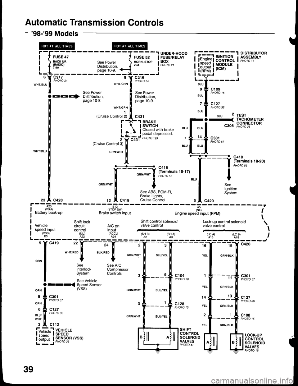
Automatic Transmission Controls
- '98-'99 Models
-I,;;;
EACK Ue
-l'::-
FUSE 52NOFN, STOP204
UNDER-HOODFUSE/RELAYBOXSee PowerDistribution,page 10-9.
isToP s
v)Brake switch input
8c217
aa+
I Y C216ll PHaTa 24wHrcFN iSee Power ! See power
Distribution. I Distributron,page 1G8. I OuO" tO-S.
""t o:"
I(Cruise Contror 2) I C431
r rN-.t BRAKE
I | swrrcH
L q-: j ;,,?i,i?'Y,i *i,i:5"
2Ycqst "u'o '*
(Cfuise Control3t
IGFNvHT
Il'+^..6'f- - - --_- -
:f irlliin"r" r s-r zy
I
GFN wHr I 'r'oro'o
cnrwnr I t
i 8:i^i?i,i":"tZ I Cqtg Cruise C-ontrol
] fii1f,,",.,..,,
Y
SeelgnitionSystem
l---83ivBU)Battery back-up
812',
I(nE)Engine speed input (FPM)
Shitt tock Shift controlsotenoid Look_up coo.trol solenoid \VehiCle Cifcuit A,/C on valve control valve controlspeed-input control ilp"ui' ,-'H...,.,,,,..r \"&. ,j5? ,X%""r' ,"lru' rsHAr 'lgl' ,l:"u) IL _ iq - _ _ _ _ E?_ _ _ _ g'_ _ _ _ 5i _ _ _E: _ _ _ _ _ !t- _ _ _:&: _ _ _ - _tu
f
"0"
-",:: [-;"f
-
"- "T-. -T----=T--_5
"-'
*"
I p*t ^", 3rl**.,*""
-"'
il
-'-..
|
-.
|
"* *^
|
| $:'"::""
33n:Ji.'*' .
|___{ r*,," ,
f----,{ r*:,,
.ri-,-:-
ssc"ds"n'o.
"""**
|
*,"*! ""1 o"n"'* |
*f n';,, . L__J
" [--:'] ,';7..
-.: t "';%,.
-i,.!..,,, ""^"-l'-;;{t**' j:l#r-
iyi,:?n$i,:*""" ffiBB'rI"o."L*.."'.i-ii.*'ji"[!si"""' ,,_r_,"'liiif+:rm U;1f$+f,
:[ilrF""#**F.tr
39