1998 HONDA INTEGRA service
[x] Cancel search: servicePage 1395 of 1681
How To Use This Manual
Test Equipment
lf, in addition, you need to know exactly how
much resistance there is between two ooints.
use a digital volVohmmeter (DVOM).
In the "oHMS" range, the DVOM will show
resistance between two points along a circuit.
Low resistance means good continuity.
Diodes and solid-state devices in a circuit can
make a DVOM give a false reading. To check
a reading, reverse the leads, and take a
second reading. lf the readings differ, the
component is affecting the measurement.
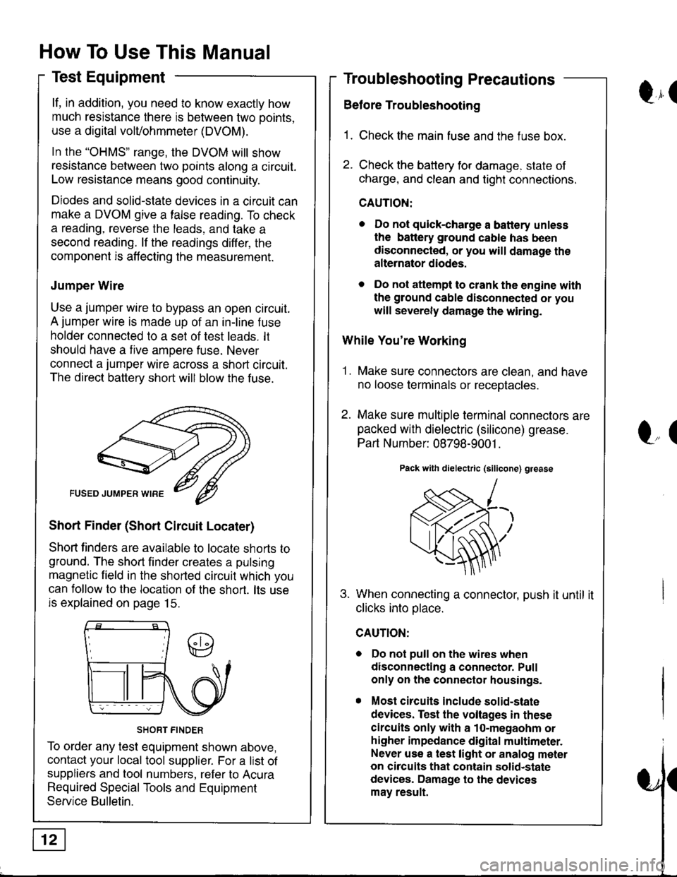
Jumper Wire
Use a jumper wire to bypass an open circuit.
A jumper wire is made up of an in-line f use
holder connected to a set of test leads. lt
should have a tive ampere fuse. Never
connect a jumper wire across a short circuit.
The direct battery short will blow the fuse.
Short Finder (Short Circuit Locater)
Shoft linders are available to locate shorts to
ground. The short finder creates a pulsing
magnetic field in the shorted circuit which you
can follow to the location of the short. lts use
is explained on page 15.
SHORT FINDER
To order any test equipment shown above,
contact your local tool supplier. For a list of
suppliers and tool numbers, refer to Acura
Required Special Tools and Equipment
Service Bulletin.
Troubleshooting Precautions
Before Troubleshooting
1. Check the main fuse and the fuse box.
2. Check the battery for damage. state of
charge, and clean and tight connections.
CAUTION:
. Do not quick-charge a battery unless
the battery ground cable has been
disconnected, or you will damage the
alternator diodes.
. Do not attempt to crank the engine with
the ground cable disconnected or you
will severely damage the wiring.
While You're Working
1. Make sure connectors are clean, and have
no loose terminals or receotacles.
2. Make sure multiple terminal connectors are
packed with dielectric (silicone) grease.
Part Number: 08798-9001 .
Pack with dielectric (silicone) grease
When connecting a connector, push it until it
clicks into olace.
Do not pull on the wires when
disconnecting a connector. Pull
only on the connector housings.
Most circuits include solid-state
devices. Test the voltages in these
circuits only with a 1o-megaohm or
higher impedance digital multimeter.
Never use a test light or analog meter
on circuits that contain solid-state
devices. Damage to the devices
may result.
Qr(
l"(
Page 1406 of 1681
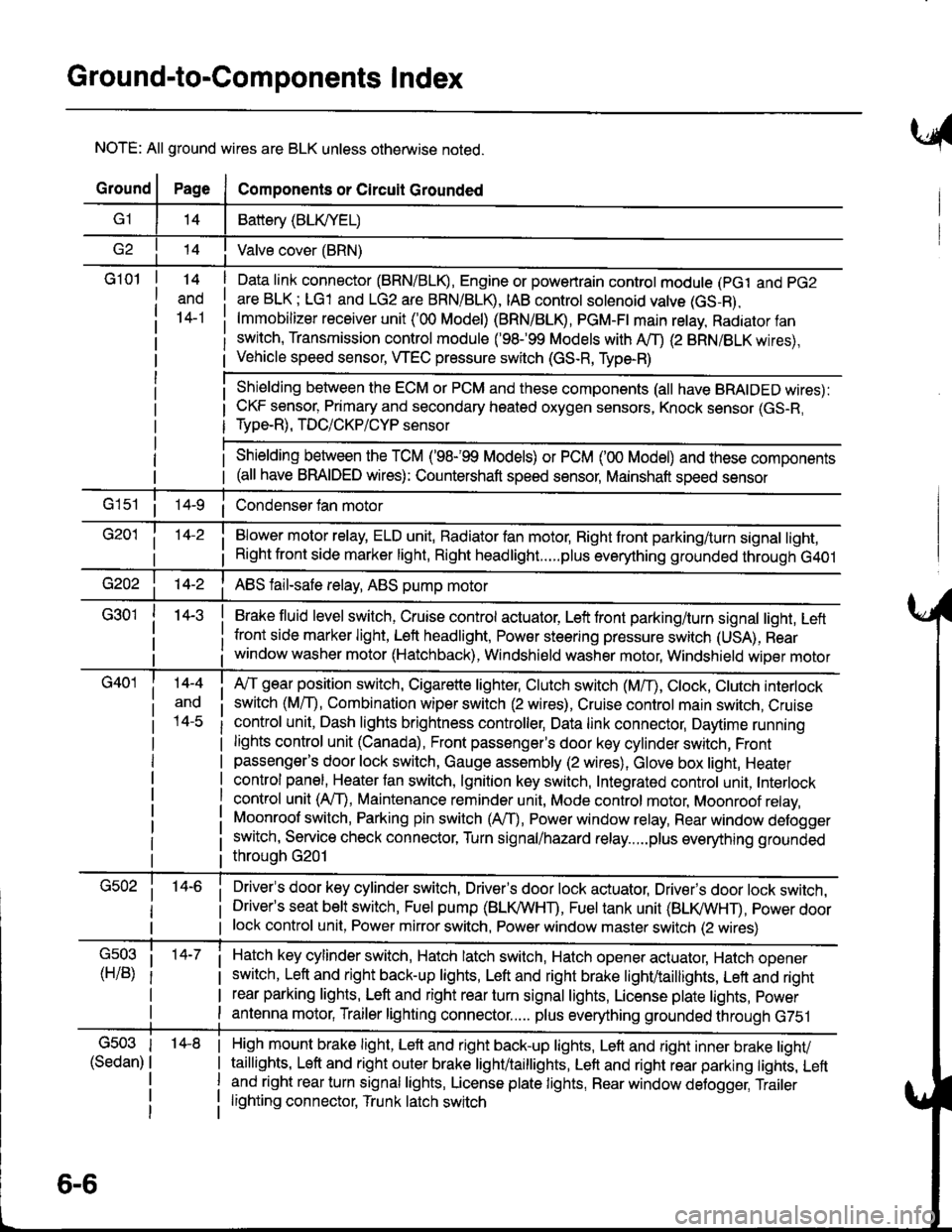
Ground-to-Components I ndex
NOTE: All ground wires are BLK unless otherwise noted.
GroundPageComponents or Circuit Grounded
Battery (BLIVYEL)
--t'I Valve cover (BRN)
G101t.+
and
14-1
Daia link connector (BRN/BLK), Engine or powertrain controt module (pct and pG2
are BLK; LG1 and LG2 are BRN/BLR, IAB controt solenoid valve (GS-B),
lmmobilizer receiver unit ('00 Model) (BRN/BLR, PGM-Ft main retay, Radiator fan
switch, Transmission control module ('98.�99 Models with MD (2 BRN/BLK wires),
Vehicle speed sensor, WEC pressure switch (GS-R, Type-R)
Shielding between the ECM or PCM and these components (all have BRAIDED wires):
CKF sensor, Primary and secondary heated oxygen sensors, Knock sensor (GS-R,
Type-R), TDC/CKP/CYP sensor
Shielding between the TCM ('98-'99 Models) or PCM ('00 Model) and these components(all have BRAIDED wires): Countershaft speed sensor, Mainshaft speed sensor
G1s1 ii Condenser fan motor
Brake fluid level switch, Cruise control actuator, Left front parking/turn signal light, Left
front side marker light, Left headlight, Power steering pressure switch (USA), Rear
window washer motor (Hatchback), Windshield washer motor, Windshield wiper motor
14-3
Blower motor relay, ELD unit, Badiator fan motor, Right front parking/turn signal light,
Right front side marker light, Right headlight.....plus everything grounded through G401
ABS fail-safe relay, ABS pump motor
G40114-4
ano
l4-c
A,/T gear position switch, Cigarette lighter, Clutch switch (M,/T), Ctock, Ctutch interlock
switch (MfD, Combination wiper switch (2 wires), Cruise control main switch, Cruise
control unit, Dash lights brightness controller, Data link connector, Daytime running
lights control unit (Canada), Front passenger's door key cylinder switch, Frontpassenger's door lock switch, Gauge assembly (2 wires), Glove box light, Heater
control panel, Heater tan switch, lgnition key switch, Integrated control unit, Interlock
control unit (AfI), Maintenance reminder unit, Mode control motor, Moonroof relay,
Moonroof switch, Parking pin switch (AfD, Power window relay, Rear window defogger
switch, Service check connector, Turn signal/hazard relay.....plus everything grounded
throuoh G201
Driver's door key cylinder switch, Driver's door lock actuator, Drivels door lock switch,Driver's seat belt switch, Fuel pump (BLI(/WHT), Fuel tank unit (BLI(/WHT), power doorlock control unit, Power mirror switch, Power window master switch (2 wires)
Hatch key cylinder switch, Hatch latch switch, Hatch opener actuator, Hatch ooener
switch, Left and right back-up lights, Left and right brake light/taillights, Lett and right
rear parking lights, Left and right rear turn signal lights, License plate lights, power
antenna motor, Trailer lighting connector..... plus everything grounded through G751
6-6
'14-8G503
(Sedan)
High mount brake light, Left and right back-up lights, Lett and right inner brake tighv
taillights, Left and right outer brake light/taittights, Left and right rear parking tights, Leftand right rear turn signal lights, License plate lights, Rear window detogger, Trailer
lighting connector, Trunk latch switch
Page 1423 of 1681
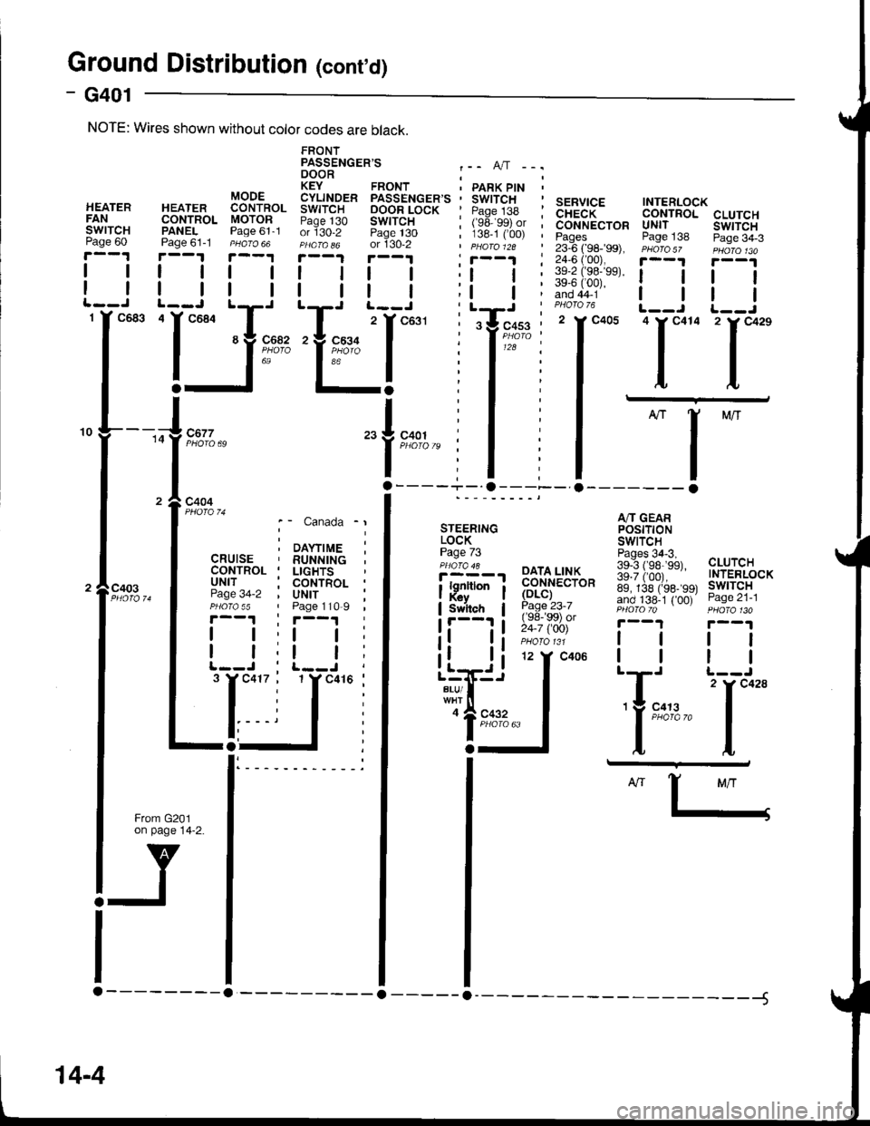
Ground Distributior (cont'd)
- G401
CLUTCHswtTcHPage 34-3
tl
tl
'l**
A/T GEARPOStTTONSWITCH
139""i#;3a, cLUrcH
ig.ii,oor.--" TNTERLOCK
89, 138 (rss- 99t lwlTcHand 138-1 { 00) Page zl-lPHO|OTo PHOfa 130
r--1 r--1
lttl
ttlll-J t--J
| 2 rc428'Y 9:t:,2." I
ttI,L
SERVICE INTERLOCKCHECK CONTROLCONNECTOR UNITPages Page 13823-6 ( 98-�99), PHoro5z24,6 ('00), i--t
iifiii;"' ! !PHOTO 76 L__J'I*- 'l*"
I -
I
-l
ll- o------- o
FRONTPASSENGER'S .-. A,/T -..DOOR ;KEY FRONT ' PARK PtN 'CYLINDER PASSENGER'S ' SWITCHSWITCH OOOR LOCK ' Paqe 138 :Paqe 130 SWITCH I (ge ggt or ior130-2 Page t30 ; 138-1 C00) ,PHafa o6 or 130-2 | pHaro 12a
!.--.! r--1 , r--1 :I | | | ;l | :
| | I | ;t | ;tT' t^-.--i^- , LrJ
"I ^^^-
z
l
t'or' : tY'"*u"" :'Yk91i t ' I'zi :a';"'" I : I
I I :lErl
"1i,.
| .
NOTE: Wires shown without color codes are black.
c403
STEERINGLOCKPage 73'i!Y-', PAIA,LT$
| . i ;;":,;i;
;p,'nron i ffi."ro*Switch I Page 23-7
!'---'' i !i:; iSii'
);
DAYTIMERUNNINGLIGHTSCONTROLUNITPage 110-9
tl
tl
't Y c41(
Canada
\YTIME
Page
I
I12 Y C406
c41
o
a
Llrri.i
i'#!"..,'lgl::""
14-4
Page 1429 of 1681
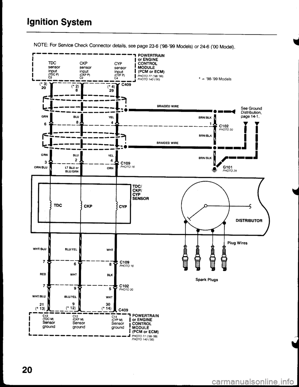
lgnition System
INorE: For service check connector details, see page 23-6 ('98-99 Models) or 2zl-6 ('00 Model).
POWERTRAINI a oielcirs '-"
rDc cKp cyp i coNTRoLsensor sensor sensor ! MODULEinout inout intu,t | /PCM.ri! input input inDut | (pCM or ECM)I g"oc et !cj
u"n,"." ! ----t
:jl--Jt---r-4,*"
"""*-Lf;
'':[:-==1-I=-==g=,-
u-{:::::L:::::+=i--- ""^".:-I'
.rr. s::3-.-:
;f:===-l_=* -=-f,*,,'fT
L-f--====E=--==i.l ""'"'"*'"'
=="=-'!---.!
I
-A 2r .|--___-OFNi 8LU II LT 8LU orI BLU/GRN
----o A c';;? F;o''","i:- F,to,l.,
Plug Wires
- - - -"-'lg- - - - - -^11 ct og
Spark Plugs
' Y-----rV-
- - - - ;V t#'",.
WHT.BLU ll BLU,"YEL I wHT
,. ?1, L--rrl:-,!-__,. ?Ll.oo,
cr3 c12 - - -.,,--a POWERTRATN(Dc Mr rckp M) icrb 6 | or ENGINEuensor Sensor Sensor i coNTRoLground ground grouno !laODuLi
20
Page 1441 of 1681
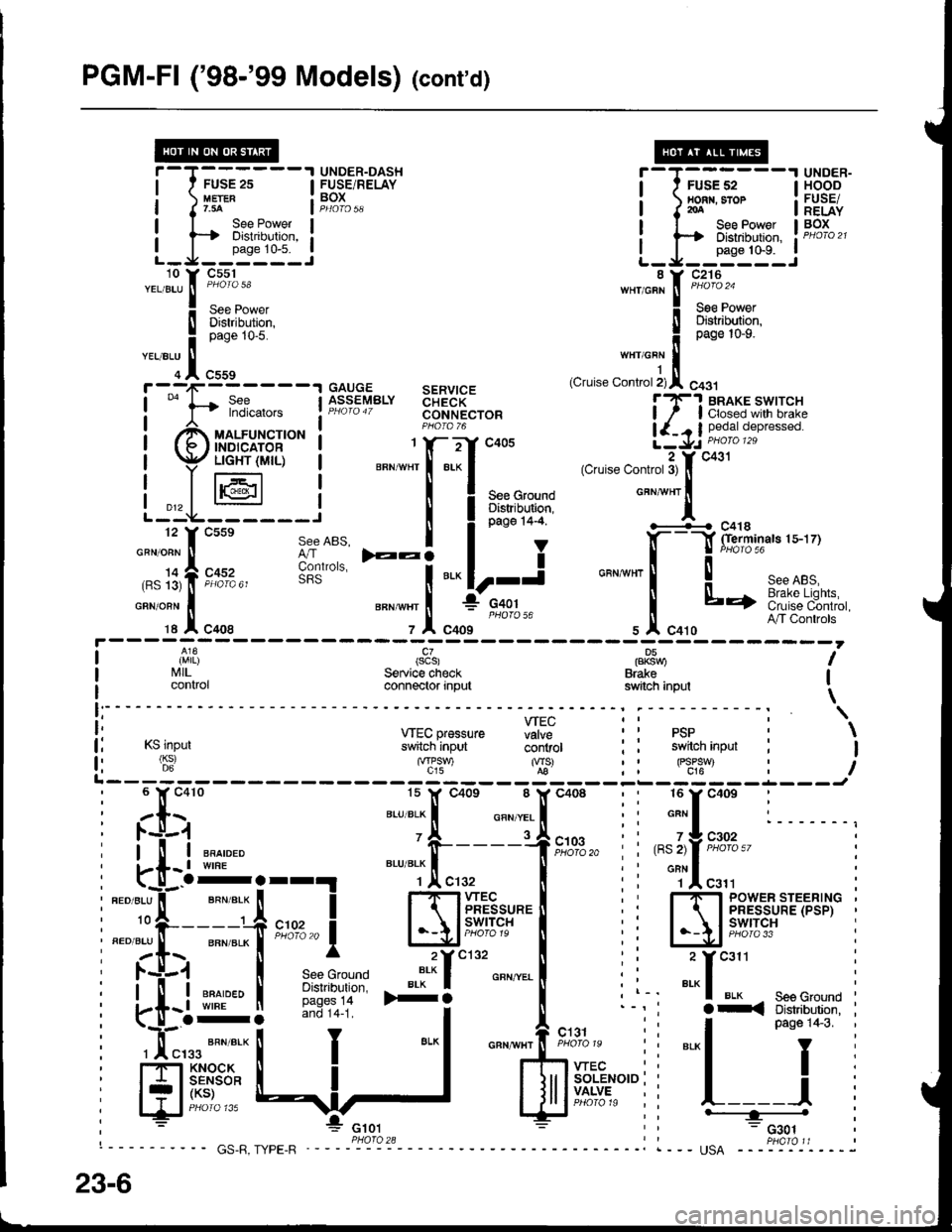
PGM-Fl ('98-'99 Models) (cont'd)
FUSE 2s
See PowerDistribution,
L_J__':n1:'_.:
i-T;;,;,---l HSBE'I nonr. sror : FUSE/I J roA I RELAYI I See Power I BOx
i ts Distribution, ! PHoro2t
L_J__0"n" to'n_..i
UNDER-DASH T-T------'I UNDER-FUSE/RELAY I ' FUSEs2 IHOODtuErER : BOX ! nonn.sror : FUSETr.3A Jp4oro5q I I2oA I RELAY
uauuE sERvtcEASSEMBLY aHidK- lT'! BRAKE swtrcHPHaro4T coNNEcroR ! / I closed wilh brakeP1oro 76 | {_. I pedat depressed.1 Y- -:-'Y .:rnE a \1,. DHOIO 129i 66g"; ilti5Xx+15l'""
I PHoroT6
ll^3j l;i,X|,io'"*".
i ry/,-'Em.dui6 | *";Xf-".'{'*',.."".*,'",-A*f.i.";"'"
Lt*F,--;J^,,
I i**''i
";\&**"**
| li'l|l (scs) pP8nu I
I I'illL. Service check Brake Ii control connector input switch inpul \
i: wEcpressure fiff ii psp : \
lj rslnpur s*[cninput- ii'iiror : i switch inpur : I
fi (6:) '"f'?-) %-' : : FJ:*t : iL------- t-L---J
;tx;
"-'TJ.!.
"oo,
: :[:"': l. -u-.1
i[uE,
i
*"T,!. enroLxl
' -i-----1
i
".''"]rf
_ en*err I
i fi:i
-'-- !
i 'T""t """'"'- !
ilrff:;iJ:rl *:f
See ABS, I
6lt"uo,", F:i
ffi; :i
*.1
I
i ll-i ""^,"." 'fr----1f,il0,3,,
i i ,"l,fF'%%"' i, i-[- t wrne BLU BLK f ll ; ' onN I
i"..*t-T;i;;i ffiff'rul.'l ii Ej'ir1'pi='Et'x'i
I la$ I .*^*"'-" ".*'f ""'^..-.
! i i _:f
*" :
: i-[l ffir* I iii:!:i* >+i
o"n""l
i l-' "'"1 u'* - seeGround I
i
-o-: --1i i l^_^-
'1:
i-<3:"J:qT3"'i
i Hf'.!$*
ll
J
I
lJrlffi"r"",
: l__ j
, : *"* E ;; ---="*L-l
"*fiix+*,"i
i
""[
23-6
Page 1449 of 1681
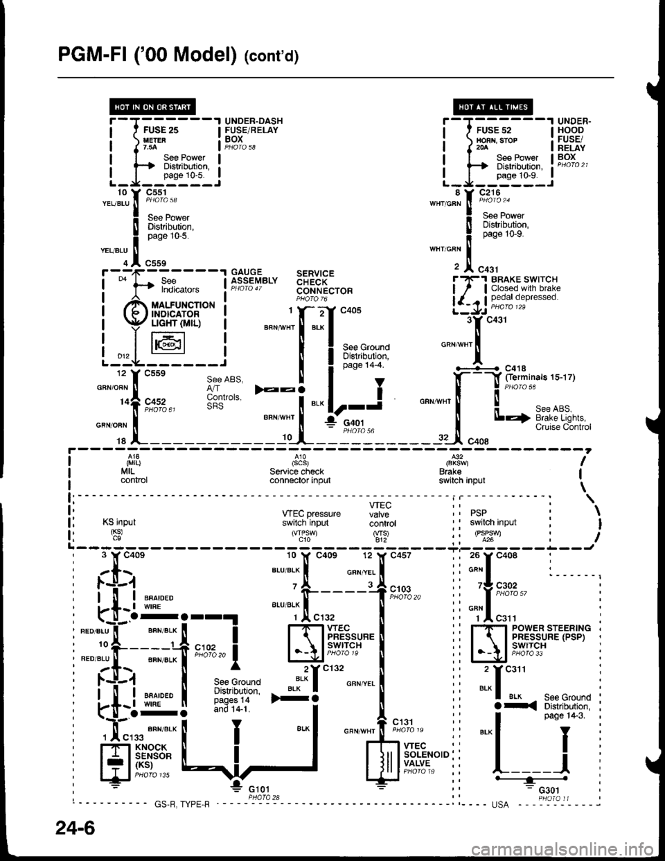
PGM-FI ('00 Model) lcont'd)
f ---,1-------1 GAITGE SERVICE
!
""
l-t fl?i*." lfr:?"'Y"'" 33FR[",o"I
| ""^,.,^
""r,o"t" t F;J$"
i Br,ffi*
-""'Ti"::"'""
'
F fl::"",.,, !f":?sy"'" $FR["r"" i7.l S[t5',"',1flJ,:1"
,ff uo.rrn"t'o* ! PHoro-6
!-r -/ ffi ore'"*"o
(f/ffirir,r$- I """-"11-"J** 3yc431
| p$tr6l:,- i *".;f:.:f
"oou ..-.t'';;;;" "
l-.L-@---i I Iar'u+t
'""*"'l
12 f csse see ABS. I I o"o" t+-+ '-+---{ c41s
"-"lt;;;"
t;dil
-:i
"."|r-i "".*[--f:il-.
iL_1
SeeABS. I t , .l(- -l fierminals 1s-17)
3o'.,", E:i
"." lr-j o"n,nn, ! J
"o'"'ur""or.
______-.f _t-_il":______rJ"oo,'*Bi""i'""*#i;
I ,i,1|}
I MrL.
I connor
(scs)Service checkconnector input
l€2
Brakeswitch inpul
I
I
\f:----- - - - - - i | - - - - - - - - - - - : \
ii *Ecpressure Hi: ii psp i \
l: Ksinput switch'input coritiot ' I swilch input : I
f l '$' 'T,'J S' ii oll:t : iL------- ------Ji 3 Y c40e 10 lf c40s 12 l( c457 ; ; 26 y c408 :, zls ar-uar-x I o"n.,.. I ii*"I :______,: l.-l-1 'A rJ
; l-'!r-i ""^,"." o-----+t;%," i" 'f ,"#!",,
: kt-l:orr!
"""*.[",.,
| :i "Tl"r" :
I ".o".u"il-' ""n".* [ I 1-1-1wec l� i rf, rsyr:sriF,.rB,]," i
i:."i:t--"# *n,,1 l-\l;tff#"'I ii IA'|5't'f3,i^'''*' i
i zt.\. [ ^ 2Yc132 [ ,' 2 Ycail :
I l.+.1 | see Grouno ':* I o"" ".. I i i ..- I :
i .-tiql i*}:11- *i
I",., ii
"'^f*il{:"{{i$l
i
i *'...#:t I
-"1 """'#*=:
ii
"'-l
pas€1+3
i
i
H** {:,]
'
$ff.':*'"ii l-=i
i
24-6
Page 1452 of 1681
- How the Circuit Works
With the ignition switch in ON (ll) or START (lll),
battery voltage is supplied through fuse 15 and the
BLK//EL wire to the vehicle speed sensor (VSS).
The sensor is grounded by the BLK wire to G101.
The speedometer and other control units in the
circuit supply about 5 volts to the ORN wire. The
vehicle speed sensor (VSS) intermittently grounds
the ORN wire which generates a pulsed signal in it.
The number of pulses per minute increases/
decreases with the speed of the car
Refer to the Service Manual (Section 23, Electrical)
for specific tests or troubleshooting procedures.
33-1
Page 1457 of 1681
Cruise Control (cont'd)
- How the Circuit Works
The cruise control system uses mechanical and
electrical devices to maintain the car's soeed at a
setting selected by the driver.
System Description
The cruise control unit receives command signals
from the cruise control main switch and the cruise
control SevBesume switch. With the ignition switch
in ON (ll) or START (lll), voltage is provided to the
cruise control main switch. When you push the
switch to on, power is provided to the cruise control
unit and the brake switch.
The cruise control unit receives information about
operating conditions from the brake switch, the
ignition control module (lCM), the vehicle speed
sensor (VSS), and the clutch switch (manual
transmission) or the A,/T gear positton switch
(automatic transmission). The cruise control unit
then sends signals to the cruise conirol actuator
which regulates the throttle position to maintain the
selected speed. The control unit compares the
aclual speed of the car to the selected speed. The
control unit then uses the result of that comoarison
to oDen or close the throttle.
The brake switch releases the system's control of
the throttle at the instant you press on the brakepedal. The switch sends a signal to the control unit
by removing power from the normally closed brake
input (GRY wire), and providing power at the
normally open brake input (GRNMHT wire). The
control unit responds by allowing the throttle to
close. The clutch switch or the A/T gear position
switch sends a "disengage" signal to the control unit
that also allows the throttle to close.
The cruise control system will set and automatically
maintain any speed above 25 mph (40 km/h). To set
it, make sure the main switch is on and the switch
indicator is on. Then, after reaching the desired
speed, press the set switch. This sends a "set"
signal to the cruise control unit which, in turn,
controls the cruise control actuator to maintain the
set soeed.
When you push the SET switch and the cruise
control system is on, the "cruise control" ON
indicator lights up.
34-4
You can cancel the cruise control system by
turning the main switch off. This removes power to
the control unit and erases the set sDeed from
memory. lf the system is disengaged temporarily
by the brake switch, or clutch switch, and the car's
speed is still above 25 mph, press the RESUME
switch: the car will automatically return to the
previously set speed.
For gradual acceleration without pressing the
accelerator pedal, push the RESUME switch and
hold it there. This will send an "acceleration" signal
to the control unit. When you release the switch, the
system will be reprogrammed tor the new speed. To
slow the car down, push the SET switch in and hold
it there. This sends a "deceleration" signal to the
control unit, causing the car to coast. When the
desired speed is reached, release the SET switch.
This reprograms the system for the new speed.
Reter to the Service Manual (Section 23, Electrical)
for specific tests or troubleshooting procedures.