Page 1460 of 1681
Automatic Transmission Controls
- '98-'99 Models (cont'd)
YEUatu
-ry
UNDER-DASHFUSE/RELAYBOX
SERVICE CHECK CONNECTOR
1l[----- -i-f c+os
"""t"'
I see
-^
|.EE< ABS,
i-1
Ti:
t':,;"'1...,
*";'1".,,
- sRS
""1
#t*r-^:----- ENGTNE r--:-I TRANSM|SS|ON I rI r*ib rsis, I coNTRoLl r"sb'sr I coNTRoL I i
fl i$yjHlr'!;f#n",!ffiii:' \i- !- G401- PHOTO 56
r)J-1
i*J itTffe.- ir:";-
- - - -
s:I-
- - - -
;;; I HffilEr''". i T r.s:;
- -
II voliage l{ECM) | input
I w,?- | i.o, o,, L :t - - - - - jrfl - - - - - Si
j hfiY:t'
".
i 1-%** i
l_: f, "o'oror c410 4tr-------E[c4ts 17tr' c420 LJ__HSIJ
:ii t Hb ^f'""'* ! "."".* :;;! !
';l "lz*"
-
-[ ;;
"*i*'*i[Try[",".
""."]1,**^ "'""'"!
*u*u''o
ft_ _ _____+___ _ _'lfi g;to,..,. o"n,"J, f t",",,
Page 1464 of 1681
Automatic Transmission Controls
- '00 Model (cont'd)
[---;""'.f
-lc+os 141' c4o8 LJ-:*:IJ
|
:t
, ;:".1
*"",",1 "**-
I
-.11,[t*r'""
I .l ,.,1,","" .J,o*". i
r*ru;l
i.";-
- - -
Is"*
- - - - -
Fsil
- - -
;; I i.l{T'Fil^'- i I ;;
- -
I Ui3"*I voltage Inout
L js!'- - - - - - d": - - - - - 3t - - - - - roql j Hili:
i i-Ti*.*,*,, i F"H*i,'ll-------zrI_------16'rc4os 14tr' c408 LJ_j*::J
:tt, I ".ou.*l I I
r rii ^ r "."-,. r ^""",. r ". ::[ 9#3-
**[
[ [ X"., !r*g+;l"f-----
t
't
l;:,.il*[;,;
""T1",,,""
! ! !i;T-"{_
___-}.[1dnw'"t*il *"*-l "'o*n'l i'I---L-
I I NLi::--::::-:=a-*$$ti
.l_______l ",,, ,l ",,.
'r "*'
I_ITI ENGINE COOLANT
iddirioil I Jr l,.g:tilu;SENSOR lJJal PHora 17
c106
GFN/BLK
SERVICE CHECK CONNECTORPHOIO 76
-"^,:,[
.:
"{
'T[_:'*' "..1
;*liil, lFffi*'" I
c405
BLI
BLK I
I'
See GroundDistribution,pages 14-4and 14-5.
V
I ..
G401
39-6
Page 1468 of 1681
________r 49sI Service I CONTROLBtaxel check DLC : UNIT
r?.:y" t F73il3"11,".o^,park connector inPUVGround Ground Ground Ground input inout outp$(GNo1) {GND2} (GND3) (cNo4) (FAfiK) {scs) (DLc)| (cNo1) (GNDzl (GND3) (cNo4) (FAfiK) {scs) (DLc) !L------- -------J2 y-- ja c7o3 t l- --r-f --4 f - 14 y- - -zil czot'T
T;ui[
----.,-"'{''�*
I |"""'if--- "","-Jt :*
N |
*:[-"-:*ttn"";"'i:
l;l-f*::::ffff'a
:::ffi*
',.-,
'"n"'"lr=***u*,^
[ | ".-lt*'* o"^^.o IlIl
I I ii;*r;,i*' I
i ! l*; .t,"uo,
i I *"1 I rrlBAl['JS,n,,""d i I i l7t-lc'o."0*nn
# t+ rat+di+**"
44-1
Page 1471 of 1681

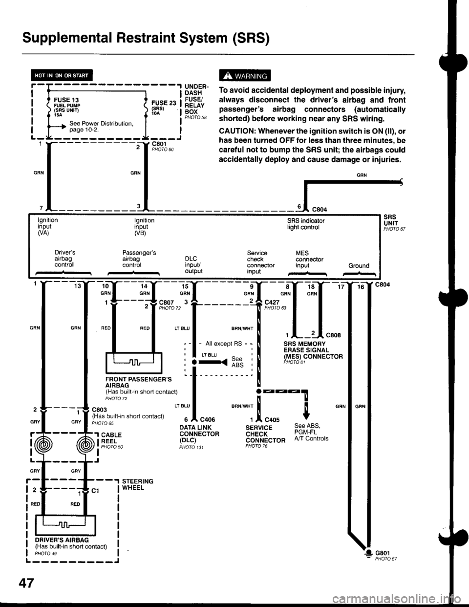
Supplemental Restraint System (SRS)
FUSE 13FUEL PUIIP(SRS UNF)t5a
FUS€ 23(s8s)
ts13t5" To avoid accidental deployment and possible iniury,
lq9Fr. always disconnect the driver's airbag and frontg[f" pas"Lnger's airbag connectors (automaticallyPHorQ 58 shorted) before working near any SRS witing.
CAUTION: Whenever the ignition switch is ON (ll), ol
has been turned OFF tor less than three minutes, be
careful not to bump the SRS unit; the airbags could
accidentally deploy and cause damage or iniuries.
{-
lgnitionrnpul(VA)
tgnitionInpul(VB)
Passenger'sarrbagcontrol
SFIS indicaiorlight control
Service MEScheck @nnectorconnector input GroundInpu
Driver'sarrbagconlr0lDLC'npuvoutput
-ro--Y---la-Y--- 16
:ffi*f:ffq
lJnor,rrpassencen= 'l t- 'i
rHas bu,ll 'n shorl contac0
I j:::T
fn'"o"t. n-n .non "on,""u
" "'Jl
"oou
""" ""]
.!, "oou $
cRN
: :3<::" :l (Y.e_er
oArA LINK sERvrcE 9qe l-qs,'l SABLE coHrecibn aH;a'i- ?9q1i iEEi- 1ot-i1 cijrlt't'ecron n/r contrors
I Pt:OfO 5a pqara t Jt PForo 76
I
STEERINGWHEEL
1
GRY
ON|vER'S AIRBAG(Has built-in short contact)
L---------J
47
GBY
r
I
I
GRY
2
NED
Page 1476 of 1681

Air Deliver| (cont'd)
- How the Circuit Works
The air delivery system directs the flow of air used
by the heater and air conditioner systems.
Mode Selection
Mode selection is controlled by the mode switches in
the heater control panel and the mode control motor.
When you select a specific mode, voltage is applied
through the dimming control circuit to the LED, which
comes on, indicating the mode selected. Ground is
provided to the mode control motor though that
mode switch. The motor then runs until the air
control door reaches the proper position.
Fresh/Recirculation Selection
When you press the recirculation button, a ground
signal is sent from the heater control panel to the
recirculation control motor. The motor lhen runs
until the recirculation door reaches the opposite
Dosition. When the recirculation button is in the
REC position, battery voltage is applied through the
dimming control circuit to the recirculate LED, and
the LED comes on.
Refer to the Service Manual (Section 21, Heate0 for
specif ic tests or troubleshooting procedures.
61-2
Page 1479 of 1681

A/C Gompressor Controls (conrd)
- How the Circuit Works
Battery voltage is supplied through fuse 56 to the
A,/C compressor clutch relay contacts at all times.
With the ignition switch in ON (ll), voltage is applied
to the coil of the A,/C compressor clutch relay
through fuse 17. When you push the A,/C switch
ON, and the heater fan switch is in posation 1, 2, 3,
or 4, a "ground" input is provided to the engine or
powertrain control module (ECM or PCM) through
the A,/C thermostat and the A,/C pressure switch.
The A,/C compressor clutch relay is grounded by the
engine or powertrain control module (ECM or PCM).
When energized, the A,/C compressor clutch relay
allows battery voltage to turn on the A,/C
comDressor clutch,
The A,/C ON indicator light comes on when the A"/C
system is requested.
A,/C Thermostat
The A,/C thermostat is located on the evaoorator
housing. The AJC thermostat turns off the A,/C
compressor clutch if the temperature at the
evaporator goes below 3'C (37'F). This prevents
condensation from freezing on the evaporator fins
and blocking the air delivery into the passenger
compartment. The blower motor will keep running
when the sensor lurns off the compressor.
A,/C Pressure Switch
The A,/C pressure switch is located in the condenser
outlet line where refrigerant is in a high
temperature/high pressure liquid state. The switch
will sense abnormally high or low pressure, and
open the circuit. This removes ground, and the
compressor will stop running.
Refer to the Service Manual (Section 22,
Air Conditioning) for specific tests or
troubleshooting procedures.
62-2
Page 1483 of 1681

Fans (cont'd)
- How the Gircuit Works
When the ignition switch is in ON (ll), voltage is
applied to the coils of the radiator fan relay and the
condenser fan relay (with A,/C) through fuse 17.
Whenever a ground is provided to the radiator fan
relay and condenser fan relay, the relays are
energized, turning on the radiator fan motor and
condenser fan motor. The relays can be grounded
by the radiator fan switch, engine or powertrain
control module (ECM or PCM) (USA), or the A,/C
and heater lan switches via the A'lC pressure switch
and the A,/C lhermostat.
A,/C Thermostat
The A,/C thermostat is located on the evaporator
housing. The A/C thermostat turns oft the A/C
compressor clutch it the temperature at the
evaporator goes below 3'C (37"F). This prevents
condensalion from freezing on the evaporator fins
and blocking the air delivery into the passenger
compartment. lt the temperature goes below 3'C
(37'F) turning off the A"/C thermostat, and the
BLU/RED wire at the A,/C diode was the only wire
providing ground to the condenser and radiator
fan relays (A,/C switch on, heater fans switch on,
radiator fan switch open, and ECM or PCM fan
controi output not grounded), the relay will
deenergize removing voltage from the condenser
and radiator fan motors causing them to stop
running.
A,/C Pressure Switch
The AJC oressure switch is located in the condenser
outlet line where refrigerant is in a high
temperature/high pressure liquid state. The A,/C
switch turns off the A,/C compressor clutch if it
senses abnormally high or low pressure. lf the A'lC
pressure switch opens, and the BLU/RED wire at
the A/C diode was the only wire providing ground
to the condenser and radiator fan relays (L/C switch
on, heater fans switch on, radiator lan switch open'
and ECM or PCM fan control output not grounded),
the relay will deenergize removing voltage from the
condenser and radiator fan motors causing them to
stop running.
A./C Diode
This diode orevents the radiator fan switch f rom
grounding the "A'lC ON" input to the engine or
powertrain control module (ECM or PCM).
Refer to the Service Manual (Section 23, Electrical)
for specific tests or troubleshooting procedures.
63-3
Page 1485 of 1681
- How the Circuit Works
Voltage is applied at all times through f use 50 to
the rear window defogger relay. With the ignition
swrtch in ON (ll), voltage is applied through luse
16 to the rear window defogger relay and the
defogger ON indicator.
When you turn the rear window defogger switch to
ON, a path to ground is provided for the rear
window defogger relay and the defogger ON
indicator through the integrated control unit. The
defogger ON indicator light comes on and the rear
window detogger relay contacts close. Voltage is
applied to the detogger grid on the surface of the
rear window and the grid heats the rear window to
remove any fog lrom the glass.
A timer in the integrated control unit will automatically
tum off the defogger atter 20 to 30 minutes.
Refer to the Service Manual (Section 23, Electrical)
for specific tests or troubleshooting procedures.
64-1