Page 1542 of 1681
- How The Circuit Wo
With the ignition switch ON (ll), voltage is applied
through fuse 24 to the coil of the moonroof relay.
The moonroof relay energizes and voltage is
applied from fuse 49 through the closed contacts of
the moonroof relay to the moonroof switch.
Open Operation
When you push the moonroof switch to the OPEN
position, voltage is applied to the moonroof motor.
The moonroot motor is grounded through the
CLOSE contacts of the moonroof switch, and the
motor runs to open the moonroof
Close Operation
When you push moonroof switch to the CLOSE
position, voltage is applied to the moonroof motor.
The moontoof motor is grounded through the OPEN
contacts of the moonroof switch, and the motor runs
to close the moonroof.
Refer to the Service Manual (Section 23, Electrical)
for specific tests or troubleshooting procedures.
122-1
Page 1548 of 1681
- How the Circuit Works
The immobilizer system is designed to prevent the
car f rom being started without the owner's ignition
key. lf an attempt is made to start the car without
the correct key, the immobilizer system will disable
the car's fuel supply.
The immobilizer system consists of the ignition key,
immobilizer receiver unit, immobilizer indicator
light, PGM-FI main relay, fuel pump, and the PCM
or ECM.
With the ignition switch in ON (ll) or START (lll), the
immobilizer receiver unit and the PCM or ECM
receive an "ignition on" signal through fuse 44 and
the PGM-FI main relay. The PCM or ECM then
sends power to the ignition key transponder through
the immobilizer receiver unit. The transponder then
sends a coded signal back to the PCM or ECM
through the receiver unit. lf the signal is correct, the
PCM or ECM will energize the car's fuel supply
system by grounding the PGM-FI main relay. The
immobilizer indicator light flashes a code to indicate
that the correct key has been inserted. lf the
ignition key signal is not correct, the PCM or ECM
will not energize the car's fuel supply system by not
grounding the PGM-Fl main relay. The immobilizer
indicator light then flashes a code to indicate that an
incorrect key has been inserted.
Refer to the Service Manual (Section 23,
Body Electrical) for specific tests and
troubleshooting procedures.
132-1
Page 1558 of 1681
lnterlock System
- How the Circuit Works
Key Interlock
Battery voltage is supplied at all times through f use
33 to the key interlock switch. When the key is in
the ignition, battery voltage is supplied to the key
intedock solenoid and the key interlock circuit in the
interlock control unit. When the A/T gear position
switch is in PABK, ground is provided to the key
interlock circuit. This removes ground from the
interlock solenoid, the solenoid is deenergized, and
the key can be removed from the ignition.
Shift Position Interlock
Battery voltage is supplied at all times lrom fuse 52
to the brake switch. With the ignition in ON (ll) or
START (lll), battery voltage is supplied through luse
25 to the shift lock solenoid. When you push the
brake pedal, battery voltage is applied through the
GRN/VVHT wire to the transmission ('98-�99 models)
or powertrain ('00 model) control module (TCM or
PCM). lf, at the same time, you do not push the
accelerator pedal, a low voltage signal is sent
through the RED/BLK wire to the TCM or PCM. The
TCM or PCM then applies voltage through the
WHT/RED wire to the shift lock circuit in the
interlock control unit. lf the A,/T gear position switch
is in the PARK position, the shift lock circuit
provides ground to the shift lock solenoid. The
solenoid is then energized, and the shift lever can
be moved from the PARK Dosition.
Refer to the Service Manual (Section 23, Electrical)
for specific tests or troubleshooting procedures.
138-2
Page 1561 of 1681
Power Mirrors
- How the Gircuit Works
The two outside mirrors are controlled by the power
minor switch. Each mirror has two reversible
motors: one motor moves the mirror uo and down
and the other motor moves the mirror left and right.
The oower mirror switch contains three switches lo
control mirror direction, and two switches to select
the left or right mirror. With the ignition in ON (ll),
battery voltage is supplied to the power mirror
switch. The mirror selector switch directs voltage
from two of the direction switches to either the left
or the right minor. Each direction switch is used for
more than one function.
Mirror Up Operation
With the power mirror switch in the up position,
switch 1 is moved to the A oosition. Switch 1
applies battery voltage to both the left and right
power mirror up/down motors. lf the mirror selector
switch is in the left position, the left up/down motor
is grounded through the mirror selector switch and
switch 2 in the B position to G501 (Sedan) or G502
(Hatchback). lf the right mirror up/down motor is
selected il is also grounded through switch 2 in the
B position.
Mirror Down Operation
With the power mirror switch in the down position,
switches 2 and 3 are moved to the A position.
Switch 2 applies battery voltage to the left or right
power mirror up/down motor as determined by the
mirror selector switch. The selected mirror motor is
grounded through switch I in the B position to G501
(Sedan) or G502 (Hatchback). When switch 2 is
moved to position A, it also applies battery voltage
to the selected mirror lefyright motor. With switch 3
in the A position, battery voltage is supplied to both
sides of the leruright motor so it does not move.
Mirror Left Operation
With the power mirror switch in the left position,
switches 1 and ? ate moved to the A oosition.
Switch 2 applies battery voltage to the left or right
power mirror lefvright motor as determined by the
mirror selector switch. The selected mirror motor is
grounded through switch 3 in the B position to G501
(Sedan) or G502 (Hatchback). When switch 2 is
moved to position A, it also applies battery voltage
to the selected mirror up/down molor. With switch 1
in the A position, battery voltage is supplied to both
sides of the uD/down motor so it does not move.
Mirror Right Operation
With the power mirror switch in the right position,
switch 3 is moved to the A position. Switch 3
applies battery voltage through the mirror selector
switch to the left or right lefvright motor. The
motor is grounded through the mirror selector
switch and switch 2 in the B oosition to G501
(Sedan) or G502 (Hatchback).
Refer to the Service Manual (Section 23, Electrical)
for specific tests or troubleshooting procedures.
141-2
Page 1606 of 1681
Connector ldentification and Wire Harness Routing (cont'd)
Connector
oI
Terminal
Number of
Cavities/
Color
LocationConnects toNotes
Main Wire Harness (Right branch)
c401
c402
c403
c404
c405
c407
c408
c409
c410
c457
25-GRY
3-WHT
2.BRN
1O-GRY
2-BLU
22-ORN
32-GRY
31-BLU
16-GRY
25-GRY
Front passengels door
Under right side of dash
Under right side of dash
Under right side of dash
Under right side of dash
Behind right kick panel
Behind right kick panel
Behind right kick panel
Behind right kick panel
Behind right kick panel
Fronl passenger's door wirenarness
A,/C diode
Heater sub-harness A
Heater sub-harness A
Service check connector
ABS sub-harness
Engine control module (ECM/PCM)
Engine control module (ECM/PCM)
Engine control module (ECM/PCM)
Engine control module (ECM/PCM)
. = All exceot '00 model w/ M/T
203-10
Page 1643 of 1681
\
\
Specifications
Standards and Service Limits .............. g-2
Design Specifications 3-15
Body Specifications ... 3-18
Page 1644 of 1681
I
I
Standards and Service Limits
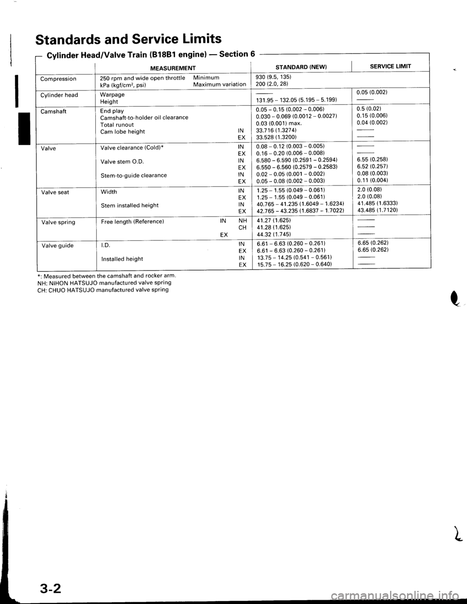
Cylinder Head/Valve Train (B18Bl engine)Section 6
*: Measured between the camshaft and rocker arm.
NH: NIHON HATSUJO manufactured valve spring
CH: CHUO HATSUJO manufactured valve spring
MEASUREMENTSTANDARD (NEW) I SERVICE LIMIT
Compression250 rpm and wide open throttle Minimum
kPa (kgf/cm'�, psi) Maximum variation930 (9.5, 135)200 Q.0,281
Cylinder headWarpageHeightta,|* - 132.05 (5.195 - 5.199)0.05 (0.002)
CamshaftEnd playCamshaft-to-holder oil clearanceTotal runoutCam lobe height lNEX
0.05 - 0.15 (0.002 - 0.006)0.030 - 0.069 (0.0012 - 0.0027)0.03 (0.001) max.33.7 16 11.327 4l33.528 ( 1.3200)
0.5 (0.02)
0.15 (0.006)
0.04 (0.002)
ValveValve clearance (Cold)" lNEX
Valve stem O.D. lNEX
Stem-to-guide clearance lNEX
0.08 - 0.12 (0.003 - 0.005)0.16 - 0.20 (0.006 - 0.00816.580 - 6.590 (0.2591 - 0.2594)6.550 - 6.560 (0.2579 - 0.2583)
0.02 - 0.05 (0.001 - 0.002)0.05 - 0.08 (0.002 - 0.003)
ouu to.rutt6.52 rc.2571.0.08 (0.003)
0.1 1 (0.004)
Valve seatwidth lNEX
stem installed height lNEX
1 .25 - 1.55 (0.049 - 0.061 )1.25 - 1 .55 (0.049 - 0.061 )40.765 - 41.235 (1.6049 - 1.6234142J65 - 43.235 (1.6837 - 1.70221
2.0 (0.08)
2.0 (0.08)
41.485 (1.6333)
43.485 (1.71201
Valve springFree length (Reference)IN NHCHEX
41.27 (1.6251
41.28 (1.625)
44.32 t1-7 451
Valve guidet.D. lNEX
Installed height lNEX
6.61 - 6.63 (0.260 - 0.261)6.61 - 6.63 (0.260 - 0.261)13.7 5 - 1 4.25 (0.541 - 0.561 )15.75 - 16.25 (0.620 - 0.640)
6.6s (0.262)
6.65 (0.262)
Page 1645 of 1681
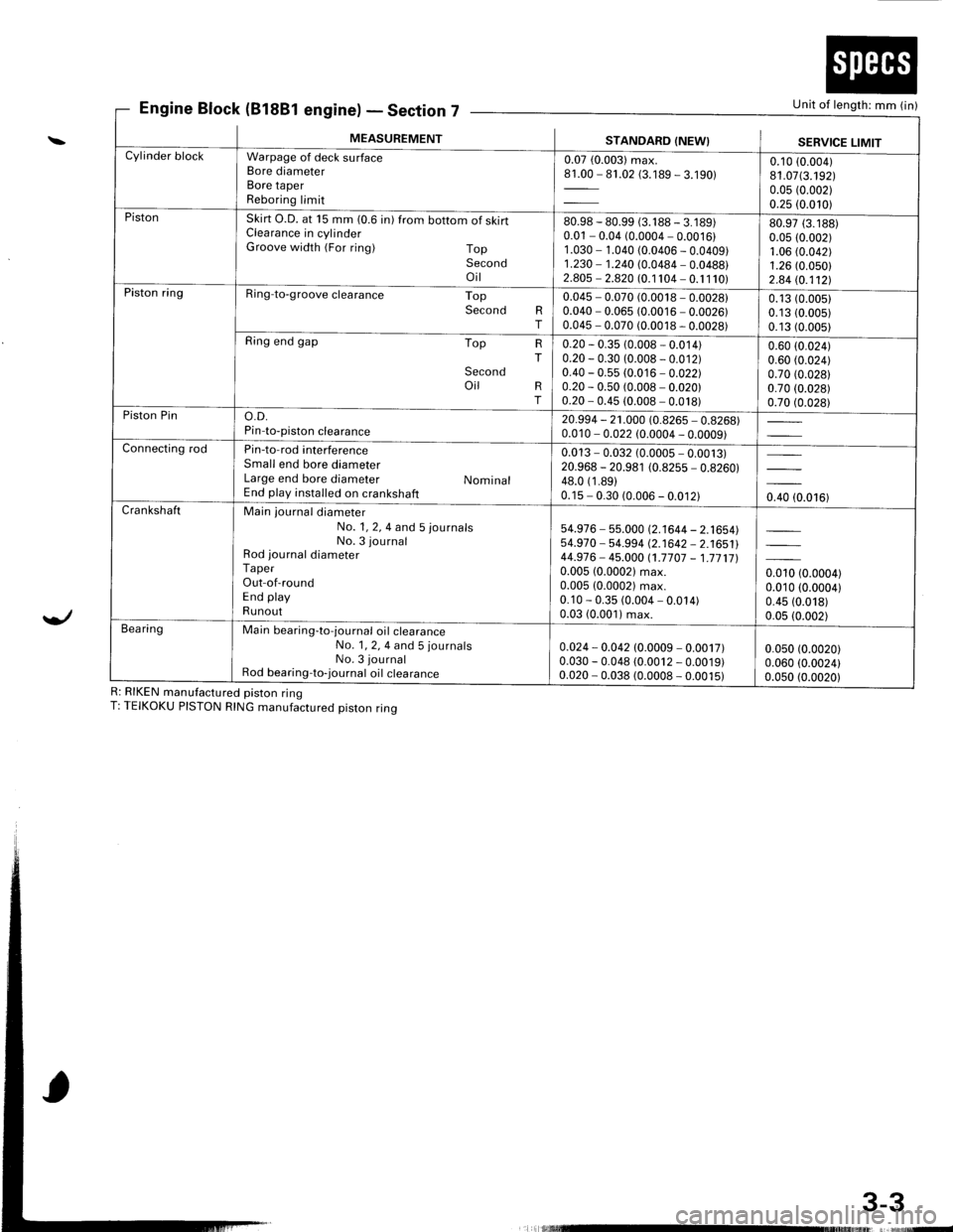
Engine Block (81881 engine)Section 7Unit of length: mm (in)
3-3
\
Yl
R: RIKEN manufactured piston ringT: TEIKOKU PISTON RING manufactured piston ring
E' - Declror
MEASUREMENTSTANDARD (NEW}SERVICE LIMITCylinder blockWarpage of deck surfaceBore diameterBore taperReboring limit
0.07 (0.003) max.81.00 - 81.02 (3.189 - 3.190)0.10 (0.004)
81.07(3.192)0.05 (0.002)
0.25 (0.010)PistonSkirt O.D. at 15 mm (0.6 in) from bottom of skirtClearance in cylinderGroove width (For ring) TopSecondoil
80.98 - 80.99 (3. 1 88 - 3. 1 89)0.01 - 0.04 (0.0004 - 0.0016)1 .030 - 1.040 (0.0406 - 0.0409)1.230 - 1.240 (0.0484 - 0.0488)2.805 - 2.820 (0.1 104 - 0. 1 1 10)
80.97 (3.188)
0.05 (0.002)1.06 (0.042)
1.26 (0.050)
2.84 (0.112!.Piston ringRing-to-groove clearance TopSecond RT
0.045 - 0.070 (0.0018 - 0.0028)0.040 - 0.065 (0.0016 - 0.0026)0.045 - 0.070 (0.0018 - 0.0028)
0.13 (0.0051
0.13 (0.005)
0.13 (0.005)
Ring end gap Top
Secondoil
HT
RT
0.20 - 0.35 (0.008 - 0.014)0.20 - 0.30 (0.008 - 0.012)0.40 - 0.55 (0.016 - 0.022)0.20 - 0.50 (0.008 - 0.020)0.20 - 0.45 (0.008 - 0.018)
0.60 (0.024)
0.60 (0.024)
0.70 (0.028)
0.70 (0.028)
0.70 (0.028)Piston Pino.D.Pin-to-piston clearance20.994 - 21.000 (0.8265 - 0.8268)0.010 - 0.022 (0.0004 - 0.0009)Connecting rodPin-to-rod interferenceSmall end bore diameterLarge end bore diameter NominalEnd play installed on crankshaft
0.013 - 0.032 (0.0005 - 0.0013)20.968 - 20.981 (0.8255 - 0.8260)48.0 (1 .89)0.15 - 0.30 (0.006 - 0.012)0.40 (0.016)CrankshaftMain journal diameterNo. 1, 2, 4 and 5 journalsNo. 3 journalRod journal diameterTaperOut-of-roundEnd playRunout
54.976 - 55.000 (2.1644 - 2.1654)54.970 - 54-994 (2.1642 - 2.1651144.976- 45.000 (1.7707 - 1.771710.005 (0.00021 max.0.005 (0.0002) max.0.10 - 0.35 (0.004 - 0.014)0.03 (0.001) max.
0.010 (0.0004)0.010 (0.0004)
0.45 (0.018)
0.05 (0.002)Bea ringMain bearing-to-journal oil crearanceNo. 1, 2, 4 and 5 journalsNo. 3 journalRod bearing-to-journal oil crearance
0.024 - 0.042 (0.0009 - 0.0017)0.030 - 0.048 (0.0012 - 0.0019)0.020 - 0.038 (0.0008 - 0.0015)
0.050 (0.0020)
0.060 (0.0024)0.0s0 (0.0020)
L rlllllllllrltruE