Page 5 of 1807
CL047-01
Q04338
CL-12
- CLUTCHCLUTCH RELEASE CYLINDER
1553 Author�: Date�:
1997 SUPRA (RM502U)
DISASSEMBLY
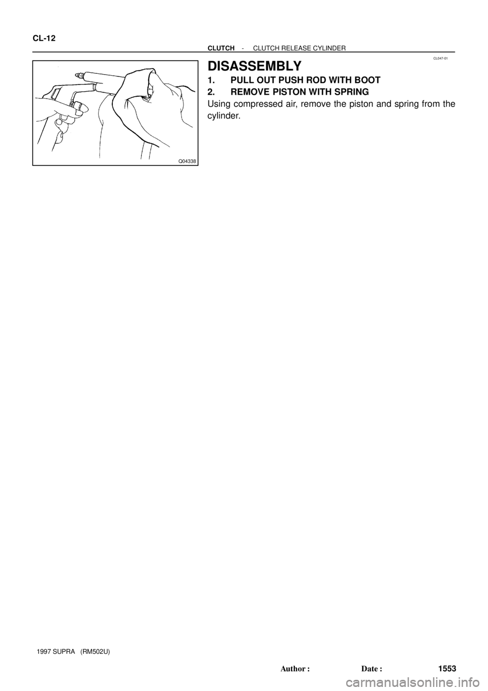
1. PULL OUT PUSH ROD WITH BOOT
2. REMOVE PISTON WITH SPRING
Using compressed air, remove the piston and spring from the
cylinder.
Page 6 of 1807
CL048-01
Z07291
- CLUTCHCLUTCH RELEASE CYLINDER
CL-13
1554 Author�: Date�:
1997 SUPRA (RM502U)
REASSEMBLY
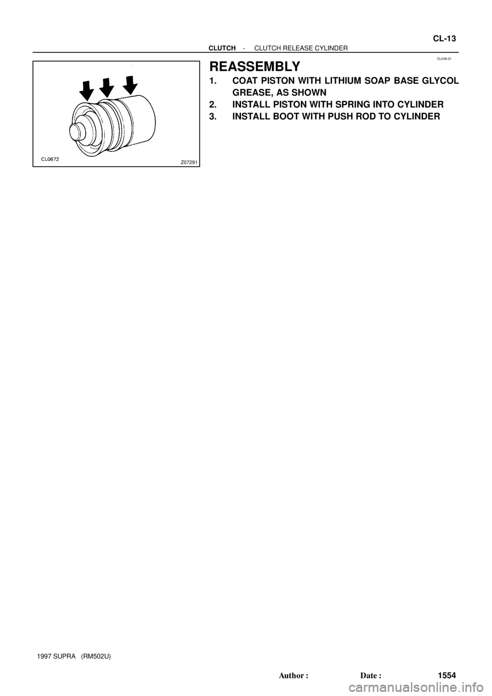
1. COAT PISTON WITH LITHIUM SOAP BASE GLYCOL
GREASE, AS SHOWN
2. INSTALL PISTON WITH SPRING INTO CYLINDER
3. INSTALL BOOT WITH PUSH ROD TO CYLINDER
Page 17 of 1807
CL040-01
Z16903
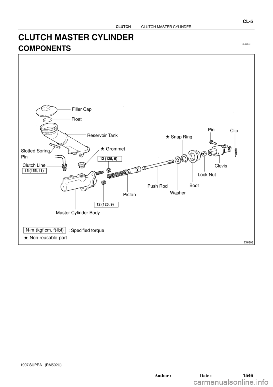
Filler Cap
Reservoir Tank
Slotted Spring
Pin
Clutch Line
Push Rod � Grommet Float
Clip Pin
Clevis
Boot
Washer
� Snap Ring
Lock Nut15 (155, 11)
12 (125, 9)
12 (125, 9)
N´m (kgf´cm, ft´lbf)
: Specified torque
� Non-reusable partPiston
Master Cylinder Body
- CLUTCHCLUTCH MASTER CYLINDER
CL-5
1546 Author�: Date�:
1997 SUPRA (RM502U)
CLUTCH MASTER CYLINDER
COMPONENTS
Page 19 of 1807
CL042-01
Q04189
Q04190
- CLUTCHCLUTCH MASTER CYLINDER
CL-7
1548 Author�: Date�:
1997 SUPRA (RM502U)
DISASSEMBLY
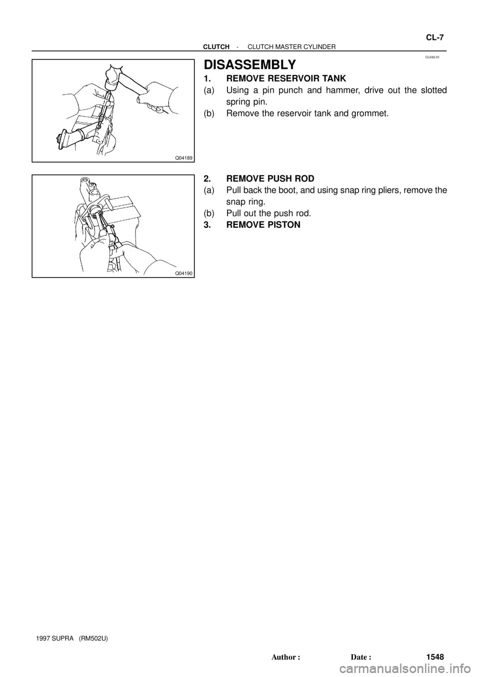
1. REMOVE RESERVOIR TANK
(a) Using a pin punch and hammer, drive out the slotted
spring pin.
(b) Remove the reservoir tank and grommet.
2. REMOVE PUSH ROD
(a) Pull back the boot, and using snap ring pliers, remove the
snap ring.
(b) Pull out the push rod.
3. REMOVE PISTON
Page 20 of 1807
CL044-01
Z08053
Q04313
Protrusion
1.5 - 3.5 mm
(0.059 - 0.138 in.) CL-8
- CLUTCHCLUTCH MASTER CYLINDER
1549 Author�: Date�:
1997 SUPRA (RM502U)
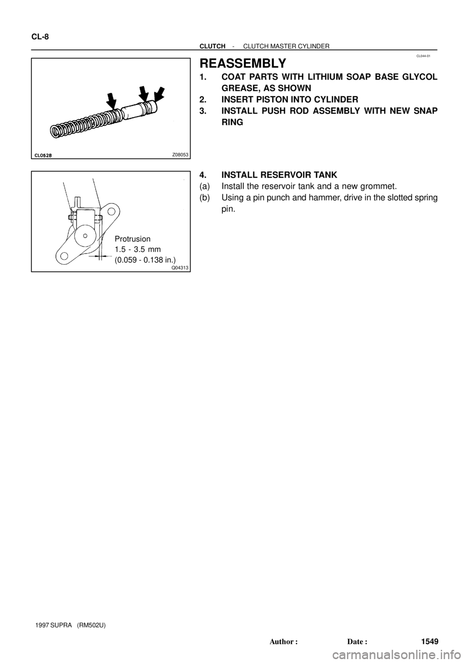
REASSEMBLY
1. COAT PARTS WITH LITHIUM SOAP BASE GLYCOL
GREASE, AS SHOWN
2. INSERT PISTON INTO CYLINDER
3. INSTALL PUSH ROD ASSEMBLY WITH NEW SNAP
RING
4. INSTALL RESERVOIR TANK
(a) Install the reservoir tank and a new grommet.
(b) Using a pin punch and hammer, drive in the slotted spring
pin.
Page 48 of 1807
IN04A-01
N17080
Filler Cap
Float
Reservoir Tank
� Grommet
Clip
Slotted Spring Pin
N´m (kgf´cm, ft´lbf) : Specified torque
� Non-reusable partCylinder
Piston
Push Rod
Washer
Snap Ring
Boot
� Gasket
Lock Nut
Clevis Pin
Clevis
12 ( 120, 9)
15 ( 155, 11)
- INTRODUCTIONHOW TO USE THIS MANUAL
IN-1
1 Author�: Date�:
1997 SUPRA (RM502U)
HOW TO USE THIS MANUAL
GENERAL INFORMATION
1. INDEX
An INDEX is provided on the first page of each section to guide you to the item to be repaired. To assist you
in finding your way through the manual, the Section Title and major heading are given at the top of every
page.
2. GENERAL DESCRIPTION
At the beginning of each section, a General Description is given that pertains to all repair operations con-
tained in that section.
Read these precautions before starting any repair task.
3. TROUBLESHOOTING
TROUBLESHOOTING tables are included for each system to help you diagnose the problem and find the
cause. The fundamentals of how to proceed with troubleshooting are described on page IN-17. Be sure to
read this before performing troubleshooting.
4. PREPARATION
Preparation lists the SST (Special Service Tools), recommended tools, equipment, lubricant and SSM (Spe-
cial Service Materials) which should be prepared before beginning the operation and explains the purpose
of each one.
5. REPAIR PROCEDURES
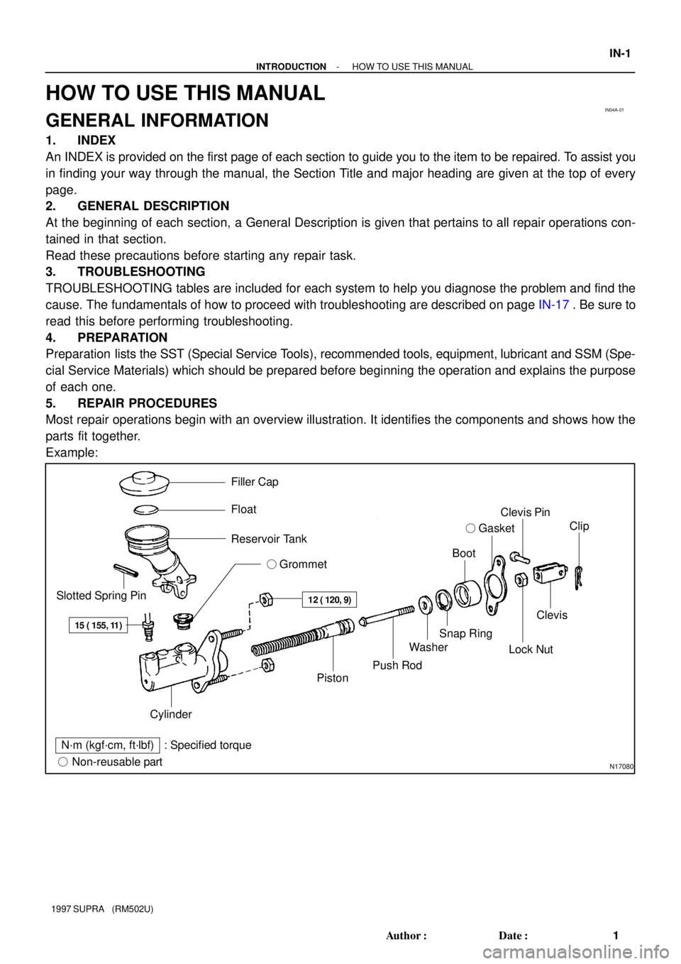
Most repair operations begin with an overview illustration. It identifies the components and shows how the
parts fit together.
Example:
Page 49 of 1807

Illustration:
what to do and where
21. CHECK PISTON STROKE OF OVERDRIVE BRAKE
(a) Place SST and a dial indicator onto the overdrive brake
piston as shown in the illustration.
Task heading : what to do
SST 09350-30020 (09350-06120)
Set part No. Component part No.
Detailed text : how to do task
(b) Measure the stroke applying and releasing the compressed
Piston stroke: 1.40 � 1.70 mm (0.0551 � 0.0669 in.)
Specification
air (392 - 785 kPa, 4 - 8 kgf.cm2 or 57 - 114 psi) as
shown in the illustration. IN-2
- INTRODUCTIONHOW TO USE THIS MANUAL
2 Author�: Date�:
1997 SUPRA (RM502U)
The procedures are presented in a step-by-step format:
�The illustration shows what to do and where to do it.
�The task heading tells what to do.
�The detailed text tells how to perform the task and gives other information such as specifications
and warnings.
Example:
This format provides the experienced technician with a FAST TRACK to the information needed. The upper
case task heading can be read at a glance when necessary, and the text below it provides detailed informa-
tion. Important specifications and warnings always stand out in bold type.
6. REFERENCES
References have been kept to a minimum. However, when they are required you are given the page to refer
to.
7. SPECIFICATIONS
Specifications are presented in bold type throughout the text where needed. You never have to leave the
procedure to look up your specifications. They are also found in Service Specifications section, for quick
reference.
�CAUTIONS are presented in bold type, and indicate there is a possibility of injury to you or other
people.
�NOTICES are also presented in bold type, and indicate the possibility of damage to the compo-
nents being repaired.
�HINTS are separated from the text but do not appear in bold. They provide additional information
to help you perform the repair efficiently.
8. SI UNIT
The UNITS given in this manual are primarily expressed according to the SI UNIT (International System of
Unit), and alternately expressed in the metric system and in the English System.
Example:
Torque: 30 N´m (310 kgf´cm, 22 ft´lbf)
Page 273 of 1807
BO0QI-01
N08508
100 mm (3.94 in.)
Hole Here
N08509
Adhesive BO-16
- BODYBACK DOOR
2096 Author�: Date�:
1997 SUPRA (RM502U)
REPLACEMENT
1. REMOVE ROOF SIDE INNER GARNISH
(See page BO-14)
2. REMOVE DAMPER STAY
NOTICE:
When handling the damper.
�Do not disassemble the damper because the cylinder
is filled with pressurized gas.
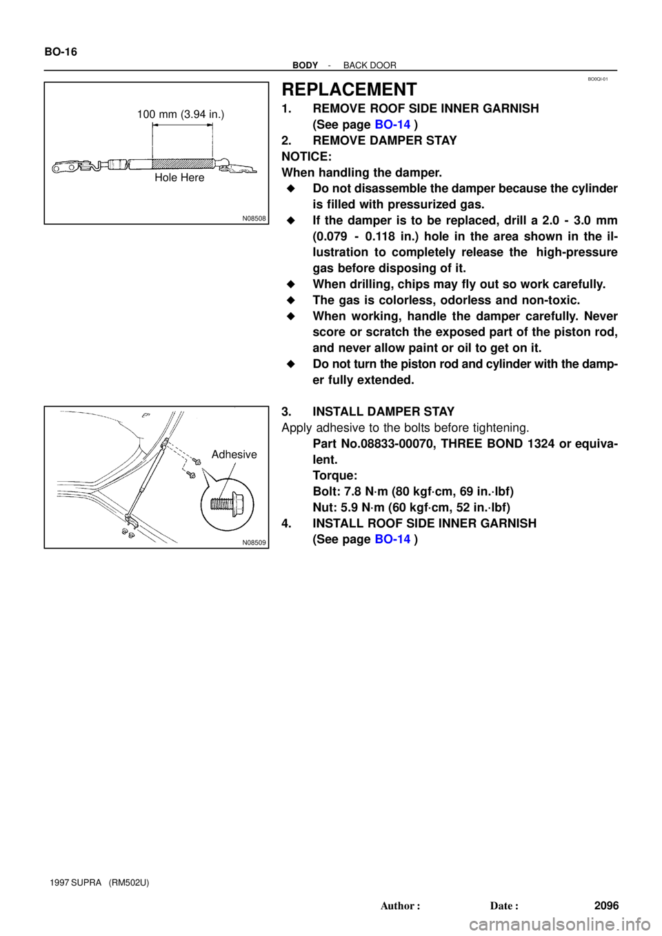
�If the damper is to be replaced, drill a 2.0 - 3.0 mm
(0.079 - 0.118 in.) hole in the area shown in the il-
lustration to completely release the high-pressure
gas before disposing of it.
�When drilling, chips may fly out so work carefully.
�The gas is colorless, odorless and non-toxic.
�When working, handle the damper carefully. Never
score or scratch the exposed part of the piston rod,
and never allow paint or oil to get on it.
�Do not turn the piston rod and cylinder with the damp-
er fully extended.
3. INSTALL DAMPER STAY
Apply adhesive to the bolts before tightening.
Part No.08833-00070, THREE BOND 1324 or equiva-
lent.
Torque:
Bolt: 7.8 N´m (80 kgf´cm, 69 in.´lbf)
Nut: 5.9 N´m (60 kgf´cm, 52 in.´lbf)
4. INSTALL ROOF SIDE INNER GARNISH
(See page BO-14)