Page 1291 of 1807
Z02456
45° 75°
Width
P02126
Z02457
Deviation
EM0801
EM0281
- ENGINE MECHANICAL (2JZ-GTE)CYLINDER HEAD
EM-39
1144 Author�: Date�:
1997 SUPRA (RM502U)
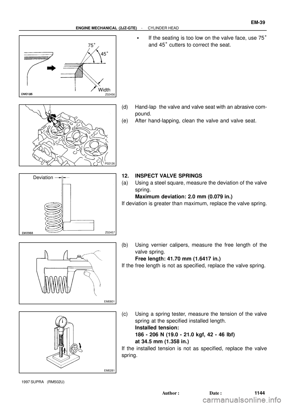
�If the seating is too low on the valve face, use 75°
and 45° cutters to correct the seat.
(d) Hand-lap the valve and valve seat with an abrasive com-
pound.
(e) After hand-lapping, clean the valve and valve seat.
12. INSPECT VALVE SPRINGS
(a) Using a steel square, measure the deviation of the valve
spring.
Maximum deviation: 2.0 mm (0.079 in.)
If deviation is greater than maximum, replace the valve spring.
(b) Using vernier calipers, measure the free length of the
valve spring.
Free length: 41.70 mm (1.6417 in.)
If the free length is not as specified, replace the valve spring.
(c) Using a spring tester, measure the tension of the valve
spring at the specified installed length.
Installed tension:
186 - 206 N (19.0 - 21.0 kgf, 42 - 46 lbf)
at 34.5 mm (1.358 in.)
If the installed tension is not as specified, replace the valve
spring.
Page 1292 of 1807
P04463
EM2011
EM2538
P02141
P02360
Plastigage EM-40
- ENGINE MECHANICAL (2JZ-GTE)CYLINDER HEAD
1145 Author�: Date�:
1997 SUPRA (RM502U)
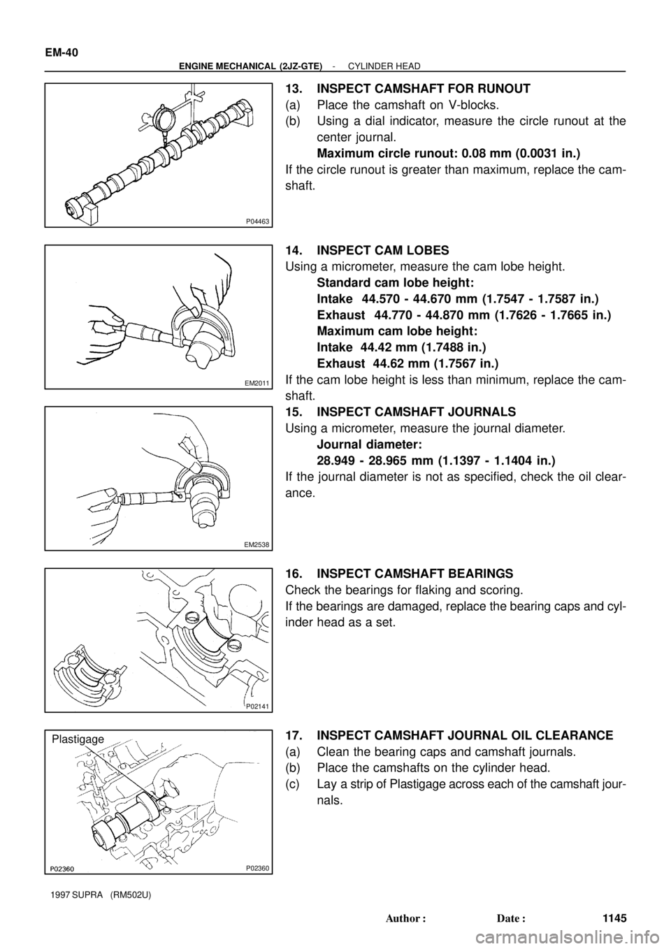
13. INSPECT CAMSHAFT FOR RUNOUT
(a) Place the camshaft on V-blocks.
(b) Using a dial indicator, measure the circle runout at the
center journal.
Maximum circle runout: 0.08 mm (0.0031 in.)
If the circle runout is greater than maximum, replace the cam-
shaft.
14. INSPECT CAM LOBES
Using a micrometer, measure the cam lobe height.
Standard cam lobe height:
Intake 44.570 - 44.670 mm (1.7547 - 1.7587 in.)
Exhaust 44.770 - 44.870 mm (1.7626 - 1.7665 in.)
Maximum cam lobe height:
Intake 44.42 mm (1.7488 in.)
Exhaust 44.62 mm (1.7567 in.)
If the cam lobe height is less than minimum, replace the cam-
shaft.
15. INSPECT CAMSHAFT JOURNALS
Using a micrometer, measure the journal diameter.
Journal diameter:
28.949 - 28.965 mm (1.1397 - 1.1404 in.)
If the journal diameter is not as specified, check the oil clear-
ance.
16. INSPECT CAMSHAFT BEARINGS
Check the bearings for flaking and scoring.
If the bearings are damaged, replace the bearing caps and cyl-
inder head as a set.
17. INSPECT CAMSHAFT JOURNAL OIL CLEARANCE
(a) Clean the bearing caps and camshaft journals.
(b) Place the camshafts on the cylinder head.
(c) Lay a strip of Plastigage across each of the camshaft jour-
nals.
Page 1293 of 1807
P02166
P02268
P02167
P02264
- ENGINE MECHANICAL (2JZ-GTE)CYLINDER HEAD
EM-41
1146 Author�: Date�:
1997 SUPRA (RM502U)
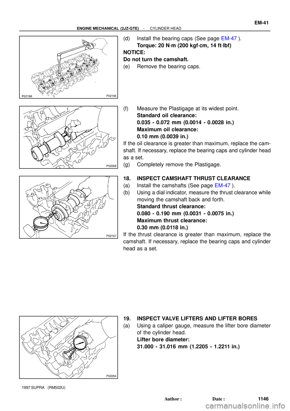
(d) Install the bearing caps (See page EM-47).
Torque: 20 N´m (200 kgf´cm, 14 ft´lbf)
NOTICE:
Do not turn the camshaft.
(e) Remove the bearing caps.
(f) Measure the Plastigage at its widest point.
Standard oil clearance:
0.035 - 0.072 mm (0.0014 - 0.0028 in.)
Maximum oil clearance:
0.10 mm (0.0039 in.)
If the oil clearance is greater than maximum, replace the cam-
shaft. If necessary, replace the bearing caps and cylinder head
as a set.
(g) Completely remove the Plastigage.
18. INSPECT CAMSHAFT THRUST CLEARANCE
(a) Install the camshafts (See page EM-47).
(b) Using a dial indicator, measure the thrust clearance while
moving the camshaft back and forth.
Standard thrust clearance:
0.080 - 0.190 mm (0.0031 - 0.0075 in.)
Maximum thrust clearance:
0.30 mm (0.0118 in.)
If the thrust clearance is greater than maximum, replace the
camshaft. If necessary, replace the bearing caps and cylinder
head as a set.
19. INSPECT VALVE LIFTERS AND LIFTER BORES
(a) Using a caliper gauge, measure the lifter bore diameter
of the cylinder head.
Lifter bore diameter:
31.000 - 31.016 mm (1.2205 - 1.2211 in.)
Page 1294 of 1807
EM2196
A02166
P12544
P12281P12281
A02828
About
50 mm
Compressed
Thread
EM-42
- ENGINE MECHANICAL (2JZ-GTE)CYLINDER HEAD
1147 Author�: Date�:
1997 SUPRA (RM502U)
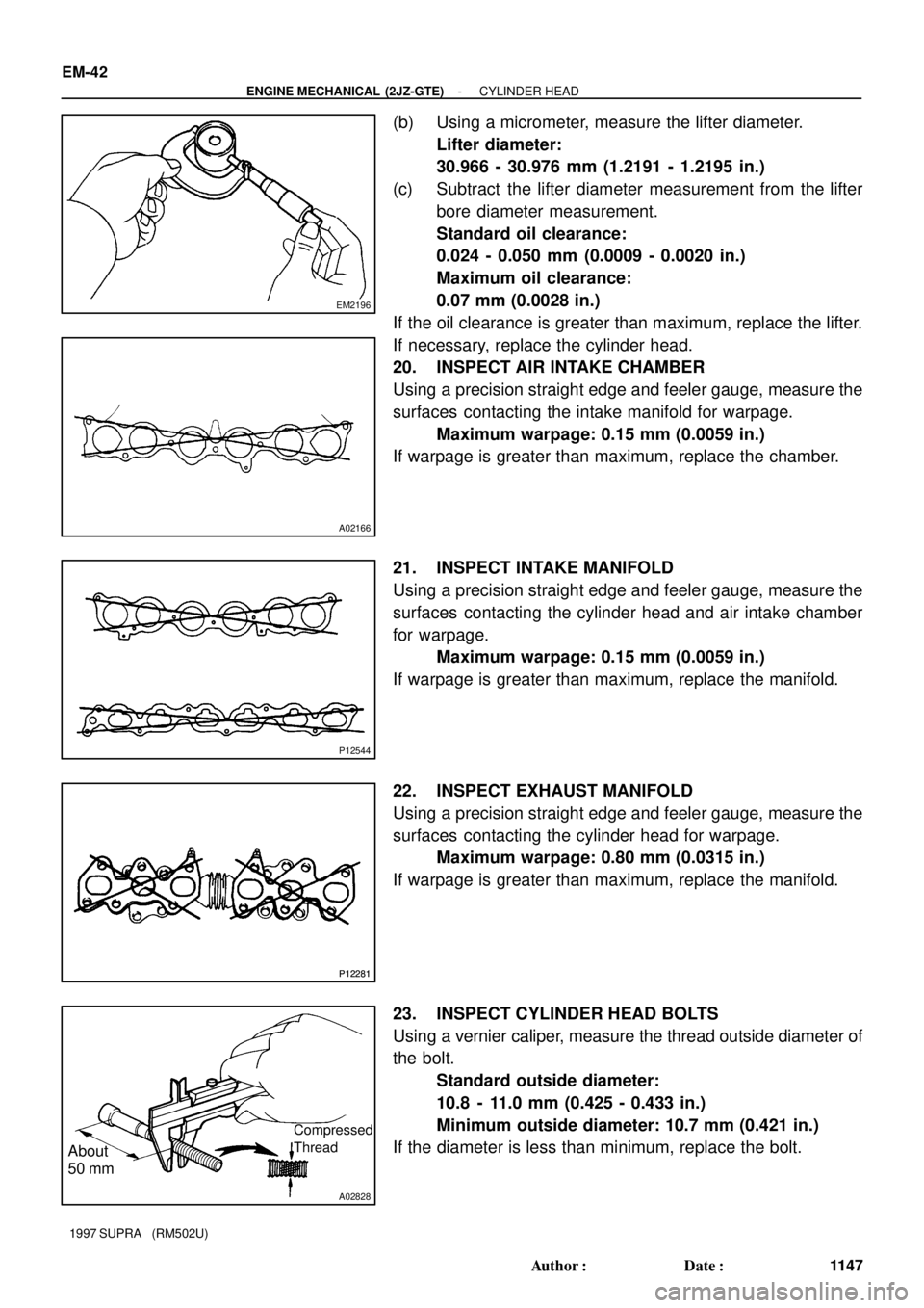
(b) Using a micrometer, measure the lifter diameter.
Lifter diameter:
30.966 - 30.976 mm (1.2191 - 1.2195 in.)
(c) Subtract the lifter diameter measurement from the lifter
bore diameter measurement.
Standard oil clearance:
0.024 - 0.050 mm (0.0009 - 0.0020 in.)
Maximum oil clearance:
0.07 mm (0.0028 in.)
If the oil clearance is greater than maximum, replace the lifter.
If necessary, replace the cylinder head.
20. INSPECT AIR INTAKE CHAMBER
Using a precision straight edge and feeler gauge, measure the
surfaces contacting the intake manifold for warpage.
Maximum warpage: 0.15 mm (0.0059 in.)
If warpage is greater than maximum, replace the chamber.
21. INSPECT INTAKE MANIFOLD
Using a precision straight edge and feeler gauge, measure the
surfaces contacting the cylinder head and air intake chamber
for warpage.
Maximum warpage: 0.15 mm (0.0059 in.)
If warpage is greater than maximum, replace the manifold.
22. INSPECT EXHAUST MANIFOLD
Using a precision straight edge and feeler gauge, measure the
surfaces contacting the cylinder head for warpage.
Maximum warpage: 0.80 mm (0.0315 in.)
If warpage is greater than maximum, replace the manifold.
23. INSPECT CYLINDER HEAD BOLTS
Using a vernier caliper, measure the thread outside diameter of
the bolt.
Standard outside diameter:
10.8 - 11.0 mm (0.425 - 0.433 in.)
Minimum outside diameter: 10.7 mm (0.421 in.)
If the diameter is less than minimum, replace the bolt.
Page 1295 of 1807
EM0AK-02
S00401
SST
P02265
Z16742
SST
P04791
38.5 mm
(1.516 in.) Intake Exhaust
40.5 mm
(1.594 in.)
- ENGINE MECHANICAL (2JZ-GTE)CYLINDER HEAD
EM-43
1148 Author�: Date�:
1997 SUPRA (RM502U)
REPLACEMENT
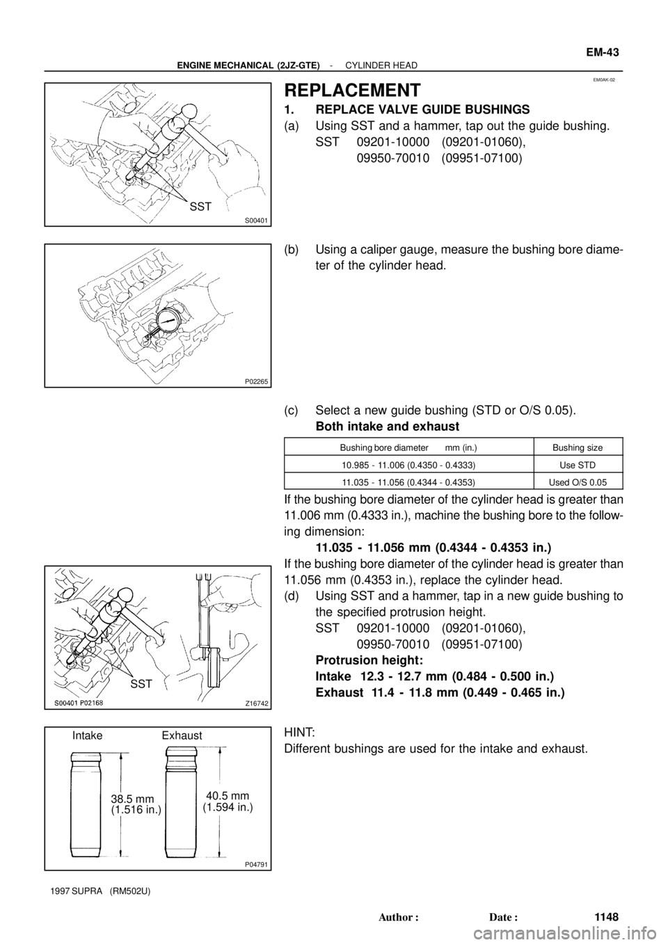
1. REPLACE VALVE GUIDE BUSHINGS
(a) Using SST and a hammer, tap out the guide bushing.
SST 09201-10000 (09201-01060),
09950-70010 (09951-07100)
(b) Using a caliper gauge, measure the bushing bore diame-
ter of the cylinder head.
(c) Select a new guide bushing (STD or O/S 0.05).
Both intake and exhaust
Bushing bore diameter mm (in.)Bushing size
10.985 - 11.006 (0.4350 - 0.4333)Use STD
11.035 - 11.056 (0.4344 - 0.4353)Used O/S 0.05
If the bushing bore diameter of the cylinder head is greater than
11.006 mm (0.4333 in.), machine the bushing bore to the follow-
ing dimension:
11.035 - 11.056 mm (0.4344 - 0.4353 in.)
If the bushing bore diameter of the cylinder head is greater than
11.056 mm (0.4353 in.), replace the cylinder head.
(d) Using SST and a hammer, tap in a new guide bushing to
the specified protrusion height.
SST 09201-10000 (09201-01060),
09950-70010 (09951-07100)
Protrusion height:
Intake 12.3 - 12.7 mm (0.484 - 0.500 in.)
Exhaust 11.4 - 11.8 mm (0.449 - 0.465 in.)
HINT:
Different bushings are used for the intake and exhaust.
Page 1296 of 1807
Z02415
Sharp
6 mm
Reamer EM-44
- ENGINE MECHANICAL (2JZ-GTE)CYLINDER HEAD
1149 Author�: Date�:
1997 SUPRA (RM502U)
(e) Using a sharp 6 mm reamer, ream the guide bushing to
obtain the standard specified clearance (See page
EM-35) between the guide bushing and valve stem.
Page 1297 of 1807
EM0AL-02
P0218510 mm Adhesive Width
2 - 3 mm
Adhesive
Z08040
Protrusion
P12307
(4) (3) (2) (1)
EM0645
Upward
Wide
Narrow
- ENGINE MECHANICAL (2JZ-GTE)CYLINDER HEAD
EM-45
1150 Author�: Date�:
1997 SUPRA (RM502U)
REASSEMBLY
HINT:
�Thoroughly clean all parts to be assembled.
�Before installing the parts, apply fresh engine oil to all slid-
ing and rotating surfaces.
�Replace all gaskets and oil seals with new ones.
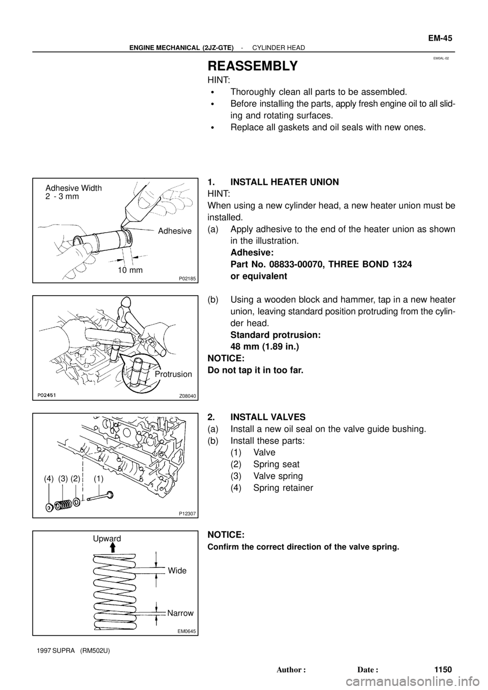
1. INSTALL HEATER UNION
HINT:
When using a new cylinder head, a new heater union must be
installed.
(a) Apply adhesive to the end of the heater union as shown
in the illustration.
Adhesive:
Part No. 08833-00070, THREE BOND 1324
or equivalent
(b) Using a wooden block and hammer, tap in a new heater
union, leaving standard position protruding from the cylin-
der head.
Standard protrusion:
48 mm (1.89 in.)
NOTICE:
Do not tap it in too far.
2. INSTALL VALVES
(a) Install a new oil seal on the valve guide bushing.
(b) Install these parts:
(1) Valve
(2) Spring seat
(3) Valve spring
(4) Spring retainer
NOTICE:
Confirm the correct direction of the valve spring.
Page 1298 of 1807
P12308
SST
P02269
EM-46
- ENGINE MECHANICAL (2JZ-GTE)CYLINDER HEAD
1151 Author�: Date�:
1997 SUPRA (RM502U)
(c) Using SST, compress the valve spring and place the 2
keepers around the valve stem.
SST 09202-70020 (09202-00010)
(d) Using a plastic-faced hammer, lightly tap the valve stem
tip to ensure a proper fit.
3. INSTALL VALVE LIFTERS AND SHIMS
(a) Install the valve lifter and shim.
(b) Check that the valve lifter rotates smoothly by hand.
4. INSTALL EGR COOLER
Install a new gasket and the EGR cooler with the 8 bolts.
Torque: 8.8 N´m (90 kgf´cm, 78 in.´lbf)
5. INSTALL CAMSHAFT POSITION SENSORS
Install the gasket and sensor with the 2 bolts.
Torque: 8.8 N´m (90 kgf´cm, 78 in.´lbf)
6. INSTALL ENGINE HANGERS AND GROUND STRAP
Torque: 39 N´m (400 kgf´cm, 29 ft´lbf)