Page 1443 of 1807
Width
H03208
- SUPPLEMENTAL RESTRAINT SYSTEMSTEERING WHEEL PAD AND SPIRAL CABLE
RS-17
1956 Author�: Date�:
1997 SUPRA (RM502U)
�Covering method using tires:
Plac")
R04211
Inner Diam.
Tires
(3 or More)Width
H03208
- SUPPLEMENTAL RESTRAINT SYSTEMSTEERING WHEEL PAD AND SPIRAL CABLE
RS-17
1956 Author�: Date�:
1997 SUPRA (RM502U)
�Covering method using tires:
Place at least 3 tires without disc wheel on top of the
disc wheel with tire to which the steering wheel pad
is tied.
Tire size: Must exceed the following dimensions-
Width: 185 mm (7.28 in.)
Inner diameter: 360 mm (14.17 in.)
CAUTION:
Do not use tires with disc wheels.
NOTICE:
The tires may be marked by the airbag deployment, so use
the spare tires.
(f) Deploy the airbag.
(1) Connect the SST red clip to the battery positive (+)
terminal and the black clip to the battery negative
(-) terminal.
(2) Check that no one is within 10 m (33 ft) area around
the disc wheel which the steering wheel pad is tied
to.
(3) Press the SST activation switch and deploy the air-
bag.
HINT:
The airbag deploys simultaneously as the LED of the SST ac-
tivation switch lights up.
(g) Dispose of the steering wheel pad (with airbag).
CAUTION:
�The steering wheel pad is very hot when the airbag is
deployed, so leave it alone for at least 30 minutes af-
ter deployment.
�Use gloves and safety glasses when handling a steer-
ing wheel pad with deployed airbag.
�Always wash your hands with water after completing
the operation.
�Do not apply water, etc. to a steering wheel pad with
deployed airbag.
(1) Remove the steering wheel pad from the disc
wheel.
(2) Place the steering wheel pad in a vinyl bag, tie the
end tightly and dispose of it in the same way as oth-
er general parts disposal.
Page 1466 of 1807
FUEL PUMP
1332 Author�: Date�:
1997 SUPRA (RM502U)
(f) Connect the TOYOTA hand-held tester to the DLC3.
(See step 1 in")
Q08242
TOYOTA Hand-Held Tester
DLC3
P12563
Disconnect
Plug SF-6
- SFI (2JZ-GTE)FUEL PUMP
1332 Author�: Date�:
1997 SUPRA (RM502U)
(f) Connect the TOYOTA hand-held tester to the DLC3.
(See step 1 in check fuel pump operation (a) to (e).)
(g) Reconnect the negative (-) terminal cable to the battery.
(h) Turn the ignition switch ON.
(i) Measure the fuel pressure.
Fuel pressure:
226 - 275 kPa (2.3 - 2.8 kgf/cm
2, 33 - 40 psi)
If pressure is high, replace the fuel pressure regulator.
If pressure is low, check the following parts:
(1) Fuel hoses and connections
(2) Fuel pump
(3) Fuel filter
(4) Fuel pressure regulator
(j) Remove the TOYOTA hand-held tester from the
DLC3.
(k) Start the engine.
(l) Disconnect the vacuum sensing hose from the fuel pres-
sure regulator, and plug the hose end.
(m) Measure the fuel pressure at idle.
Fuel pressure:
226 - 275 kPa (2.3 - 2.8 kgf/cm
2, 33 - 40 psi)
(n) Reconnect the vacuum sensing hose to the fuel pressure
regulator.
(o) Measure the fuel pressure at idle.
Fuel pressure:
167 - 216 kPa (1.7 - 2.2 kgf/cm
2, 24 - 31 psi)
If pressure is not as specified, check the vacuum sensing hose
and fuel pressure regulator.
(p) Stop the engine.
(q) Check that the fuel pressure remains as specified for 5
minutes after the engine has stopped.
Fuel pressure:
147 kPa (1.5 kgf/cm
2, 21 psi) or more
If pressure is not as specified, check the fuel pump, pressure
regulator and/or injectors.
(r) After checking fuel pressure, disconnect the negative (-)
terminal cable from the battery and carefully remove the
SST to prevent gasoline from splashing.
SST 09268-45012
(s) Reinstall the fuel inlet hose to the fuel filter with 2 new gas-
kets and the union bolt.
Torque: 29 N´m (300 kgf´cm, 22 ft´lbf)
(t) Reconnect the negative (-) terminal cable to the battery.
(u) Check for fuel leaks.
3. TAKE OUT FLOOR CARPET
4. REMOVE SPARE WHEEL COVER
5. REMOVE SPARE WHEEL
6. REMOVE SERVICE HOLE COVER
7. DISCONNECT FUEL PUMP & SENDER GAUGE CON-
NECTOR
Page 1467 of 1807
FUEL PUMP
SF-7
1333 Author�: Date�:
1997 SUPRA (RM502U)
8. INSPECT FUEL PUMP RESISTANCE
Using an ohmmeter, measure the resistance between termina")
B01419
Ohmmeter4
5
B01429
4
5
Battery
- SFI (2JZ-GTE)FUEL PUMP
SF-7
1333 Author�: Date�:
1997 SUPRA (RM502U)
8. INSPECT FUEL PUMP RESISTANCE
Using an ohmmeter, measure the resistance between terminals
4 and 5.
Resistance: 0.1 - 3.0 W at 20°C (68°F)
If the resistance is not as specified, replace the fuel pump, lead
wire or fuel pump bracket.
9. INSPECT FUEL PUMP OPERATION
Connect a tester lead from terminal 4 of the connector to the
positive (+) terminal of the battery; connect another tester lead
from terminal 5 of the connector to the negative (-) terminal of
the battery.
NOTICE:
�These tests must be performed quickly (within 10 se-
conds) to prevent the coil from burning out.
�Keep the fuel pump as far away from the battery as
possible.
�Always connect or disconnect at the battery.
If operation is not as specified, replace the fuel pump, lead wire
or fuel pump bracket.
10. RECONNECT FUEL PUMP & SENDER GAUGE CON-
NECTOR
11. INSTALL SERVICE HOLE COVER
12. INSTALL SPARE WHEEL
13. INSTALL SPARE WHEEL COVER
14. INSTALL FLOOR CARPET
Page 1468 of 1807
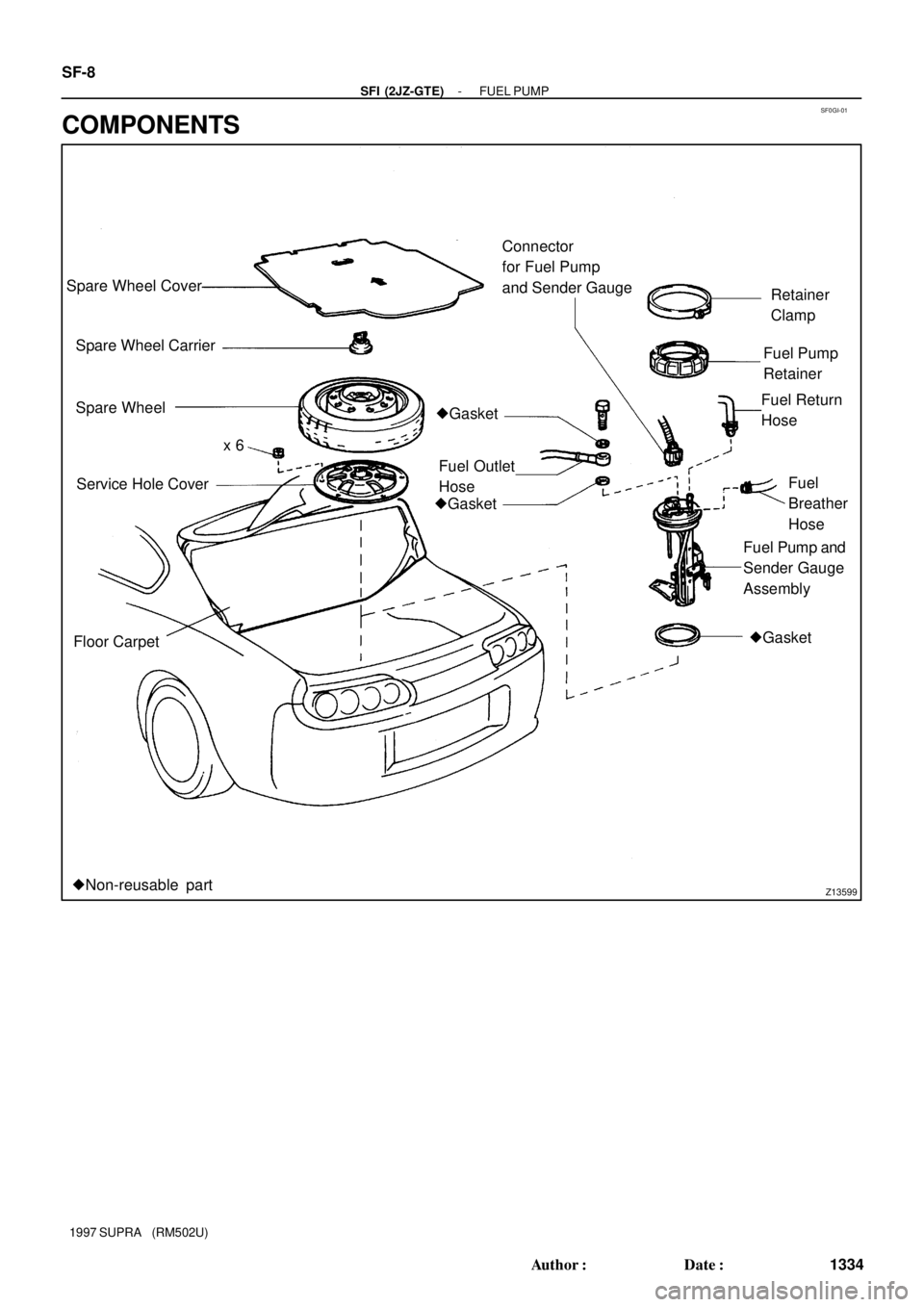
SF0GI-01
Z13599
Spare Wheel Cover
Spare Wheel Carrier
Spare Wheel
Service Hole Cover
Floor CarpetConnector
for Fuel Pump
and Sender Gauge
�Gasket
Fuel Outlet
HoseFuel Return
Hose
�GasketRetainer
Clamp
�GasketFuel
Breather
Hose
Fuel Pump and
Sender Gauge
Assembly
�Non-reusable partFuel Pump
Retainer
x 6 SF-8
- SFI (2JZ-GTE)FUEL PUMP
1334 Author�: Date�:
1997 SUPRA (RM502U)
COMPONENTS
Page 1470 of 1807
SF19Z-01
P11357
(1) (2)
(3) (4)
P11280
SST
Rib
P12033
Fuel Return
Hose SF-10
- SFI (2JZ-GTE)FUEL PUMP
1336 Author�: Date�:
1997 SUPRA (RM502U)
REMOVAL
CAUTION:
Do not smoke or work near an open flame when working on
the fuel pump.
1. TAKE OUT FLOOR CARPET
2. REMOVE SPARE WHEEL COVER
3. REMOVE SPARE WHEEL
4. REMOVE SERVICE HOLE COVER
5. REMOVE FUEL PUMP AND SENDER GAUGE
ASSEMBLY
(a) Disconnect the connector and hoses from the fuel pump
bracket:
(1) Fuel pump connector
(2) Fuel outlet hose
Remove the union bolt and 2 gaskets, and discon-
nect the outlet hose.
(3) Fuel return hose
(4) Fuel breather hose
(b) Remove the retainer clamp.
(c) Using SST, loosen the retainer.
SST 09808-14010
(d) Remove the retainer, and disconnect the fuel pump and
sender gauge assembly from the fuel tank.
(e) Disconnect the fuel return hose from the return port of the
fuel pump bracket.
(f) Remove the fuel pump, sender gauge assembly and gas-
ket.
Page 1473 of 1807
SF-14
- SFI (2JZ-GTE)FUEL PUMP
1340 Author�: Date�:
1997 SUPRA (RM502U)
�Fuel return hose
�Fuel breather hose
2. INSTALL SERVICE HOLE COVER
3. INSTALL SPARE WHEEL
4. INSTALL SPARE WHEEL COVER
5. INSTALL FLOOR CARPET
6. CHECK FOR FUEL LEAKS