Page 2887 of 3342

�When ABS warning light illuminates, read and record
trouble code indicated by ABS warning light.
B: CHECK LIST FOR INTERVIEW
Check the following items about the vehicle’s state.
1. THE STATE OF THE ABS WARNING LIGHT
ABS warning light
comes on.�Always
�Sometimes
�Only once
�Does not come on
�When /how long does it come on?:
Ignition key position�LOCK
�ACC
�ON (before starting engine)
�START
�On after starting (Engine is running)
�On after starting (Engine is stop)
Timing�Immediately after ignition is ON.
�Immediately after ignition starts.
�When advancing km/h to km/h
MPH to MPH
�While traveling at a constant speed km/h MPH
�When decelerating km/h to km/h
MPH to MPH
�When turning to right Steering angle : deg
Steering time : sec
�When turning to left Steering angle : deg
Steering time : sec
�When moving other electrical parts
�Parts name :
�Operating condition :
2. SYMPTOMS
ABS operating
condition�Performs no work.
�Operates only when abruptly applying brakes. Vehicle speed : km/h
MPH
�How to step on brake pedal :
a) Operating time :sec
b) Operating noise :�Produce /�Does not produce
�What kind of noise?�Knock
�Gong gong
�Bong
�Buzz
�Gong gong buzz
�Others :
c) Reaction force of brake pedal
�Stick
�Press down once with a clunk
�Press and released
�Others :
11
4-4dBRAKES [ABS 5.3i TYPE]
6. Diagnostics Chart for On-board Diagnosis System
Page 2890 of 3342

for at least one minute.
B4M0082D
D: TROUBL")
C: INSPECTION MODE
Reproduce the condition under which the problem has
occurred as much as possible.
Drive the vehicle at a speed more than 40 km/h (25 MPH)
for at least one minute.
B4M0082D
D: TROUBLE CODES
When on-board diagnosis of the ABS control module
detects a problem, the information (up to a maximum of
three) will be stored in the EEP ROM as a trouble code.
When there are more than three, the most recent three will
be stored. (Stored codes will stay in memory until they are
cleared.)
1. CALLING UP A TROUBLE CODE
1) Take out diagnosis connector from side of driver’s seat
heater unit.
2) Turn ignition switch OFF.
3) Connect diagnosis connector terminal 6 to diagnosis
terminal.
4) Turn ignition switch ON.
5) ABS warning light is set in the diagnostic mode and
blinks to identify trouble code.
6) After the start code (11) is shown, the trouble codes will
be shown in order of the last information first.
These repeat for a maximum of 5 minutes.
NOTE:
When there are no trouble codes in memory, only the start
code (11) is shown.
B4M0232A
14
4-4dBRAKES [ABS 5.3i TYPE]
6. Diagnostics Chart for On-board Diagnosis System
Page 2892 of 3342
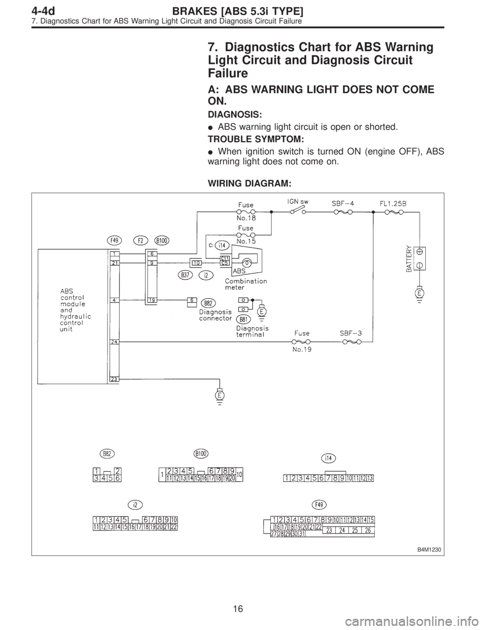
7. Diagnostics Chart for ABS Warning
Light Circuit and Diagnosis Circuit
Failure
A: ABS WARNING LIGHT DOES NOT COME
ON.
DIAGNOSIS:
�ABS warning light circuit is open or shorted.
TROUBLE SYMPTOM:
�When ignition switch is turned ON (engine OFF), ABS
warning light does not come on.
WIRING DIAGRAM:
B4M1230
16
4-4dBRAKES [ABS 5.3i TYPE]
7. Diagnostics Chart for ABS Warning Light Circuit and Diagnosis Circuit Failure
Page 2893 of 3342
7A1CHECK IF OTHER WARNING LIGHTS
TURN ON.
Turn ignition switch to ON (engine OFF).
: Do other warning lights turn on?
: Go to step7A2.
: Repair combination meter.
7A2
CHECK ABS WARNING LIGHT BULB.
1) Turn ignition switch to OFF.
2) Remove combination meter.
3) Remove ABS warning light bulb from combination
meter.
: Is ABS warning light bulb OK?
: Go to step7A3.
: Replace ABS warning light bulb.
B4M1273A
7A3CHECK BATTERY SHORT OF ABS
WARNING LIGHT HARNESS.
1) Disconnect connector (B100) from connector (F2).
2) Measure voltage between connector (B100) and chas-
sis ground.
Connector & terminal
(B100) No. 9 (+) — Chassis ground (�):
: Is the voltage less than 3 V?
: Go to step7A4.
: Repair warning light harness.
17
4-4dBRAKES [ABS 5.3i TYPE]
7. Diagnostics Chart for ABS Warning Light Circuit and Diagnosis Circuit Failure
Page 2894 of 3342
B4M1273A
7A4CHECK BATTERY SHORT OF ABS
WARNING LIGHT HARNESS.
1) Turn ignition switch to ON.
2) Measure voltage between connector (B100) and chas-
sis ground.
Connector & terminal
(B100) No. 9 (+)—Chassis ground (�):
: Is voltage less than 3 V?
: Go to step7A5.
: Repair warning light harness.
B4M1273A
7A5
CHECK WIRING HARNESS.
1) Turn ignition switch to OFF.
2) Install ABS warning light bulb from combination meter.
3) Install combination meter.
4) Turn ignition switch to ON.
5) Measure voltage between connector (B100) and chas-
sis ground.
Connector & terminal
(B100) No. 9 (+)—Chassis ground (�):
: Is voltage between 10 V and 15 V?
: Go to step7A6.
: Repair wiring harness.
18
4-4dBRAKES [ABS 5.3i TYPE]
7. Diagnostics Chart for ABS Warning Light Circuit and Diagnosis Circuit Failure
Page 2895 of 3342
B4M1274A
7A6CHECK BATTERY SHORT OF ABS
WARNING LIGHT HARNESS.
1) Turn ignition switch to OFF.
2) Measure voltage between connector (F2) and chassis
ground.
Connector & terminal
(F2) No. 9 (+)—Chassis ground (�):
: Is the voltage less than 3 V?
: Go to step7A7.
: Repair wiring harness.
B4M1274A
7A7CHECK BATTERY SHORT OF ABS
WARNING LIGHT HARNESS.
1) Turn ignition switch to ON.
2) Measure voltage between connector (F2) and chassis
ground.
Connector & terminal
(F2) No. 9 (+)—Chassis ground (�):
: Is voltage less than 3 V?
: Go to step7A8.
: Repair wiring harness.
B4M1243A
7A8CHECK GROUND CIRCUIT OF
ABSCM&H/U.
Measure resistance between ABSCM&H/U and chassis
ground.
Connector & terminal
(F49) No. 23—GND:
: Is the resistance less than 0.5Ω?
: Go to step7A9.
: Repair ABSCM&H/U ground harness.
19
4-4dBRAKES [ABS 5.3i TYPE]
7. Diagnostics Chart for ABS Warning Light Circuit and Diagnosis Circuit Failure
Page 2896 of 3342
B4M1275A
7A9
CHECK WIRING HARNESS.
Measure resistance between connector (F2) and chassis
ground.
Connector & terminal
(F2) No. 9—Chassis ground:
: Is the resistance less than 0.5Ω?
: Go to step7A10.
: Repair harness/connector.
7A10CHECK POOR CONTACT IN CONNEC-
TORS.
Turn ignition switch to OFF.
: Is there poor contact in connectors between
combination meter and ABSCM&H/U?
to FOREWORD [T3C1].>
: Repair connector.
: Replace ABSCM&H/U.
20
4-4dBRAKES [ABS 5.3i TYPE]
7. Diagnostics Chart for ABS Warning Light Circuit and Diagnosis Circuit Failure
Page 2898 of 3342

7B1CHECK INSTALLATION OF ABSCM&H/U
CONNECTOR.
Turn ignition switch to OFF.
: Is ABSCM&H/U connector inserted into
ABSCM until the clamp locks onto it?
: Go to step7B2.
: Insert ABSCM&H/U connector into ABSCM&H/U
until the clamp locks onto it.
B4M0800A
7B2
CHECK DIAGNOSIS TERMINAL.
Measure resistance between diagnosis terminals (B81)
and chassis ground.
: Terminals
Diagnosis terminal (A)—Chassis ground:
Diagnosis terminal (B)—Chassis ground:
Is the resistance less than 0.5Ω?
: Go to step7B3.
: Repair diagnosis terminal harness.
B4M1233A
7B3
CHECK DIAGNOSIS LINE.
1) Turn ignition switch to OFF.
2) Connect diagnosis terminal to diagnosis connector
(B82) No. 6.
3) Disconnect connector from ABSCM&H/U.
4) Measure resistance between ABSCM&H/U connector
and chassis ground.
: Connector & terminal
(F49) No. 4—Chassis ground:
Is the resistance less than 0.5Ω?
: Go to step7B4.
: Repair harness connector between ABSCM&H/U
and diagnosis connector.
22
4-4dBRAKES [ABS 5.3i TYPE]
7. Diagnostics Chart for ABS Warning Light Circuit and Diagnosis Circuit Failure
.
: Do other warning lights turn on?
: Go to step7A2.
: Repair combination meter.
7A2
CHECK ABS WARNING LIGHT BULB.
1)")
 Turn ignition switch to ON.
2) Measure voltage between connector (B100) and chas-
sis ground.
Connector & terminal
(B100) No. 9 (+)—C")
 Turn ignition switch to OFF.
2) Measure voltage between connector (F2) and chassis
ground.
Connector & terminal
(F2) No. 9 (+)—Chassi")
 and chassis
ground.
Connector & terminal
(F2) No. 9—Chassis ground:
: Is the resistance less than 0.5Ω?
: Go to step7A1")