Page 3323 of 3342

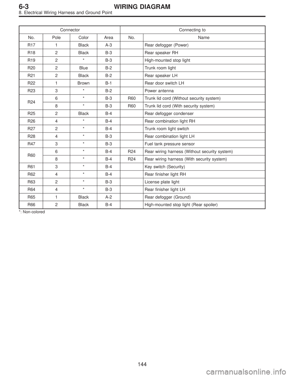
Connector Connecting to
No. Pole Color Area No. Name
R17 1 Black A-3 Rear defogger (Power)
R18 2 Black B-3 Rear speaker RH
R19 2 * B-3 High-mounted stop light
R20 2 Blue B-2 Trunk room light
R21 2 Black B-2 Rear speaker LH
R22 1 Brown B-1 Rear door switch LH
R23 3 * B-2 Power antenna
R246 * B-3 R60 Trunk lid cord (Without security system)
8 * B-3 R60 Trunk lid cord (With security system)
R25 2 Black B-4 Rear defogger condenser
R26 4 * B-4 Rear combination light RH
R27 2 * B-4 Trunk room light switch
R28 4 * B-3 Rear combination light LH
R47 3 * B-3 Fuel tank pressure sensor
R606 * B-4 R24 Rear wiring harness (Without security system)
8 * B-4 R24 Rear wiring harness (With security system)
R61 3 * B-4 Key switch (Security)
R62 4 * B-4 Rear finisher light RH
R63 2 * B-3 License plate light
R64 4 * B-3 Rear finisher light LH
R65 1 Black A-2 Rear defogger (Ground)
R66 2 Black B-4 High-mounted stop light (Rear spoiler)
*: Non-colored
144
6-3WIRING DIAGRAM
8. Electrical Wiring Harness and Ground Point
Page 3324 of 3342
9. REAR END WIRING HARNESS AND GROUND POINT OF WAGON
�LHD model
B6M0694A
145
6-3WIRING DIAGRAM
8. Electrical Wiring Harness and Ground Point
Page 3325 of 3342

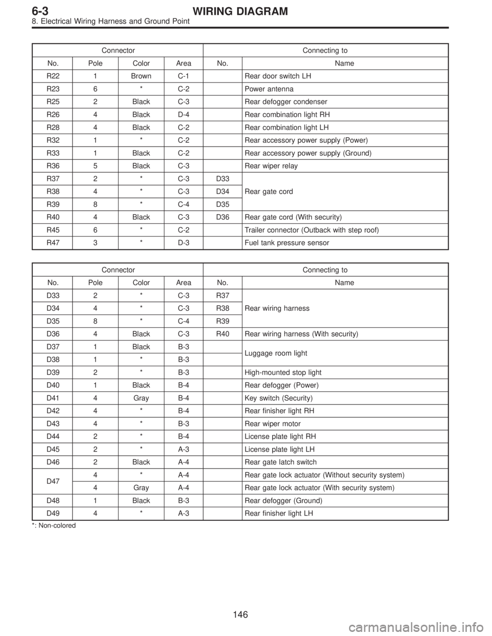
Connector Connecting to
No. Pole Color Area No. Name
R22 1 Brown C-1 Rear door switch LH
R23 6 * C-2 Power antenna
R25 2 Black C-3 Rear defogger condenser
R26 4 Black D-4 Rear combination light RH
R28 4 Black C-2 Rear combination light LH
R32 1 * C-2 Rear accessory power supply (Power)
R33 1 Black C-2 Rear accessory power supply (Ground)
R36 5 Black C-3 Rear wiper relay
R37 2 * C-3 D33
Rear gate cord R38 4 * C-3 D34
R39 8 * C-4 D35
R40 4 Black C-3 D36 Rear gate cord (With security)
R45 6 * C-2 Trailer connector (Outback with step roof)
R47 3 * D-3 Fuel tank pressure sensor
Connector Connecting to
No. Pole Color Area No. Name
D33 2 * C-3 R37
Rear wiring harness D34 4 * C-3 R38
D35 8 * C-4 R39
D36 4 Black C-3 R40 Rear wiring harness (With security)
D37 1 Black B-3
Luggage room light
D38 1 * B-3
D39 2 * B-3 High-mounted stop light
D40 1 Black B-4 Rear defogger (Power)
D41 4 Gray B-4 Key switch (Security)
D42 4 * B-4 Rear finisher light RH
D43 4 * B-3 Rear wiper motor
D44 2 * B-4 License plate light RH
D45 2 * A-3 License plate light LH
D46 2 Black A-4 Rear gate latch switch
D474 * A-4 Rear gate lock actuator (Without security system)
4 Gray A-4 Rear gate lock actuator (With security system)
D48 1 Black B-3 Rear defogger (Ground)
D49 4 * A-3 Rear finisher light LH
*: Non-colored
146
6-3WIRING DIAGRAM
8. Electrical Wiring Harness and Ground Point
Page 3326 of 3342
9. REAR END WIRING HARNESS AND GROUND POINT OF WAGON
�RHD model
EPA0109
147
6-3WIRING DIAGRAM
8. Electrical Wiring Harness and Ground Point
Page 3327 of 3342
Connector Connecting to
No. Pole Color Area No. Name
R22 1 Brown C-1 Rear door switch LH
R23 6 * C-2 Power antenna
R25 2 Black C-3 Rear defogger condenser
R26 4 Black D-4 Rear combination light RH
R28 4 Black C-2 Rear combination light LH
R36 5 Black C-3 Rear wiper relay
R37 2 * C-3 D33
Rear gate cord R38 4 * C-3 D34
R39 8 * C-4 D35
R47 3 * D-3 Fuel tank pressure sensor
Connector Connecting to
No. Pole Color Area No. Name
D33 2 * C-3 R37
Rear wiring harness D34 4 * C-3 R38
D35 8 * C-4 R39
D37 1 Black B-3
Luggage room light
D38 1 * B-3
D39 2 * B-3 High-mounted stop light
D40 1 Black B-4 Rear defogger (Power)
D42 4 * B-4 Rear finisher light RH
D43 4 * B-3 Rear wiper motor
D44 2 * B-4 License plate light RH
D45 2 * A-3 License plate light LH
D46 2 Black A-4 Rear gate latch switch
D47 4 * A-4 Rear gate lock actuator
D48 1 Black B-3 Rear defogger (Ground)
D49 4 * A-3 Rear finisher light LH
*: Non-colored
148
6-3WIRING DIAGRAM
8. Electrical Wiring Harness and Ground Point
Page 3329 of 3342

How to use this manual
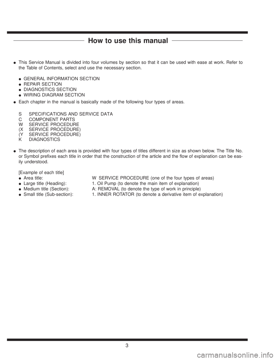
�This Service Manual is divided into four volumes by section so that it can be used with ease at work. Refer to
the Table of Contents, select and use the necessary section.
�GENERAL INFORMATION SECTION
�REPAIR SECTION
�DIAGNOSTICS SECTION
�WIRING DIAGRAM SECTION
�Each chapter in the manual is basically made of the following four types of areas.
S SPECIFICATIONS AND SERVICE DATA
C COMPONENT PARTS
W SERVICE PROCEDURE
(X SERVICE PROCEDURE)
(Y SERVICE PROCEDURE)
K DIAGNOSTICS
�The description of each area is provided with four types of titles different in size as shown below. The Title No.
or Symbol prefixes each title in order that the construction of the article and the flow of explanation can be eas-
ily understood.
[Example of each title]
�Area title: W SERVICE PROCEDURE (one of the four types of areas)
�Large title (Heading): 1. Oil Pump (to denote the main item of explanation)
�Medium title (Section): A: REMOVAL (to denote the type of work in principle)
�Small title (Sub-section): 1. INNER ROTATOR (to denote a derivative item of explanation)
3
Page 3333 of 3342
2. How to Use this Manual
�This Service Manual is divided into four volumes by section so that it can be used with ease at work.
Refer to the Table of Contents, select and use the necessary section.
�GENERAL INFORMATION SECTION
�REPAIR SECTION
�DIAGNOSTICS SECTION
�WIRING DIAGRAM SECTION
�The description of each area is provided with four types of titles different in size as shown below. The
Title No. or Symbol prefixes each title in order that the construction of the article and the flow of explana-
tion can be easily understood.
[Example of each title]
�Area title: T. DIAGNOSTICS
�Large title (Heading): 1. Diagnostics Chart with Select Monitor (to denote the main item of explanation.)
�Medium title (Section): A: BASIC DIAGNOSTICS CHART (to denote the type of work in principle.)
�Small title (Sub-section): 1. CHECK INPUT SIGNAL FOR ECM (to denote a derivative item of explanation.)
3
[T200] FOREWORDFOREWORD
2. How to Use this Manual