Page 2738 of 3342
DIAGNOSIS:
�Faulty ABS sensor (Broken wire, input voltage too high)
�Faulty harness connector
TROUBLE SYMPTOM:
�ABS does not operate.
10H1.Check output of ABS sensor using select
monitor.
�
10H2.Check ABS sensor mechanical trouble.
10H3.Check poor contact in connector between
ABSCM and ABS sensor.
10H4.Check ABSCM.
10H5.Check resistance of ABS sensor.
10H6.Check battery short of ABS sensor.
10H7.Check harness connector between ABSCM
and ABS sensor.
10H8.Check battery short of harness.
10H9.Check ABS sensor mechanical trouble.
10H10.Check poor contact in connector between
ABSCM and ABS sensor.
10H11.Check ABSCM.
�
�
�
�
�
�
�
�
�
133
4-4cBRAKES [ABS 5.3 TYPE]
10. Diagnostics Chart with Select Monitor
Page 2742 of 3342

B4M0806B
B4M1036A
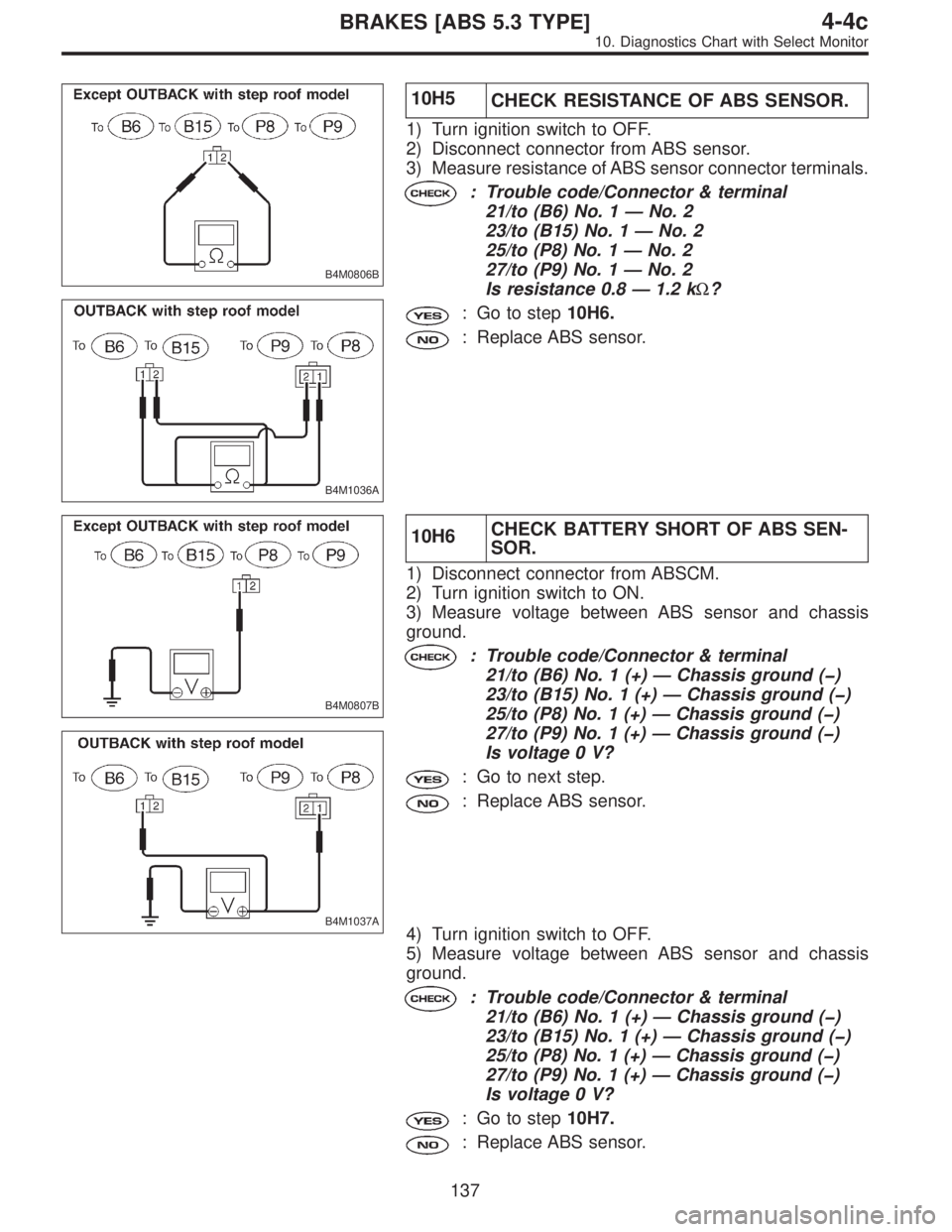
10H5
CHECK RESISTANCE OF ABS SENSOR.
1) Turn ignition switch to OFF.
2) Disconnect connector from ABS sensor.
3) Measure resistance of ABS sensor connector terminals.
: Trouble code/Connector & terminal
21/to (B6) No. 1—No. 2
23/to (B15) No. 1—No. 2
25/to (P8) No. 1—No. 2
27/to (P9) No. 1—No. 2
Is resistance 0.8—1.2 kΩ?
: Go to step10H6.
: Replace ABS sensor.
B4M0807B
B4M1037A
10H6CHECK BATTERY SHORT OF ABS SEN-
SOR.
1) Disconnect connector from ABSCM.
2) Turn ignition switch to ON.
3) Measure voltage between ABS sensor and chassis
ground.
: Trouble code/Connector & terminal
21/to (B6) No. 1 (+)—Chassis ground (�)
23/to (B15) No. 1 (+)—Chassis ground (�)
25/to (P8) No. 1 (+)—Chassis ground (�)
27/to (P9) No. 1 (+)—Chassis ground (�)
Is voltage 0 V?
: Go to next step.
: Replace ABS sensor.
4) Turn ignition switch to OFF.
5) Measure voltage between ABS sensor and chassis
ground.
: Trouble code/Connector & terminal
21/to (B6) No. 1 (+)—Chassis ground (�)
23/to (B15) No. 1 (+)—Chassis ground (�)
25/to (P8) No. 1 (+)—Chassis ground (�)
27/to (P9) No. 1 (+)—Chassis ground (�)
Is voltage 0 V?
: Go to step10H7.
: Replace ABS sensor.
137
4-4cBRAKES [ABS 5.3 TYPE]
10. Diagnostics Chart with Select Monitor
Page 2743 of 3342

B4M0809A
10H7CHECK HARNESS CONNECTOR
BETWEEN ABSCM AND ABS SENSOR.
1) Connect connector to ABS sensor.
2) Measure resistance between ABSCM connector termi-
nals.
: Trouble code/Connector & terminal
21/(F49) No. 14—No. 15
23/(F49) No. 49—No. 19
25/(F49) No. 18—No. 46
27/(F49) No. 16—No. 17
Is resistance 0.8—1.2 kΩ?
: Go to step10H8.
: Repair harness connector between ABSCM and
ABS sensor.
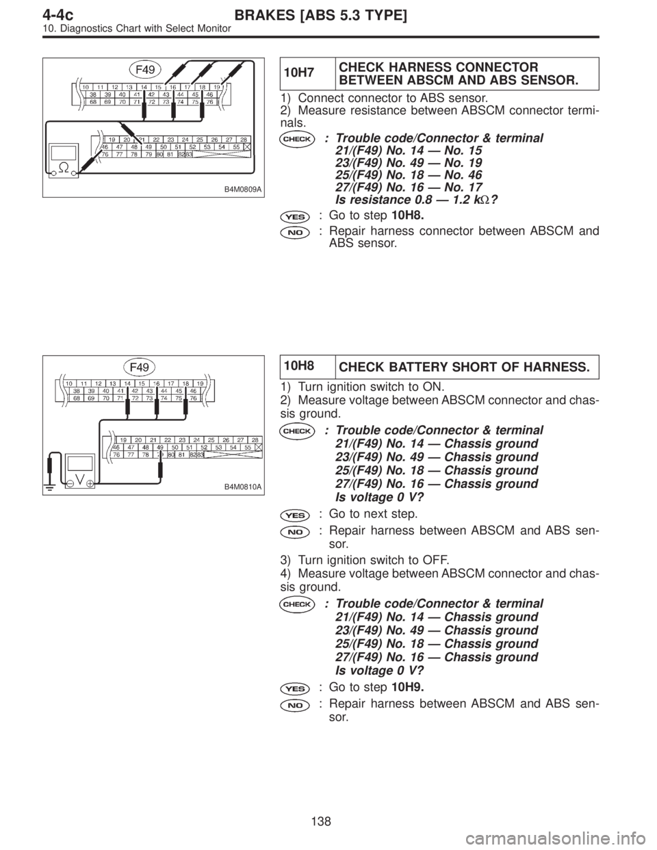
B4M0810A
10H8
CHECK BATTERY SHORT OF HARNESS.
1) Turn ignition switch to ON.
2) Measure voltage between ABSCM connector and chas-
sis ground.
: Trouble code/Connector & terminal
21/(F49) No. 14—Chassis ground
23/(F49) No. 49—Chassis ground
25/(F49) No. 18—Chassis ground
27/(F49) No. 16—Chassis ground
Is voltage 0 V?
: Go to next step.
: Repair harness between ABSCM and ABS sen-
sor.
3) Turn ignition switch to OFF.
4) Measure voltage between ABSCM connector and chas-
sis ground.
: Trouble code/Connector & terminal
21/(F49) No. 14—Chassis ground
23/(F49) No. 49—Chassis ground
25/(F49) No. 18—Chassis ground
27/(F49) No. 16—Chassis ground
Is voltage 0 V?
: Go to step10H9.
: Repair harness between ABSCM and ABS sen-
sor.
138
4-4cBRAKES [ABS 5.3 TYPE]
10. Diagnostics Chart with Select Monitor
Page 2763 of 3342
DIAGNOSIS:
�Faulty harness/connector
�Faulty inlet solenoid valve in hydraulic unit
TROUBLE SYMPTOM:
�ABS does not operate.
10Q1.Check freeze frame data.
�
�
�
10Q2.Check the condition when the trouble
occurred.
10Q3.Check resistance of solenoid valve.
10Q4.Check ground short of solenoid valve.
10Q5.Check ground short of harness.
10Q6.Check harness connector between ABSCM
and hydraulic unit.
10Q7.Check poor contact in connector between
ABSCM and hydraulic unit.
10Q8.Check ABSCM.
10Q9.Check battery short of solenoid valve.
10Q10.Check battery short of harness.
10Q11.Check resistance of solenoid valve.
10Q12.Check ground short of solenoid valve.
Continues to next page.
�
�
�
�
�
�
�
�
�
�
158
4-4cBRAKES [ABS 5.3 TYPE]
10. Diagnostics Chart with Select Monitor
Page 2764 of 3342
From the former page.
10Q13.
Check battery short of solenoid valve.
10Q14.Check battery short of harness.
10Q15.Check ground short of harness.
10Q16.Check harness connector between ABSCM
and hydraulic unit.
10Q17.Check poor contact in connector between
ABSCM and hydraulic unit.
10Q18.Check ABSCM.
�
�
�
�
�
�
159
4-4cBRAKES [ABS 5.3 TYPE]
10. Diagnostics Chart with Select Monitor
Page 2769 of 3342

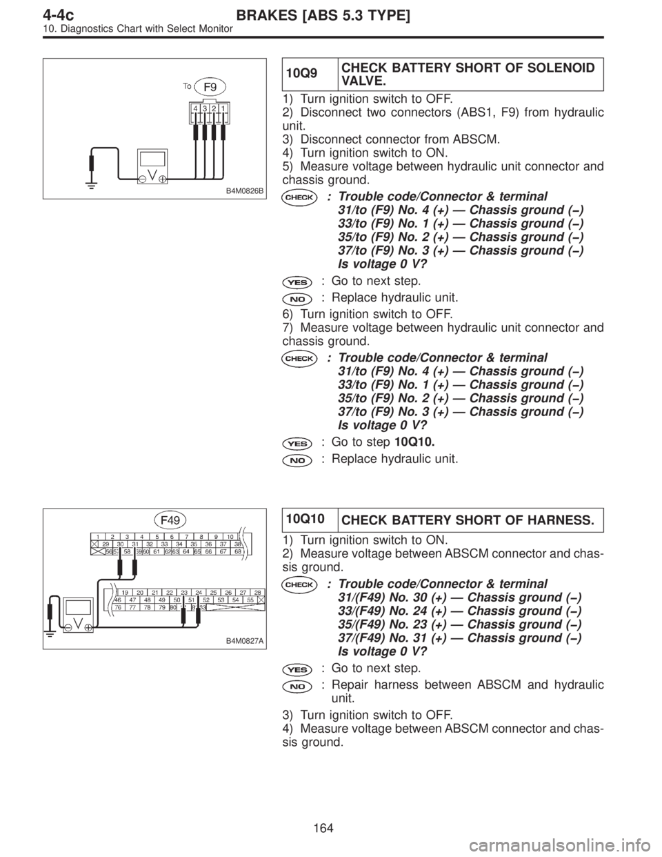
B4M0826B
10Q9CHECK BATTERY SHORT OF SOLENOID
VA LV E .
1) Turn ignition switch to OFF.
2) Disconnect two connectors (ABS1, F9) from hydraulic
unit.
3) Disconnect connector from ABSCM.
4) Turn ignition switch to ON.
5) Measure voltage between hydraulic unit connector and
chassis ground.
: Trouble code/Connector & terminal
31/to (F9) No. 4 (+)—Chassis ground (�)
33/to (F9) No. 1 (+)—Chassis ground (�)
35/to (F9) No. 2 (+)—Chassis ground (�)
37/to (F9) No. 3 (+)—Chassis ground (�)
Is voltage 0 V?
: Go to next step.
: Replace hydraulic unit.
6) Turn ignition switch to OFF.
7) Measure voltage between hydraulic unit connector and
chassis ground.
: Trouble code/Connector & terminal
31/to (F9) No. 4 (+)—Chassis ground (�)
33/to (F9) No. 1 (+)—Chassis ground (�)
35/to (F9) No. 2 (+)—Chassis ground (�)
37/to (F9) No. 3 (+)—Chassis ground (�)
Is voltage 0 V?
: Go to step10Q10.
: Replace hydraulic unit.
B4M0827A
10Q10
CHECK BATTERY SHORT OF HARNESS.
1) Turn ignition switch to ON.
2) Measure voltage between ABSCM connector and chas-
sis ground.
: Trouble code/Connector & terminal
31/(F49) No. 30 (+)—Chassis ground (�)
33/(F49) No. 24 (+)—Chassis ground (�)
35/(F49) No. 23 (+)—Chassis ground (�)
37/(F49) No. 31 (+)—Chassis ground (�)
Is voltage 0 V?
: Go to next step.
: Repair harness between ABSCM and hydraulic
unit.
3) Turn ignition switch to OFF.
4) Measure voltage between ABSCM connector and chas-
sis ground.
164
4-4cBRAKES [ABS 5.3 TYPE]
10. Diagnostics Chart with Select Monitor
Page 2771 of 3342

B4M0826B
10Q13CHECK BATTERY SHORT OF SOLENOID
VA LV E .
1) Disconnect connector from ABSCM.
2) Turn ignition switch to ON.
3) Measure voltage between hydraulic unit connector and
chassis ground.
: Trouble code/Connector & terminal
31/to (F9) No. 4 (+)—Chassis ground (�)
33/to (F9) No. 1 (+)—Chassis ground (�)
35/to (F9) No. 2 (+)—Chassis ground (�)
37/to (F9) No. 3 (+)—Chassis ground (�)
Is voltage 0 V?
: Go to next step.
: Replace hydraulic unit.
4) Turn ignition switch to OFF.
5) Measure voltage between hydraulic unit connector and
chassis ground.
: Trouble code/Connector & terminal
31/to (F9) No. 4 (+)—Chassis ground (�)
33/to (F9) No. 1 (+)—Chassis ground (�)
35/to (F9) No. 2 (+)—Chassis ground (�)
37/to (F9) No. 3 (+)—Chassis ground (�)
Is voltage 0 V?
: Go to step10Q14.
: Replace hydraulic unit.
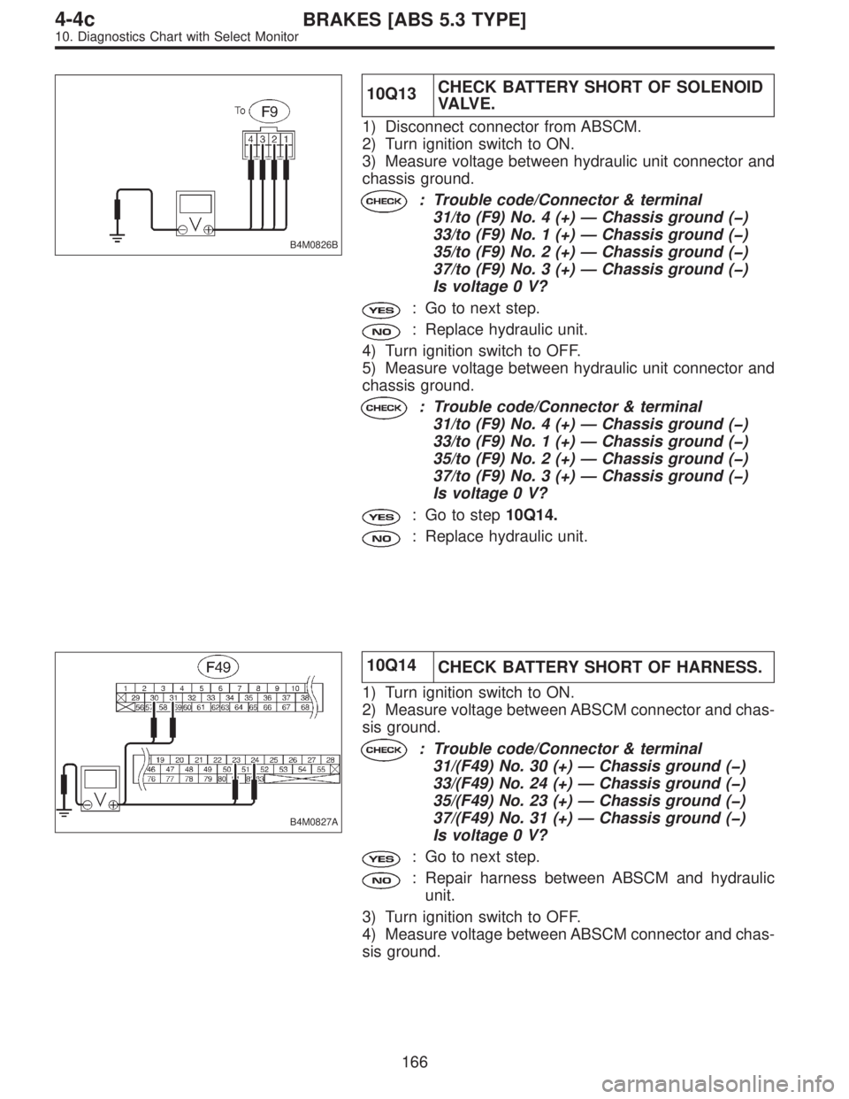
B4M0827A
10Q14
CHECK BATTERY SHORT OF HARNESS.
1) Turn ignition switch to ON.
2) Measure voltage between ABSCM connector and chas-
sis ground.
: Trouble code/Connector & terminal
31/(F49) No. 30 (+)—Chassis ground (�)
33/(F49) No. 24 (+)—Chassis ground (�)
35/(F49) No. 23 (+)—Chassis ground (�)
37/(F49) No. 31 (+)—Chassis ground (�)
Is voltage 0 V?
: Go to next step.
: Repair harness between ABSCM and hydraulic
unit.
3) Turn ignition switch to OFF.
4) Measure voltage between ABSCM connector and chas-
sis ground.
166
4-4cBRAKES [ABS 5.3 TYPE]
10. Diagnostics Chart with Select Monitor
Page 2775 of 3342
DIAGNOSIS:
�Faulty harness/connector
�Faulty outlet solenoid valve in hydraulic unit
TROUBLE SYMPTOM:
�ABS does not operate.
10U1.Check freeze frame data.
�
�
�
10U2.Check the condition when the trouble
occurred.
10U3.Check resistance of solenoid valve.
10U4.Check ground short of solenoid valve.
10U5.Check ground short of harness.
10U6.Check harness connector between ABSCM
and hydraulic unit.
10U7.Check poor contact in connector between
ABSCM and hydraulic unit.
10U8.Check ABSCM.
10U9.Check battery short of solenoid valve.
10U10.Check battery short of harness.
10U11.Check resistance of solenoid valve.
10U12.Check ground short of solenoid valve.
Continues to next page.
�
�
�
�
�
�
�
�
�
�
170
4-4cBRAKES [ABS 5.3 TYPE]
10. Diagnostics Chart with Select Monitor