G2M0931
B6M0287
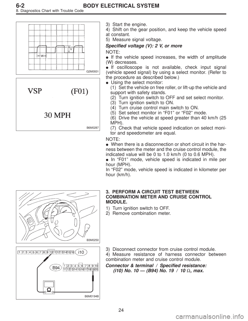
3) Start the engine.
4) Shift on the gear position, and keep the vehicle speed
at constant.
5) Measure signal voltage.
Specified voltage (V): 2 V, or more
NOTE:
�If the vehicle speed increases, the width of amplitude
(W) decreases.
�If oscilloscope is not available, check input signal
(vehicle speed signal) by using a select monitor. (Refer to
the procedure as described below.)
�Using the select monitor:
(1) Set the vehicle on free roller, or lift-up the vehicle and
support with safety stands.
(2) Turn ignition switch to OFF and set select monitor.
(3) Turn ignition switch to ON.
(4) Turn cruise control main switch to ON.
(5) Set select monitor in“F01”or“F02”mode.
(6) Drive the vehicle at speed greater than 40 km/h (25
MPH).
(7) Check that vehicle speed indication on select moni-
tor and speedometer are equal.
NOTE:
�When there is a disconnection or short circuit in the har-
ness between the meter and the cruise control module, the
indicated value will be 0 to 1.0 km/h (0 to 0.6 MPH).
�In“F01”mode, vehicle speed is indicated in mile per
hour (MPH).
In“F02”mode, vehicle speed is indicated in kilometer per
hour (km/h).
B3M0250
3. PERFORM A CIRCUIT TEST BETWEEN
COMBINATION METER AND CRUISE CONTROL
MODULE.
1) Turn ignition switch to OFF.
2) Remove combination meter.
B6M0194B
3) Disconnect connector from cruise control module.
4) Measure resistance of harness connector between
combination meter and cruise control module.
Connector & terminal / Specified resistance:
(i10) No. 10—(B94) No. 19 / 10Ω, max.
24
6-2BODY ELECTRICAL SYSTEM
8. Diagnostics Chart with Trouble Code