Page 819 of 3342
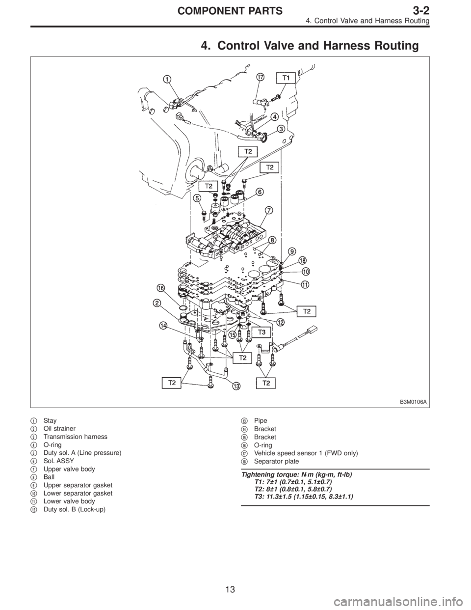
4. Control Valve and Harness Routing
B3M0106A
�1Stay
�
2Oil strainer
�
3Transmission harness
�
4O-ring
�
5Duty sol. A (Line pressure)
�
6Sol. ASSY
�
7Upper valve body
�
8Ball
�
9Upper separator gasket
�
10Lower separator gasket
�
11Lower valve body
�
12Duty sol. B (Lock-up)�
13Pipe
�
14Bracket
�
15Bracket
�
16O-ring
�
17Vehicle speed sensor 1 (FWD only)
�
18Separator plate
Tightening torque: N⋅m (kg-m, ft-lb)
T1: 7±1 (0.7±0.1, 5.1±0.7)
T2: 8±1 (0.8±0.1, 5.8±0.7)
T3: 11.3±1.5 (1.15±0.15, 8.3±1.1)
13
3-2COMPONENT PARTS
4. Control Valve and Harness Routing
Page 832 of 3342
G3M0859
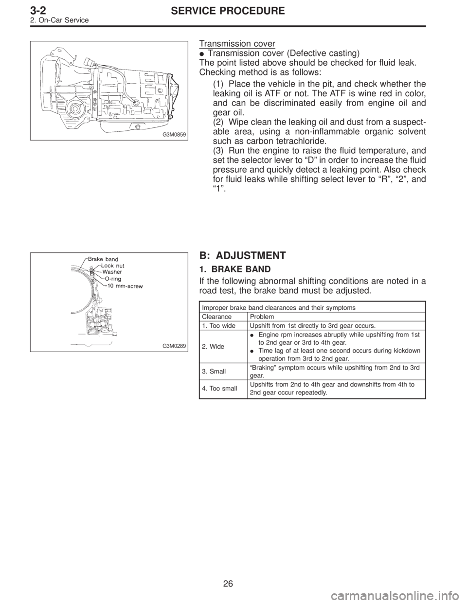
Transmission cover
�Transmission cover (Defective casting)
The point listed above should be checked for fluid leak.
Checking method is as follows:
(1) Place the vehicle in the pit, and check whether the
leaking oil is ATF or not. The ATF is wine red in color,
and can be discriminated easily from engine oil and
gear oil.
(2) Wipe clean the leaking oil and dust from a suspect-
able area, using a non-inflammable organic solvent
such as carbon tetrachloride.
(3) Run the engine to raise the fluid temperature, and
set the selector lever to“D”in order to increase the fluid
pressure and quickly detect a leaking point. Also check
for fluid leaks while shifting select lever to“R”,“2”, and
“1”.
G3M0289
B: ADJUSTMENT
1. BRAKE BAND
If the following abnormal shifting conditions are noted in a
road test, the brake band must be adjusted.
Improper brake band clearances and their symptoms
Clearance Problem
1. Too wide Upshift from 1st directly to 3rd gear occurs.
2. Wide�Engine rpm increases abruptly while upshifting from 1st
to 2nd gear or 3rd to 4th gear.
�Time lag of at least one second occurs during kickdown
operation from 3rd to 2nd gear.
3. Small“Braking”symptom occurs while upshifting from 2nd to 3rd
gear.
4. Too smallUpshifts from 2nd to 4th gear and downshifts from 4th to
2nd gear occur repeatedly.
26
3-2SERVICE PROCEDURE
2. On-Car Service
Page 838 of 3342
G3M0863
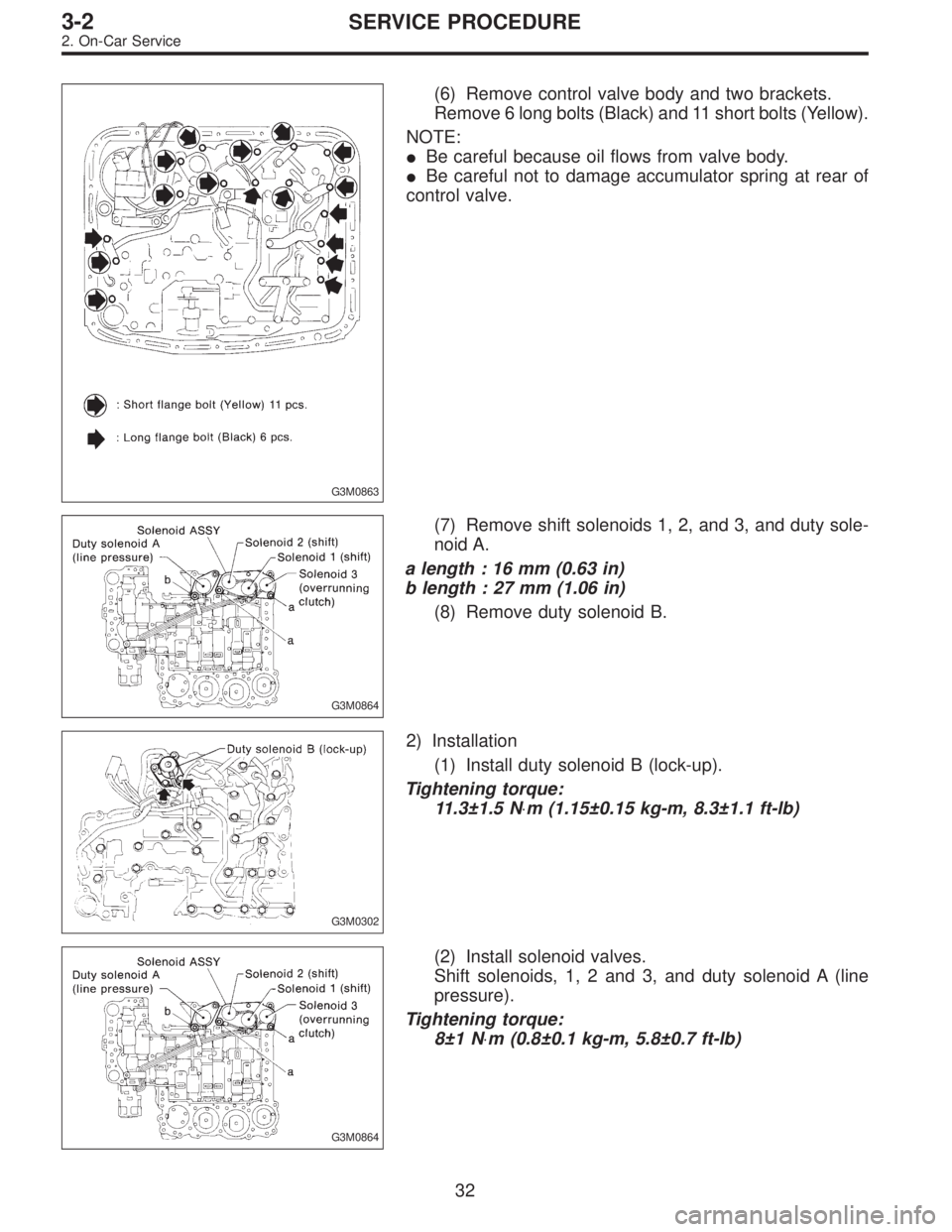
(6) Remove control valve body and two brackets.
Remove 6 long bolts (Black) and 11 short bolts (Yellow).
NOTE:
�Be careful because oil flows from valve body.
�Be careful not to damage accumulator spring at rear of
control valve.
G3M0864
(7) Remove shift solenoids 1, 2, and 3, and duty sole-
noid A.
a length : 16 mm (0.63 in)
b length : 27 mm (1.06 in)
(8) Remove duty solenoid B.
G3M0302
2) Installation
(1) Install duty solenoid B (lock-up).
Tightening torque:
11.3±1.5 N⋅m (1.15±0.15 kg-m, 8.3±1.1 ft-lb)
G3M0864
(2) Install solenoid valves.
Shift solenoids, 1, 2 and 3, and duty solenoid A (line
pressure).
Tightening torque:
8±1 N⋅m (0.8±0.1 kg-m, 5.8±0.7 ft-lb)
32
3-2SERVICE PROCEDURE
2. On-Car Service
Page 847 of 3342
C: LINE PRESSURE TEST
1. GENERAL
If the clutch or the brake band shows a sign of slippage or
shifting sensation is not correct, the line pressure should be
checked.
�Excessive shocks during upshifting or shifting takes
place at a higher point than under normal circumstances,
may be due to the line pressure being too high.
�Slippage or inability to operate the vehicle may, in most
cases, be due to loss of oil pressure for the operation of
the clutch, brake band or control valve.
G3M0869
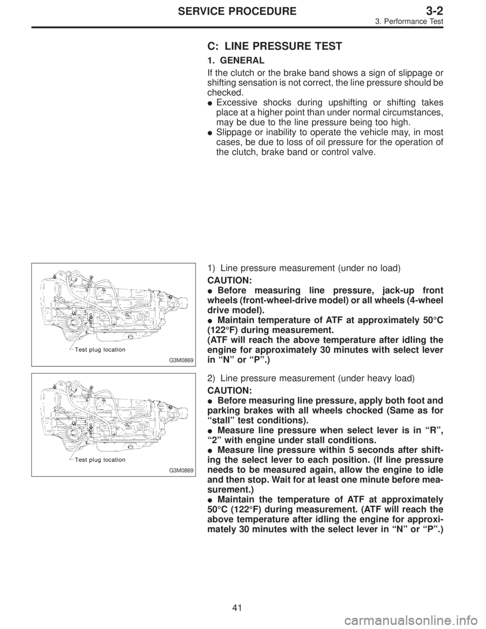
1) Line pressure measurement (under no load)
CAUTION:
�Before measuring line pressure, jack-up front
wheels (front-wheel-drive model) or all wheels (4-wheel
drive model).
�Maintain temperature of ATF at approximately 50°C
(122°F) during measurement.
(ATF will reach the above temperature after idling the
engine for approximately 30 minutes with select lever
in“N”or“P”.)
G3M0869
2) Line pressure measurement (under heavy load)
CAUTION:
�Before measuring line pressure, apply both foot and
parking brakes with all wheels chocked (Same as for
“stall”test conditions).
�Measure line pressure when select lever is in“R”,
“2”with engine under stall conditions.
�Measure line pressure within 5 seconds after shift-
ing the select lever to each position. (If line pressure
needs to be measured again, allow the engine to idle
and then stop. Wait for at least one minute before mea-
surement.)
�Maintain the temperature of ATF at approximately
50°C (122°F) during measurement. (ATF will reach the
above temperature after idling the engine for approxi-
mately 30 minutes with the select lever in“N”or“P”.)
41
3-2SERVICE PROCEDURE
3. Performance Test
Page 848 of 3342
G3M0317
2. TEST METHODS
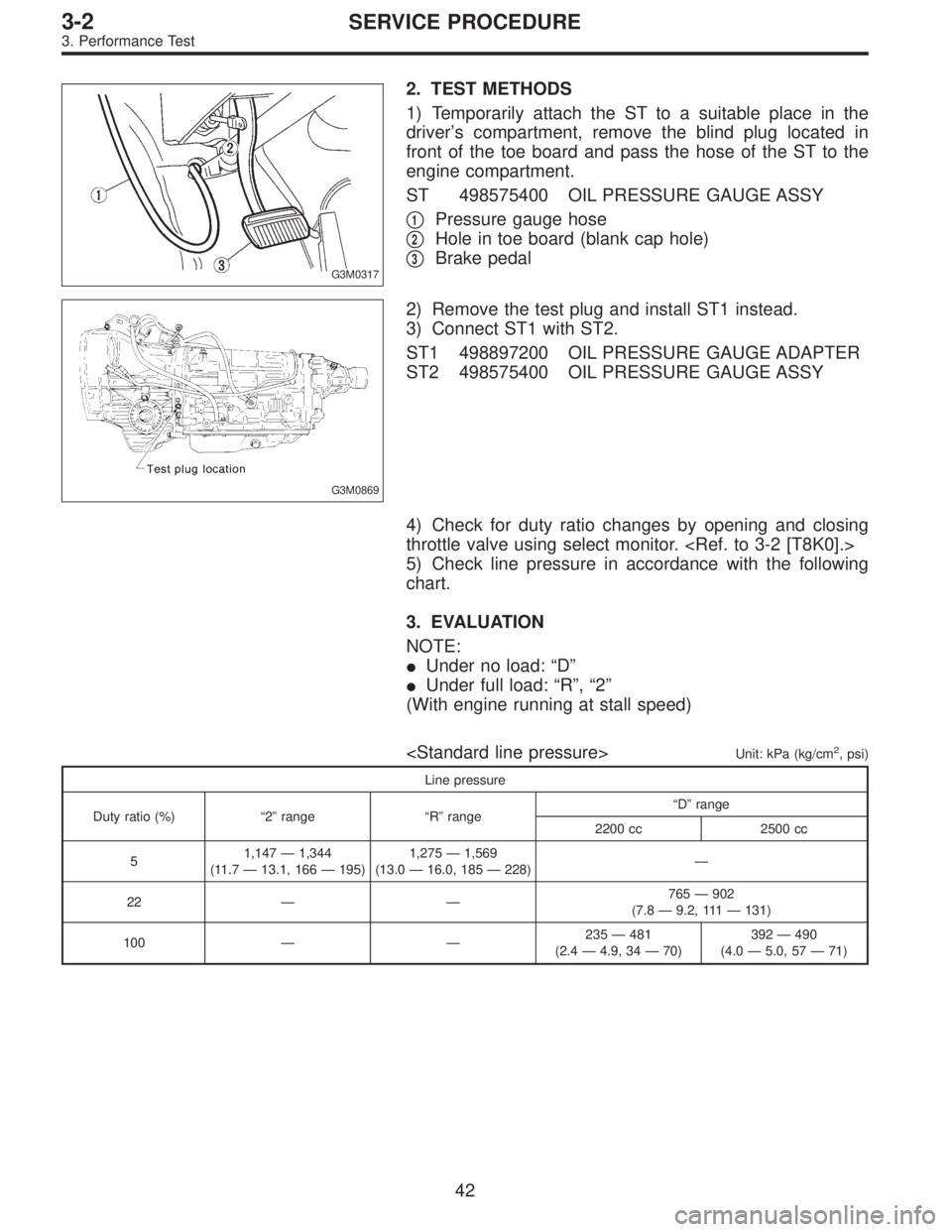
1) Temporarily attach the ST to a suitable place in the
driver’s compartment, remove the blind plug located in
front of the toe board and pass the hose of the ST to the
engine compartment.
ST 498575400 OIL PRESSURE GAUGE ASSY
�
1Pressure gauge hose
�
2Hole in toe board (blank cap hole)
�
3Brake pedal
G3M0869
2) Remove the test plug and install ST1 instead.
3) Connect ST1 with ST2.
ST1 498897200 OIL PRESSURE GAUGE ADAPTER
ST2 498575400 OIL PRESSURE GAUGE ASSY
4) Check for duty ratio changes by opening and closing
throttle valve using select monitor.
5) Check line pressure in accordance with the following
chart.
3. EVALUATION
NOTE:
�Under no load:“D”
�Under full load:“R”,“2”
(With engine running at stall speed)
Unit: kPa (kg/cm2, psi)
Line pressure
Duty ratio (%)“2”range“R”range“D”range
2200 cc 2500 cc
51,147—1,344
(11.7—13.1, 166—195)1,275—1,569
(13.0—16.0, 185—228)—
22——765—902
(7.8—9.2, 111—131)
100——235—481
(2.4—4.9, 34—70)392—490
(4.0—5.0, 57—71)
42
3-2SERVICE PROCEDURE
3. Performance Test
Page 849 of 3342
G3M0870
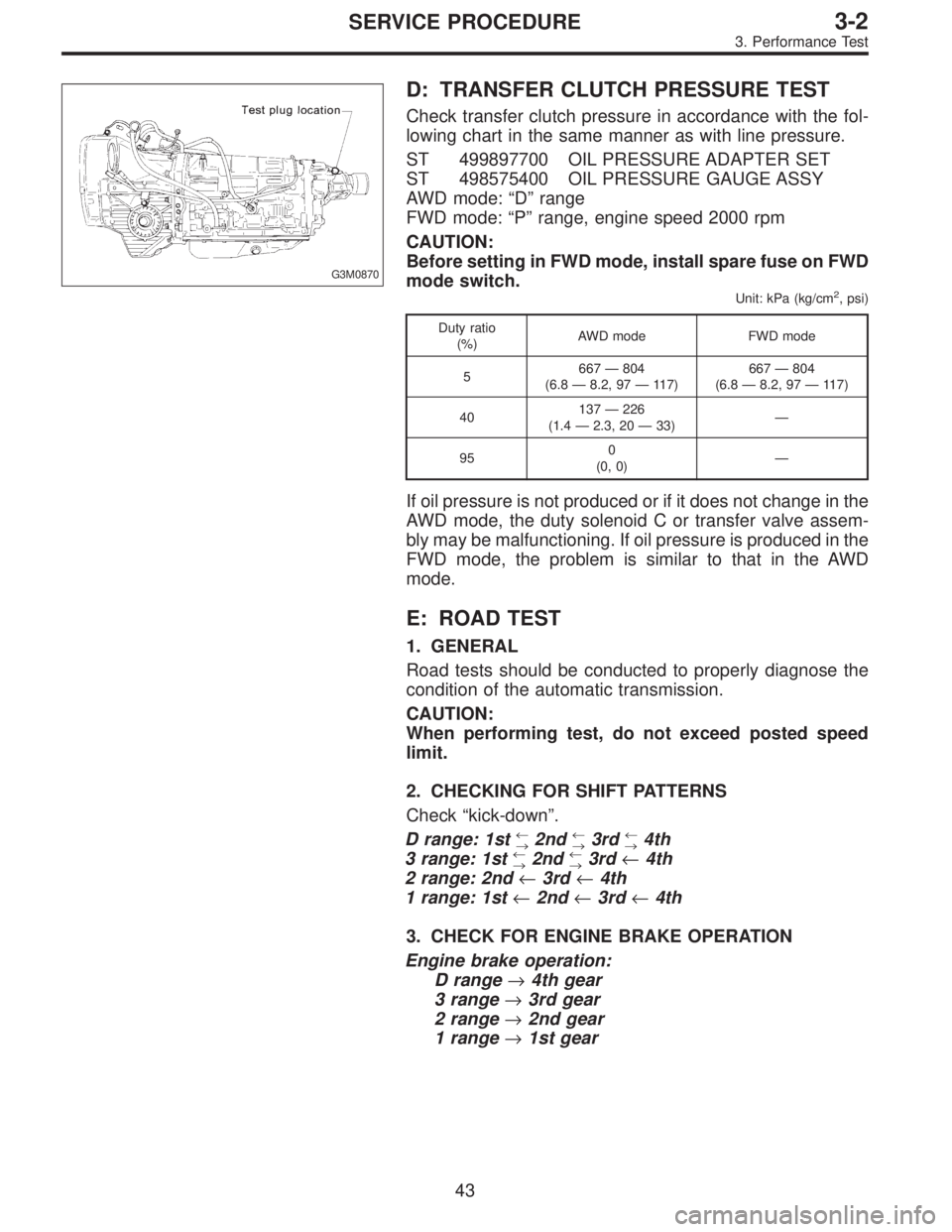
D: TRANSFER CLUTCH PRESSURE TEST
Check transfer clutch pressure in accordance with the fol-
lowing chart in the same manner as with line pressure.
ST 499897700 OIL PRESSURE ADAPTER SET
ST 498575400 OIL PRESSURE GAUGE ASSY
AWD mode:“D”range
FWD mode:“P”range, engine speed 2000 rpm
CAUTION:
Before setting in FWD mode, install spare fuse on FWD
mode switch.
Unit: kPa (kg/cm2, psi)
Duty ratio
(%)AWD mode FWD mode
5667—804
(6.8—8.2, 97—117)667—804
(6.8—8.2, 97—117)
40137—226
(1.4—2.3, 20—33)—
950
(0, 0)—
If oil pressure is not produced or if it does not change in the
AWD mode, the duty solenoid C or transfer valve assem-
bly may be malfunctioning. If oil pressure is produced in the
FWD mode, the problem is similar to that in the AWD
mode.
E: ROAD TEST
1. GENERAL
Road tests should be conducted to properly diagnose the
condition of the automatic transmission.
CAUTION:
When performing test, do not exceed posted speed
limit.
2. CHECKING FOR SHIFT PATTERNS
Check“kick-down”.
D range: 1st
←
→2nd←
→3rd←
→4th
3 range: 1st←
→2nd←
→3rd←4th
2 range: 2nd←3rd←4th
1 range: 1st←2nd←3rd←4th
3. CHECK FOR ENGINE BRAKE OPERATION
Engine brake operation:
D range→4th gear
3 range→3rd gear
2 range→2nd gear
1 range→1st gear
43
3-2SERVICE PROCEDURE
3. Performance Test
Page 850 of 3342
4. CHECK FOR THE AWD FUNCTION
If“tight-corner braking”occurs when the steering wheel is
fully turned at low speed:
1) Determine the applicable trouble code and check the
corresponding duty solenoid C (transfer) for improper
operation.
2) If the solenoid is operating properly, check transfer
clutch pressure.
3) If oil pressure is normal but“tight-corner braking”
occurs:
Check the transfer control valve for sticking, and the trans-
fer clutch facing for wear.
44
3-2SERVICE PROCEDURE
3. Performance Test
Page 862 of 3342
G3M0361
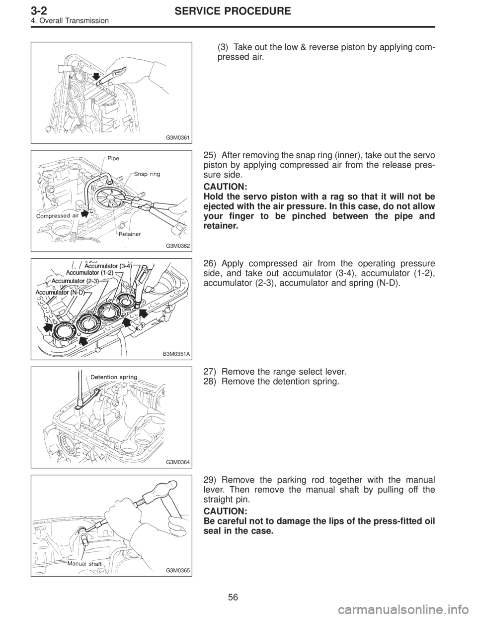
(3) Take out the low & reverse piston by applying com-
pressed air.
G3M0362
25) After removing the snap ring (inner), take out the servo
piston by applying compressed air from the release pres-
sure side.
CAUTION:
Hold the servo piston with a rag so that it will not be
ejected with the air pressure. In this case, do not allow
your finger to be pinched between the pipe and
retainer.
B3M0351A
26) Apply compressed air from the operating pressure
side, and take out accumulator (3-4), accumulator (1-2),
accumulator (2-3), accumulator and spring (N-D).
G3M0364
27) Remove the range select lever.
28) Remove the detention spring.
G3M0365
29) Remove the parking rod together with the manual
lever. Then remove the manual shaft by pulling off the
straight pin.
CAUTION:
Be careful not to damage the lips of the press-fitted oil
seal in the case.
56
3-2SERVICE PROCEDURE
4. Overall Transmission