Page 2462 of 3342
G3M0725
E: MODE F02
—VEHICLE SPEED SENSOR 1 (VSP1)—
F03 = vehicle speed (VSP1):
to be indicated in“km/h”.
CONDITION:
Raise vehicle off ground and operate at constant speed.
SPECIFIED DATA:
Compare speedometer with monitor indications.
Probable cause (if outside“specified data”)
1. Vehicle speed sensor 1
�Check performance characteristics of vehicle speed
sensor 1.
OK
Check TCM and replace if necessary.
G3M0726
F: MODE F04
—VEHICLE SPEED SENSOR 2 (VSP2)—
F05 = vehicle speed (VSP2):
to be indicated in“km/h”.
CONDITION:
Raise vehicle off ground and operate at constant speed.
SPECIFIED DATA:
Compare speedometer with monitor indications.
Probable cause (if outside“specified data”)
1. Vehicle speed sensor 2
�Check performance characteristics of vehicle speed
sensor 2.
OK
Check TCM and replace if necessary.
�
�
58
3-2AUTOMATIC TRANSMISSION AND DIFFERENTIAL
8. Diagnostic Chart with Select Monitor
Page 2463 of 3342
—
CONDITION:
Measure with engine operating at constant speed.
SPECIFIED DATA:
Same as tachometer reading (in combination meter)
Probable cause (if outside“")
G3M0727
G: MODE F06—ENGINE SPEED (EREV)—
CONDITION:
Measure with engine operating at constant speed.
SPECIFIED DATA:
Same as tachometer reading (in combination meter)
Probable cause (if outside“specified data”)
1. Conduct diagnostics in relation to MPFI
system for engine speed.
�OK
Check TCM and replace if necessary.
OBD0386
H: MODE F07
—ATF TEMPERATURE SENSOR (ATFT)—
F08 = ATF temperature (ATFT):
to be indicated in“deg C”.
CONDITION:
�Low ATF temperature (before engine/vehicle starts.)
�High ATF temperature (after driving vehicle for warm-
up.)
SPECIFIED DATA:
�Ambient temperature: ±50°F (±10°C)
(Low ATF temperature)
�ATF temperature: 158—230°F (70—11 0°C)
(High ATF temperature)
�Open harness: 176 deg F (80 deg C)
�Shorted harness: 320 deg F (160 deg C)
Probable cause (if outside“specified data”)
1. ATF temperature sensor
�Check performance characteristics of ATF
temperature sensor.
OK
Check TCM and replace if necessary.
�
59
3-2AUTOMATIC TRANSMISSION AND DIFFERENTIAL
8. Diagnostic Chart with Select Monitor
Page 2464 of 3342
—
CONDITION:
�Ignition switch ON (with engine OFF)
�Measure voltage while operating throttle valve from a
fully closed position to a fully open p")
B3M0383
I: MODE F09
—THROTTLE POSITION SENSOR (THV)—
CONDITION:
�Ignition switch ON (with engine OFF)
�Measure voltage while operating throttle valve from a
fully closed position to a fully open position.
SPECIFIED DATA:
�Fully closed position: 0.5±0.2 V
�Fully open position: 4.6±0.3 V
�From fully closed to fully open position:
Voltage must smoothly decrease.
�Open harness: 5.0±0.3 V
�Shorted harness: 0.00 V
Probable cause (if outside“specified data”)
1. Throttle position sensor
�Check performance characteristics of throttle
position sensor.
OK
Check TCM and replace if necessary.
G3M0730
J: MODE F10—GEAR POSITION (GEAR)—
CONDITION:
Check while driving vehicle (after warm-up).
SPECIFIED DATA:
Gear position (Refer to shift performance characteristics
chart.)
Probable cause (item outside“specified data”)
1. Shift solenoid 1
�Check performance characteristics of shift solenoid
1.
OK
2. Shift solenoid 2
�Check performance characteristics of shift solenoid
2.
OK
3. Shift solenoid 3
�Check performance characteristics of shift solenoid
3.
OK
Check TCM and replace as necessary.
�
�
�
�
60
3-2AUTOMATIC TRANSMISSION AND DIFFERENTIAL
8. Diagnostic Chart with Select Monitor
Page 2465 of 3342
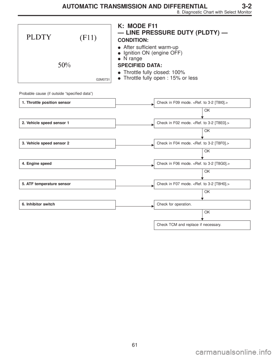
G3M0731
K: MODE F11
—LINE PRESSURE DUTY (PLDTY)—
CONDITION:
�After sufficient warm-up
�Ignition ON (engine OFF)
�N range
SPECIFIED DATA:
�Throttle fully closed: 100%
�Throttle fully open : 15% or less
Probable cause (if outside“specified data”)
1. Throttle position sensor
�Check in F09 mode.
OK
2. Vehicle speed sensor 1
�Check in F02 mode.
OK
3. Vehicle speed sensor 2
�Check in F04 mode.
OK
4. Engine speed
�Check in F06 mode.
OK
5. ATF temperature sensor
�Check in F07 mode.
OK
6. Inhibitor switch
�Check for operation.
OK
Check TCM and replace if necessary.
�
�
�
�
�
�
61
3-2AUTOMATIC TRANSMISSION AND DIFFERENTIAL
8. Diagnostic Chart with Select Monitor
Page 2466 of 3342
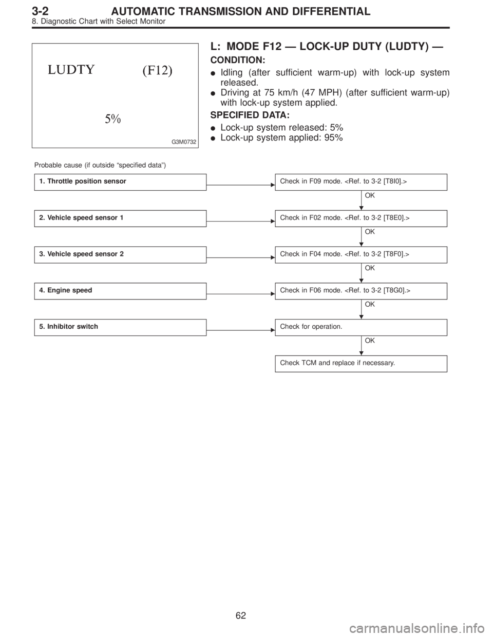
G3M0732
L: MODE F12—LOCK-UP DUTY (LUDTY)—
CONDITION:
�Idling (after sufficient warm-up) with lock-up system
released.
�Driving at 75 km/h (47 MPH) (after sufficient warm-up)
with lock-up system applied.
SPECIFIED DATA:
�Lock-up system released: 5%
�Lock-up system applied: 95%
Probable cause (if outside“specified data”)
1. Throttle position sensor
�Check in F09 mode.
OK
2. Vehicle speed sensor 1
�Check in F02 mode.
OK
3. Vehicle speed sensor 2
�Check in F04 mode.
OK
4. Engine speed
�Check in F06 mode.
OK
5. Inhibitor switch
�Check for operation.
OK
Check TCM and replace if necessary.
�
�
�
�
�
62
3-2AUTOMATIC TRANSMISSION AND DIFFERENTIAL
8. Diagnostic Chart with Select Monitor
Page 2467 of 3342
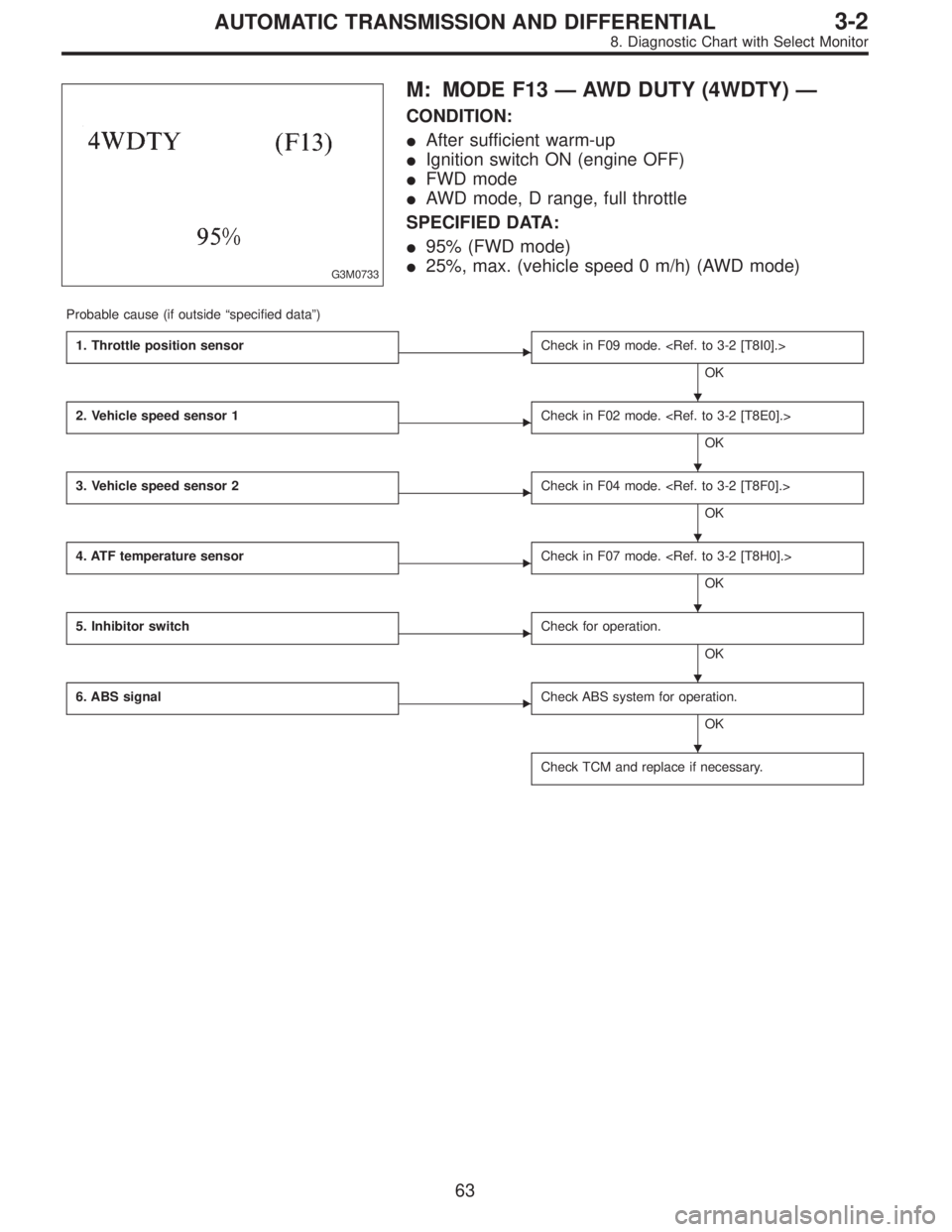
G3M0733
M: MODE F13—AWD DUTY (4WDTY)—
CONDITION:
�After sufficient warm-up
�Ignition switch ON (engine OFF)
�FWD mode
�AWD mode, D range, full throttle
SPECIFIED DATA:
�95% (FWD mode)
�25%, max. (vehicle speed 0 m/h) (AWD mode)
Probable cause (if outside“specified data”)
1. Throttle position sensor
�Check in F09 mode.
OK
2. Vehicle speed sensor 1
�Check in F02 mode.
OK
3. Vehicle speed sensor 2
�Check in F04 mode.
OK
4. ATF temperature sensor
�Check in F07 mode.
OK
5. Inhibitor switch
�Check for operation.
OK
6. ABS signal
�Check ABS system for operation.
OK
Check TCM and replace if necessary.
�
�
�
�
�
�
63
3-2AUTOMATIC TRANSMISSION AND DIFFERENTIAL
8. Diagnostic Chart with Select Monitor
Page 2468 of 3342
B3M0259
N: MODE F14
—THROTTLE POSITION SENSOR POWER
SUPPLY (THVCC)—
CONDITION:
Ignition switch ON (engine OFF)
SPECIFIED DATA:
5.12±0.1 V
Probable cause (Item outside“specified data”)
1. Throttle position sensor power supply
�Check throttle sensor line.
OK
Check TCM and replace if necessary.
B3M0370
O: MODE F15
—MASS AIR FLOW SIGNAL (AFM)—
CONDITION:
�Ignition switch ON (engine ON)
�N range
�Idling
SPECIFIED DATA:
Engine warm-up: 0.5—1.22 V
Probable cause (if outside“specified data”)
1. Mass air flow signal
�Check performance characteristics of mass air flow
signal.
OK
Check TCM and replace if necessary.
�
�
64
3-2AUTOMATIC TRANSMISSION AND DIFFERENTIAL
8. Diagnostic Chart with Select Monitor
Page 2469 of 3342

DISPLAY
LED No. Signal name Symbol
1 FWD switch FF
2 Kick-down switch KD
3——
4——
5 Brake BR
6 ABS switch AB
7 Cruise control set CR
8 Power switch PW
9——
10——
FF KD—— ——BR
AB CR PW—— ——
1
2345
678910
P: MODE FA0
—SWITCH 1 (SW1)—
Reference values
�Lights up when the fuse is installed in FWD switch (No. 1).
�Light up when the brake pedal is depressed (No. 5).
�Light up when the ABS signal is entered (No. 6).
�Lights up when the cruise control is set (No. 7).
NOTE:
LED Nos. 2 and 8 do not come on.
DISPLAY
LED No. Signal name Symbol
1 N/P range switch NP
2 R range switch RR
3 D range switch RD
4 3 range switch R3
5 2 range switch R2
6 1 range switch R1
7 Diagnosis switch SS
8——
9——
10——
NP RR RD R3 R2
R1 SS—— —— ——
1
2345
678910
Q: MODE FA1
—SWITCH 2 (SW2)—
Reference values
�Lights up when the N or P range is selected (No. 1).
�Lights up when the R range is selected (No. 2).
�Lights up when the D range is selected (No. 3).
�Lights up when the 3 range is selected (No. 4).
�Lights up when the 2 range is selected (No. 5).
�Lights up when the 1 range is selected (No. 6).
�Lights up when the diagnosis switch is connected
(No. 7).
NOTE:
If each LED does not illuminate in the above conditions,
inhibitor switch malfunction may occur. Perform diagnostics
on inhibitor switch.
65
3-2AUTOMATIC TRANSMISSION AND DIFFERENTIAL
8. Diagnostic Chart with Select Monitor
—
F03 = vehicle speed (VSP1):
to be indicated in“km/h”.
CONDITION:
Raise vehicle off ground and operate at constant speed.
SPECIFIED DATA:
Com")
—
CONDITION:
Ignition switch ON (engine OFF)
SPECIFIED DATA:
5.12±0.1 V
Probable cause (Item outside“specified data”)
1. Thro")