Page 1476 of 3342
 The A/C system to be tested must have an adequate
refrigerant charge to begin with.
2) The are")
8. Leak Testing
The following points should be kept in mind when conduct-
ing a refrigerant leak test.
1) The A/C system to be tested must have an adequate
refrigerant charge to begin with.
2) The area where the leak test is conducted must be free
of wind and drafts, with still air being the ideal condition.
3) The atmosphere where the leak test is conducted must
be free of refrigerant contamination.
4) Operate the A/C system for approx. 10 minutes, then
turn the engine off an begin the leak test.
5) Refrigerant gas is heavier than air, therefore always
hold the probe below the connection being tested.
6) When checking for a leak along a length of hose or
tube, the leak detector probe must be moved slowly,
approx. 25 mm (1 in) per second making sure probe does
not come in contact with the component being tested.
7) When checking for a leak at a certain point, the leak
detector probe must be held at that point for at least 5
seconds.
G4M0609
1. CHECK THE SYSTEM PRESSURE
With gauges connected to the A/C system, operate the A/C
and confirm that the high side pressure is above 690 kPa
(7.03 kg/cm
2, 100 psi). If not, evacuate and charge the
system before leak checking (refer to evacuation and
charging sections).
2. CLEAN CONNECTIONS BEFORE TESTING
Before testing, use a clean shop towel to wipe off refriger-
ant oil, dirt, or foreign material from all of the connections
and components to be tested.
NOTE:
Since refrigerant oil absorbs refrigerant, excess oil on or
near a connection may falsely signal a leak.
B4M0089
3. CALIBRATE LEAK DETECTOR
Refer to the manufacturer’s instructions for the particular
type of detector used and calibrate the instrument.
CAUTION:
Always make sure that the probe tip filter is clean and
free of contamination.
23
4-7SERVICE PROCEDURE
8. Leak Testing
Page 1481 of 3342

After stabilization and discharge, replace the component,
adding the appropriate amount of oil (ND-OIL9) to the new
component before installation.
ConditionProper chargi")
3. OIL REPLACEMENT (RHD MODEL)
After stabilization and discharge, replace the component,
adding the appropriate amount of oil (ND-OIL9) to the new
component before installation.
ConditionProper charging
methodAmount of oil to
be added
m�(US fl oz,
lmp fl oz)
Replacement of compressorRemove all oil
from new
compressor and
charge it with
amount of oil
shown in right
column.70 (2.4, 2.5)
Replacement of evaporator—70 (2.4, 2.5)
Replacement of receiver drier
(Liquid tank)Oil need not be
added.—
Replacement of
condenserThere is no sign
of leakage.Oil need not be
added.—
There is
evidence of a
large amount of
oil leakage from
condenser.—50 (1.7, 1.8)
Replacement of
flexible hose or
aluminum pipeThere is no sign
of leakage.Oil need not be
added.—
There is
evidence of a
large amount of
oil leakage.—50 (1.7, 1.8)
Gas leakageThere is no sign
of leakage.Oil need not be
added.—
There is
evidence of a
large amount of
oil leakage.—50 (1.7, 1.8)
If the compressor is replaced (after stabilization):
1) Drain and measure the oil from the original compressor.
2) Drain the oil from the replacement compressor and refill
with the same amount that was drained from the original
[20 m�(0.7 US fl oz, 0.7 Imp fl oz) minimum]. Always use
ND-OIL9 for the replacement oil.
27
4-7SERVICE PROCEDURE
9. Lubrication
Page 1484 of 3342

11. Compressor
Compressor is a swash plate type. When trouble occurs,
replace compressor as a single unit.
B4M0090
A: COMPRESSOR CLUTCH INSPECTION
Compressor clutch trouble is often caused by clutch slip-
page and noise. Check and take corrective measures, as
required.
1) Remove belt cover.
2) Check that clearance between drive plate and pulley
over the entire perimeter is within specifications.
Clearance:
0.3 — 0.6 mm (0.012 — 0.024 in)
B4M0091
3) Check that voltage applied to magnetic coil is at least
10.5 volts.
4) When noise is noted, check that it originates in either
compressor or pulley bearing.
B4M0760A
B: REMOVAL
1) Disconnect ground cable from battery.
2) Discharge refrigerant using refrigerant recovery system.
(1) Fully close low-pressure valve of manifold gauge.
(2) Connect low-pressure charging hose of manifold
gauge to low-pressure service valve.
(3) Open low-pressure manifold gauge valve slightly,
and slowly discharge refrigerant from system.
CAUTION:
Do not allow refrigerant to rush out. Otherwise, com-
pressor oil will be discharged along with refrigerant.
30
4-7SERVICE PROCEDURE
11. Compressor
Page 1741 of 3342
 External parts
Check for the existence of dirt or cracks on the battery
case, top cover, vent plugs, and terminal posts. If
necessary, clean with water and wipe with a dry")
B: INSPECTION
1. BATTERY
1) External parts
Check for the existence of dirt or cracks on the battery
case, top cover, vent plugs, and terminal posts. If
necessary, clean with water and wipe with a dry cloth.
Apply a thin coat of grease on the terminal posts to prevent
corrosion.
2) Electrolyte level
Check the electrolyte level in each cell. If the level is below
MIN LEVEL, bring the level to MAX LEVEL by pouring dis-
tilled water into the battery cell. Do not fill beyond MAX
LEVEL.
WARNING:
�Electrolyte has toxicity; be careful handling the
fluid.
�Avoid contact with skin, eyes or clothing. Especially
at contact with eyes, blush with water for 15 minutes
and get prompt medical attention.
�Batteries produce explosive gasses. Keep sparks,
flame, cigarettes away.
�Ventilate when charging or using in enclosed space.
�For safety, in case an explosion does occur, wear
eye protection or shield your eyes when working near
any battery. Never lean over a battery.
�Do not let battery fluid contact eyes, skin, fabrics, or
paint-work because battery fluid is corrosive acid.
�To lessen the risk of sparks, remove rings, metal
watch-bands, and other metal jewelry. Never allow
metal tools to contact the positive battery terminal and
anything connected to it while you are at the same time
in contact with any other metallic portion of the vehicle
because a short circuit will be caused.
5
6-2SERVICE PROCEDURE
2. Battery
Page 1742 of 3342
 Specific gravity of electrolyte
Measure specific gravity of electrolyte using a hydrometer
and a thermometer.
Specific gravity varies with temperature of electrolyte so
that it must be corr")
G6M0103
3) Specific gravity of electrolyte
Measure specific gravity of electrolyte using a hydrometer
and a thermometer.
Specific gravity varies with temperature of electrolyte so
that it must be corrected at 20°C (68°F) using the follow-
ing equation:
S
20= St + 0.0007 x (t � 20)
S
20:Specific gravity corrected at electrolyte tempera-
ture of 20°C (68°F)
St :Measured specific gravity
t :Measured temperature °C
Determine whether or not battery must be charged,
according to corrected specific gravity.
Standard specific gravity: 1.220 — 1.290 [at 20°C
(68°F)]
Measuring the specific gravity of the electrolyte in the bat-
tery will disclose the state of charge of the battery. The
relation between the specific gravity and the state of
charge is as shown in figure.
C: CHARGING
WARNING:
�Do not bring an open flame close to the battery at
this time.
CAUTION:
�Prior to charging, corroded terminals should be
cleaned with a brush and common baking soda solu-
tion.
�Be careful since battery electrolyte overflows while
charging the battery.
�Observe instructions when handling battery
charger.
�Before charging the battery on vehicle, disconnect
battery ground terminal. Failure to follow this rule may
damage generator’s diodes or other electrical units.
1. NORMAL CHARGING
Charge the battery at current value specified by manufac-
turer or at approximately 1/10 of battery’s ampere hour
rating.
2. QUICK CHARGING
Quick charging is a method in which the battery is charged
in a short period of time with a relatively large current by
using a quick charger.
Since a large current flow raises electrolyte temperature,
the battery is subject to damage if the large current is used
for prolonged time. For this reason, the quick charging
must be carried out within a current range that will not
increase the electrolyte temperature above 40°C (104°F).
It should be also remembered that the quick charging is a
temporary means to bring battery voltage up to a fair value
and, as a rule, a battery should be charged slowly with a
low current.
6
6-2SERVICE PROCEDURE
2. Battery
Page 1743 of 3342
![SUBARU LEGACY 1997 Service Repair Manual CAUTION:
�Observe the items in 1. NORMAL CHARGING 6-2
[W2C1].
�Never use more than 10 amperes when charging the
battery because that will shorten battery life.
3. JUDGMENT OF BATTERY IN CHARGED
CONDIT](/manual-img/17/57434/w960_57434-1742.png "SUBARU LEGACY 1997 Service Repair Manual CAUTION:
�Observe the items in 1. NORMAL CHARGING 6-2
[W2C1].
�Never use more than 10 amperes when charging the
battery because that will shorten battery life.
3. JUDGMENT OF BATTERY IN CHARGED
CONDIT")
CAUTION:
�Observe the items in 1. NORMAL CHARGING 6-2
[W2C1].
�Never use more than 10 amperes when charging the
battery because that will shorten battery life.
3. JUDGMENT OF BATTERY IN CHARGED
CONDITION
1) Specific gravity of electrolyte is held at a specific value
in a range from 1.250 to 1.290 for more than one hour.
2) Voltage per battery cell is held at a specific value in a
range from 2.5 to 2.8 volts for more than one hour.
4. CHECK HYDROMETER FOR STATE OF CHARGE
Hydrometer indicator State of charge Required action
Green dot Above 65% Load test
Dark dot Below 65% Charge battery
Clear dot Low electrolyteReplace battery.* (If
cranking complaint)
*: Check electrical system before replacement.
B6M0236
3. Ignition Switch
A: REMOVAL AND INSTALLATION
1. IGNITION SWITCH
1) Remove screws, separate upper column cover and
lower column cover.
2) Remove instrument panel lower cover.
B6M0333
3) Disconnect ignition switch connector from body har-
ness.
4) Using a drift and hammer, hit the torn bolt head to
loosen and remove the ignition switch.
B6M0334A
5) When installing, tighten the connecting bolt until its
head twists off.
7
6-2SERVICE PROCEDURE
2. Battery - 3. Ignition Switch
Page 1744 of 3342
![SUBARU LEGACY 1997 Service Repair Manual CAUTION:
�Observe the items in 1. NORMAL CHARGING 6-2
[W2C1].
�Never use more than 10 amperes when charging the
battery because that will shorten battery life.
3. JUDGMENT OF BATTERY IN CHARGED
CONDIT](/manual-img/17/57434/w960_57434-1743.png "SUBARU LEGACY 1997 Service Repair Manual CAUTION:
�Observe the items in 1. NORMAL CHARGING 6-2
[W2C1].
�Never use more than 10 amperes when charging the
battery because that will shorten battery life.
3. JUDGMENT OF BATTERY IN CHARGED
CONDIT")
CAUTION:
�Observe the items in 1. NORMAL CHARGING 6-2
[W2C1].
�Never use more than 10 amperes when charging the
battery because that will shorten battery life.
3. JUDGMENT OF BATTERY IN CHARGED
CONDITION
1) Specific gravity of electrolyte is held at a specific value
in a range from 1.250 to 1.290 for more than one hour.
2) Voltage per battery cell is held at a specific value in a
range from 2.5 to 2.8 volts for more than one hour.
4. CHECK HYDROMETER FOR STATE OF CHARGE
Hydrometer indicator State of charge Required action
Green dot Above 65% Load test
Dark dot Below 65% Charge battery
Clear dot Low electrolyteReplace battery.* (If
cranking complaint)
*: Check electrical system before replacement.
B6M0236
3. Ignition Switch
A: REMOVAL AND INSTALLATION
1. IGNITION SWITCH
1) Remove screws, separate upper column cover and
lower column cover.
2) Remove instrument panel lower cover.
B6M0333
3) Disconnect ignition switch connector from body har-
ness.
4) Using a drift and hammer, hit the torn bolt head to
loosen and remove the ignition switch.
B6M0334A
5) When installing, tighten the connecting bolt until its
head twists off.
7
6-2SERVICE PROCEDURE
2. Battery - 3. Ignition Switch
Page 1895 of 3342
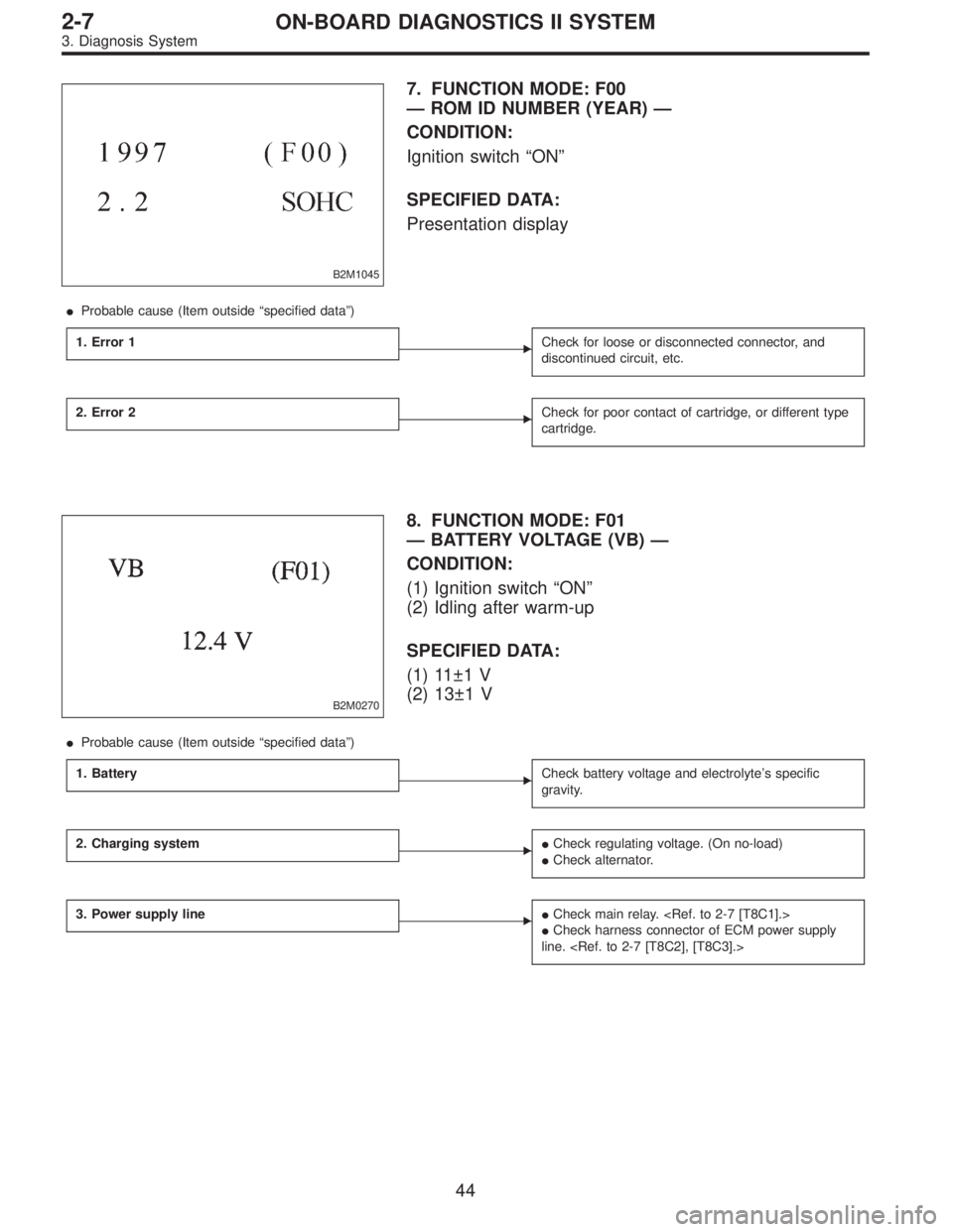
B2M1045
7. FUNCTION MODE: F00
— ROM ID NUMBER (YEAR) —
CONDITION:
Ignition switch“ON”
SPECIFIED DATA:
Presentation display
�Probable cause (Item outside“specified data”)
1. Error 1
�Check for loose or disconnected connector, and
discontinued circuit, etc.
2. Error 2�Check for poor contact of cartridge, or different type
cartridge.
B2M0270
8. FUNCTION MODE: F01
— BATTERY VOLTAGE (VB) —
CONDITION:
(1) Ignition switch“ON”
(2) Idling after warm-up
SPECIFIED DATA:
(1) 11±1 V
(2) 13±1 V
�Probable cause (Item outside“specified data”)
1. Battery
�Check battery voltage and electrolyte’s specific
gravity.
2. Charging system��Check regulating voltage. (On no-load)
�Check alternator.
3. Power supply line��Check main relay.
�Check harness connector of ECM power supply
line.
44
2-7ON-BOARD DIAGNOSTICS II SYSTEM
3. Diagnosis System