Page 338 of 3342
1. Engine Trouble in General
Numbers shown in the chart refer to the possibility of reason for the
trouble in order (“Very often”to“Rarely”)
1—Very often
2—Sometimes
3—Rarely
TROUBLE
Engine will not start.
Rough idle and engine stall
Low output, hesitation and poor acceleration
Surging
Engine does not return to idle.
Dieseling (Run-on)
After burning in exhaust system
Knocking
Excessive engine oil consumption
Excessive fuel consumption Starter does not turn.
Initial combustion does not occur.
Initial combustion occurs.
Engine stalls after initial combustion.
POSSIBLE CAUSE
STARTER
2�Defective battery-to-starter harness
3�Defective starter switch
3�Defective inhibitor switch
23�Defective starter
BATTERY
1�Poor terminal connection
1�Run-down battery
2�Defective charging system
1111111111 1Fuel injection system
Diagnostics II System.>
75
2-3DIAGNOSTICS
1. Engine Trouble in General
Page 418 of 3342
1. Engine Trouble in General
Numbers shown in the chart refer to the possibility of reason for the
trouble in order (“Very often”to“Rarely”)
1—Very often
2—Sometimes
3—Rarely
TROUBLE
Engine will not start.
Rough idle and engine stall
Low output, hesitation and poor acceleration
Surging
Engine does not return to idle.
Dieseling (Run-on)
After burning in exhaust system
Knocking
Excessive engine oil consumption
Excessive fuel consumption Starter does not turn.
Initial combustion does not occur.
Initial combustion occurs.
Engine stalls after initial combustion.
POSSIBLE CAUSE
STARTER
2�Defective battery-to-starter harness
3�Defective starter switch
3�Defective inhibitor switch
23�Defective starter
BATTERY
1�Poor terminal connection
1�Run-down battery
2�Defective charging system
1111111111 1Fuel injection system
Diagnostics II System.>
77
2-3bDIAGNOSTICS
1. Engine Trouble in General
Page 1467 of 3342
Tools and Equipment Description
�THERMOMETER
PocketTHERMOMETERSare available from either industrial
hardware store or commercial refrigeration supply houses.
G4M0578
�ELECTRONIC LEAK DETECTOR
AnELECTRONIC LEAK DETECTORcan be obtained from
either a specialty tool supply or an A/C equipment supplier.
G4M0579
�WEIGHT SCALE
AWEIGHT SCALEsuch as an electronic charging scale or a
bathroom scale with digital display will be needed if a 13.6 kg
(30 lb) refrigerant container is used.
G4M0580
14
4-7SERVICE PROCEDURE
3. Tools and Equipment
Page 1471 of 3342
6. Discharge the System
CAUTION:
The following points should be kept in mind when dis-
charging the system.
�Be certain that goggles and gloves are worn.
�Connect refrigerant recovery system to manifold
gauge set and remove recycle refrigerant from A/C
system.
NOTE:
Refer to appropriate refrigerant recovery system instruction
manual for operation.
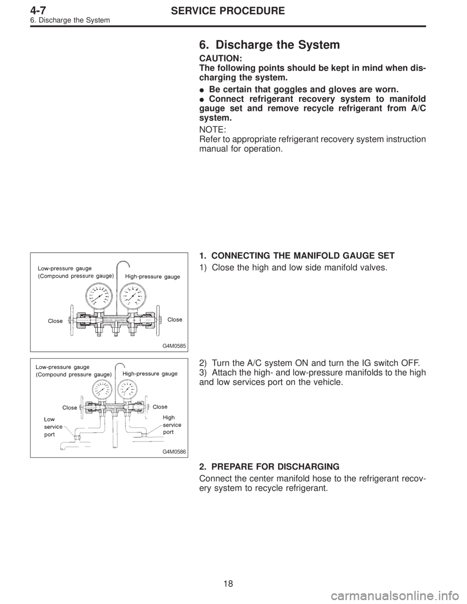
G4M0585
1. CONNECTING THE MANIFOLD GAUGE SET
1) Close the high and low side manifold valves.
G4M0586
2) Turn the A/C system ON and turn the IG switch OFF.
3) Attach the high- and low-pressure manifolds to the high
and low services port on the vehicle.
2. PREPARE FOR DISCHARGING
Connect the center manifold hose to the refrigerant recov-
ery system to recycle refrigerant.
18
4-7SERVICE PROCEDURE
6. Discharge the System
Page 1472 of 3342
 Be certain that goggles and gloves are worn.
2) If bulk refr")
G4M0596
7. Evacuating and Charging
The following points should be kept in mind when evacu-
ating and charging with a manifold gauge set.
1) Be certain that goggles and gloves are worn.
2) If bulk refrigerant [13.6 kg (30 lb) canister] is used, be
certain to weigh the charge amount carefully, using the
correct equipment, to avoid overcharging the system.
3) The charging procedure described in this section
begins by chargingliquidrefrigerant into the high- pres-
sure side of the systemwith the engine off.The proce-
dure is completed by charging refrigerantvaporinto the
low-pressure side of the system with the engine running.
CAUTION:
Never open the high-pressure manifold valve when the
engine is running.
G4M0597
1. CONNECT THE GAUGE SET
1) Close the high- and low-pressure manifold valves.
2) Attach the low-pressure manifold hose to the low- pres-
sure service port on the vehicle. Check the low- pressure
gauge. If more than 68.6 kPa (0.70 kg/cm
2, 10 psi) is
indicated, discharge the system prior to charging.
3) Attach the high-pressure manifold hose to the high-
pressure service port on the vehicle.
4) Connect the center hose from the manifold to the
vacuum pump.
5) Turn on the vacuum pump.
6) Slowly open the low-pressure manifold valve.
7) When the low-pressure gauge reaches approximately
66.43 kPa (498.3 mmHg, 19.62 inHg), slowly open the
high-pressure manifold valve.
G4M0598
8) Maintain a minimum vacuum level of 100.56 kPa (754.4
mmHg, 29.70 inHg) for a minimum of 15 minutes on a new
system or 30 minutes for an in-service system.
NOTE:
The gauge will read 4 kPa (25 mmHg, 1 inHg) less for
every 304.8 m (1,000 ft) above sea level.
19
4-7SERVICE PROCEDURE
7. Evacuating and Charging
Page 1473 of 3342
 After 15 minutes (or more) of evacuation, close the
high-pressure manifold valve.
2) Close the low-pressure manifold valve.
3) Turn off the vacuum pump.
G4M060")
G4M0599
2. PERFORM A VACUUM LEAK TEST
1) After 15 minutes (or more) of evacuation, close the
high-pressure manifold valve.
2) Close the low-pressure manifold valve.
3) Turn off the vacuum pump.
G4M0600
4) Note the low side gauge reading.
5) After 5 minutes, re-check the low-pressure gauge read-
ing.
If the vacuum level has changed more than 4 kPa (25
mmHg, 1 inHg), perform an HFC-134a leak test.
If the vacuum reading is about the same as noted in step
2-4), continue on to step 2-6).
G4M0980
6) Carefully attach the can tap to the refrigerant can by
following the can tap manufacturer’s instructions.
7) Disconnect the center manifold hose from the vacuum
pump and connect the hose to the tap valve.
G4M0981
8) If a 13.6 kg (30 lb) container of refrigerant is used a
weight scale will be needed. This scale is to determine the
amount of refrigerant that is used.
Connect the center hose from the manifold to the valve.
Place the 13.6 kg (30 lb) container on the scale, valve end
down.
G4M0603
3. PURGE THE CENTER HOSE
1) Verify that all three hose connections are tight at the
manifold gauge set.
2) Open the valve on the HFC-134a source.
3)With safety equipment in place (goggles and
gloves), use extreme cautionand loosen the center hose
connection at the manifold and allow the HFC-134a to
escape for no more than two or three seconds, then quickly
retighten the hose fitting at the manifold.
20
4-7SERVICE PROCEDURE
7. Evacuating and Charging
Page 1474 of 3342
 Connect a tachometer to the engine.
2)With the engine off, start charging by slowly opening
the high-pressure manifold valve.
NOTE:
The initial cha")
G4M0604
4. INITIAL CHARGING THROUGH THE HIGH SIDE
1) Connect a tachometer to the engine.
2)With the engine off, start charging by slowly opening
the high-pressure manifold valve.
NOTE:
The initial charge rate can be increased by immersing the
can in lukewarm [Below 38°C (100°F)] water for a short
time.
G4M0605
5. CHECK THE GAUGE READINGS
When both the high- and low-pressure gauge readings are
about equal, or the HFC-134a source is empty, or the sys-
tem has been filled to specifications, close the high- pres-
sure manifold valve.
6. ADD ADDITIONAL CANS
If the HFC-134a source is exhausted, first close the high-
pressure manifold valve, second, close the can tap valve,
then slowly purge the refrigerant from the service hose by
loosening the fitting at the can tap. Repeat steps 15
through 19 as necessary.
G4M0606
7. COMPLETE CHARGING THROUGH THE LOW SIDE
1) Verify that the high-pressure manifold valve is closed
(should have already been closed).
2) Verify that the low-pressure manifold valve is closed
(should have already been closed).
G4M0607
3) With the A/C switch off and the windows rolled down,
start the engine and run at idle rpm.
4) Set the A/C controls on maximum cool and set the
blower speed on the highest setting.
5) Quickly turn the A/C switch on-off-on-off a few times to
prevent initial compressor damage due to“load shock.”
Finish this operation with the A/C switch in the ON position.
6) Raise engine rpm to approximately 1,500 rpm.
21
4-7SERVICE PROCEDURE
7. Evacuating and Charging
Page 1475 of 3342
 With the refrigerant source connected and the service
hose purged, slowly open the low-pressure manifold valve,
while checking the low-pressure gauge reading.
CAUTION:")
G4M0608
8. CHARGE THE SYSTEM
1) With the refrigerant source connected and the service
hose purged, slowly open the low-pressure manifold valve,
while checking the low-pressure gauge reading.
CAUTION:
The refrigerant source must be positioned for vapor
(valve up).
2) Keep the low side pressure below 276 kPa (2.81
kg/cm
2, 40 psi) by using the low-pressure manifold valve to
regulate the flow of refrigerant into the system.
3) When the system is fully charged, close the low- pres-
sure manifold valve.
4) Close the valve at the refrigerant source.
�Refrigerant capacity
Unit: kg (lb)
Refrigerant Minimum Maximum
HFC-134a 0.55 (1.21) 0.65 (1.43)
9. COMPLETE ALL SYSTEM CHECKS
1) Evaluate the system performance (refer to performance
testing section).
2) Perform leak detection test.
CAUTION:
Always perform leak checking in an environment free
of refrigerant pollution.
Do not disconnect the high- or low-pressure hoses
from the vehicle before leak checking.
10. DISCONNECT THE MANIFOLD GAUGE SET
Remove the high- or low-pressure hoses from the service
ports and install the service port caps.
22
4-7SERVICE PROCEDURE
7. Evacuating and Charging

1—Very often
2—Sometimes
3—Rarely
TROUBLE
Eng")

1—Very often
2—Sometimes
3—Rarely
TROUBLE
Eng")