Page 1579 of 3342
5) Installation is in the reverse order of removal.
Tightening torque:
7.4±2.0 N⋅m (0.75±0.2 kg-m, 5.4±1.4 ft-lb)
B5M0305
20. Roof Spoiler (Station Wagon 2500
cc GT model only)
A: REMOVAL AND INSTALLATION
1) Open rear gate and remove rear gate trim upper and
side.
2) Remove high-mount stop light.
B5M0415A
3) Remove plastic caps and harness covers.
B5M0306
4) Remove roof spoiler mounting nuts.
CAUTION:
�When removing nuts, be careful not to drop them
inside rear gate.
�Be careful since two-sided tape is placed between
roof spoiler and body panel.
5) Installation is in the reverse order of removal.
Tightening torque:
7.4±2.0 N⋅m (0.75±0.2 kg-m, 5.4±1.4 ft-lb)
B5M0416
21. Side Spoiler (2500 cc GT model
only)
A: REMOVAL AND INSTALLATION
1) Remove tapping screws, clip and end cover.
2) Installation is in the reverse order of removal.
60
5-1SERVICE PROCEDURE
19. Rear Spoiler (4 Door Sedan 2500 cc GT model only) - 21. Side Spoiler (2500 cc GT model only)
Page 1580 of 3342
B5M0417
22. Front Under Spoiler (All models
except 2500 cc GT)
A: REMOVAL AND INSTALLATION
1) Remove clips.
2) Installation is in the reverse order of removal.
B5M0418
23. Airdam Skirt (2500 cc GT model
only)
A: REMOVAL AND INSTALLATION
1) Remove airdam skirt mounting bolts and clips.
2) Installation is in the reverse order of removal.
B5M0419
24. Rear Under Spoiler (2500 cc GT
model only)
A: REMOVAL AND INSTALLATION
1) Remove tapping screws and clips.
2) Installation is in the reverse order of removal.
NOTE:
�12 tapping screws are used for 4 Door Sedan.
�14 tapping screws are used for Station Wagon.
61
5-1SERVICE PROCEDURE
22. Front Under Spoiler (All models except 2500 cc GT) - 24. Rear Under Spoiler (2500 cc GT model only)
Page 1581 of 3342
B5M0417
22. Front Under Spoiler (All models
except 2500 cc GT)
A: REMOVAL AND INSTALLATION
1) Remove clips.
2) Installation is in the reverse order of removal.
B5M0418
23. Airdam Skirt (2500 cc GT model
only)
A: REMOVAL AND INSTALLATION
1) Remove airdam skirt mounting bolts and clips.
2) Installation is in the reverse order of removal.
B5M0419
24. Rear Under Spoiler (2500 cc GT
model only)
A: REMOVAL AND INSTALLATION
1) Remove tapping screws and clips.
2) Installation is in the reverse order of removal.
NOTE:
�12 tapping screws are used for 4 Door Sedan.
�14 tapping screws are used for Station Wagon.
61
5-1SERVICE PROCEDURE
22. Front Under Spoiler (All models except 2500 cc GT) - 24. Rear Under Spoiler (2500 cc GT model only)
Page 1582 of 3342
B5M0417
22. Front Under Spoiler (All models
except 2500 cc GT)
A: REMOVAL AND INSTALLATION
1) Remove clips.
2) Installation is in the reverse order of removal.
B5M0418
23. Airdam Skirt (2500 cc GT model
only)
A: REMOVAL AND INSTALLATION
1) Remove airdam skirt mounting bolts and clips.
2) Installation is in the reverse order of removal.
B5M0419
24. Rear Under Spoiler (2500 cc GT
model only)
A: REMOVAL AND INSTALLATION
1) Remove tapping screws and clips.
2) Installation is in the reverse order of removal.
NOTE:
�12 tapping screws are used for 4 Door Sedan.
�14 tapping screws are used for Station Wagon.
61
5-1SERVICE PROCEDURE
22. Front Under Spoiler (All models except 2500 cc GT) - 24. Rear Under Spoiler (2500 cc GT model only)
Page 1584 of 3342
1. Door and Rear Gate
A: DOOR ALIGNMENT
B5M0051A
2
5-2SERVICE DATA
1. Door and Rear Gate
Page 1594 of 3342

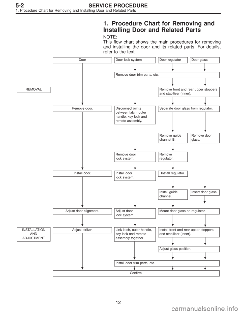
1. Procedure Chart for Removing and
Installing Door and Related Parts
NOTE:
This flow chart shows the main procedures for removing
and installing the door and its related parts. For details,
refer to the text.
DoorDoor lock systemDoor regulator
�
Door glass
�
Remove door trim parts, etc.
�
REMOVALRemove front and rear upper stoppers
and stabilizer (inner).
�
Remove door.Disconnect joints
between latch, outer
handle, key lock and
remote assembly.Separate door glass from regulator.
Remove guide
channel B.Remove door
glass.
Remove door
lock system.Remove
regulator.
Install door.Install door
lock system.Install regulator.
Install guide
channel.Insert door glass.
�
Adjust door alignment.Adjust door
lock system.Mount door glass on regulator.
�
INSTALLATION
AND
ADJUSTMENTAdjust striker.Link latch, outer handle,
key lock and remote
assembly together.Install front and rear upper stoppers
and stabilizer (inner).
�
Adjust glass position.
��
Install door trim parts, etc.
���
Confirm.
�
�
���
��
��
���
��
���
���
�
�
�
12
5-2SERVICE PROCEDURE
1. Procedure Chart for Removing and Installing Door and Related Parts
Page 1595 of 3342
G5M0486
2. Door
A: REMOVAL AND INSTALLATION
1. DOOR ASSY
1) Remove lower trim and disconnect connectors from
body harness.
2) Place a cloth or a wood block under door to prevent
damage, and support it with a jack.
3) Remove checker pin by driving it upward. Be careful not
to damage door and body.
G5M0385
4) Remove bolts (M8) securing upper and lower hinges to
door, and remove door from hinges.
Tightening torque:
25±3 N⋅m (2.5±0.3 kg-m, 18.1±2.2 ft-lb)
5) Remove hinges by loosening hinges mounting bolt (M8)
off of body.
Tightening torque:
29±5 N⋅m (3.0±0.5 kg-m, 21.7±3.6 ft-lb)
CAUTION:
Work carefully to avoid damaging door.
6) Installation is in the reverse order of removal.
NOTE:
Apply grease to moving parts of door hinges.
B5M0329A
2. TRIM PANEL
1) Press retainer spring�
1with a thin flat bladed screw-
driver and then remove regulator handle�
2. (models with-
out power window)
B5M0061A
2) Remove gusset cover�1and three screws.
13
5-2SERVICE PROCEDURE
2. Door
Page 1596 of 3342

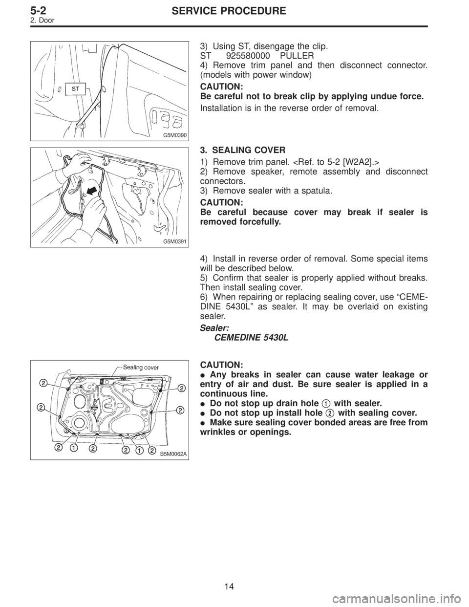
G5M0390
3) Using ST, disengage the clip.
ST 925580000 PULLER
4) Remove trim panel and then disconnect connector.
(models with power window)
CAUTION:
Be careful not to break clip by applying undue force.
Installation is in the reverse order of removal.
G5M0391
3. SEALING COVER
1) Remove trim panel.
2) Remove speaker, remote assembly and disconnect
connectors.
3) Remove sealer with a spatula.
CAUTION:
Be careful because cover may break if sealer is
removed forcefully.
4) Install in reverse order of removal. Some special items
will be described below.
5) Confirm that sealer is properly applied without breaks.
Then install sealing cover.
6) When repairing or replacing sealing cover, use “CEME-
DINE 5430L” as sealer. It may be overlaid on existing
sealer.
Sealer:
CEMEDINE 5430L
B5M0062A
CAUTION:
�Any breaks in sealer can cause water leakage or
entry of air and dust. Be sure sealer is applied in a
continuous line.
�Do not stop up drain hole�
1with sealer.
�Do not stop up install hole�
2with sealing cover.
�Make sure sealing cover bonded areas are free from
wrinkles or openings.
14
5-2SERVICE PROCEDURE
2. Door