Page 1621 of 3342
7. Rear Quarter Glass
A: REMOVAL
1. 4 DOOR MODEL
B5M0091A
1) Remove rear quarter molding.
2) Remove glass in the same manner as in windshield.
2. WAGON MODEL
B5M0092A
1) Remove rear quarter molding.
2) Remove glass in the same manner as in windshield.
G5M0497
B: INSTALLATION
1) Finish surface of adhesive layer on body.
Using a putty knife, etc., cut layer of adhesive stick firmly
to body and finish it into a smooth surface of about 2 mm
(0.08 in) in thickness.
CAUTION:
Be careful not to damage body finish.
38
5-2SERVICE PROCEDURE
7. Rear Quarter Glass
Page 1622 of 3342
2) Cleaning of body surface
(1) Remove chips, dirt and dust from body surface.
(2) Clean body wall surface and upper surface of adhe-
sive layer with a solvent such as alcohol or white gaso-
line.
3) Cleaning glass
(1) Remove dirt and dust from surface of glass to be
adhered.
(2) Clean surface of glass to be adhered with alcohol
or white gasoline.
G5M0495
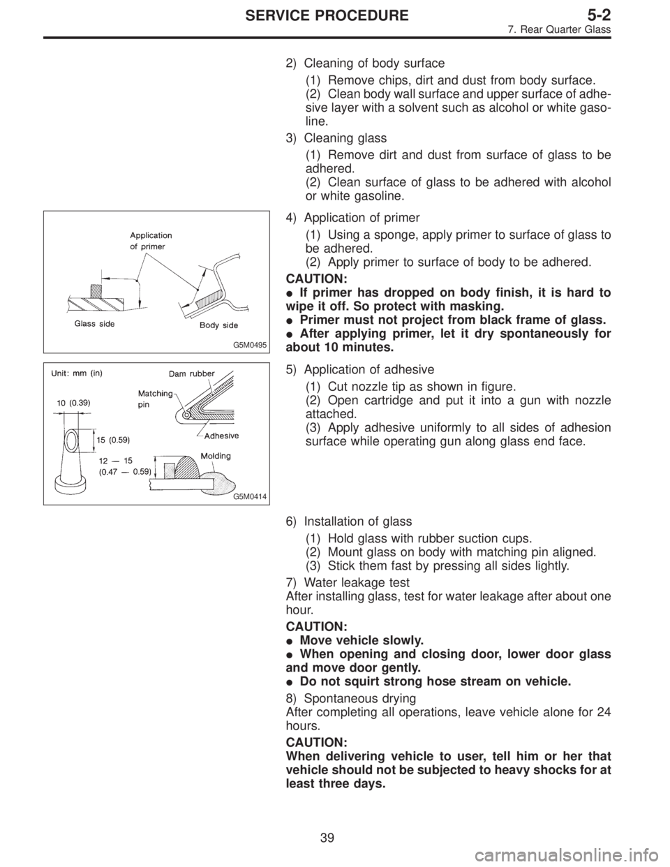
4) Application of primer
(1) Using a sponge, apply primer to surface of glass to
be adhered.
(2) Apply primer to surface of body to be adhered.
CAUTION:
�If primer has dropped on body finish, it is hard to
wipe it off. So protect with masking.
�Primer must not project from black frame of glass.
�After applying primer, let it dry spontaneously for
about 10 minutes.
G5M0414
5) Application of adhesive
(1) Cut nozzle tip as shown in figure.
(2) Open cartridge and put it into a gun with nozzle
attached.
(3) Apply adhesive uniformly to all sides of adhesion
surface while operating gun along glass end face.
6) Installation of glass
(1) Hold glass with rubber suction cups.
(2) Mount glass on body with matching pin aligned.
(3) Stick them fast by pressing all sides lightly.
7) Water leakage test
After installing glass, test for water leakage after about one
hour.
CAUTION:
�Move vehicle slowly.
�When opening and closing door, lower door glass
and move door gently.
�Do not squirt strong hose stream on vehicle.
8) Spontaneous drying
After completing all operations, leave vehicle alone for 24
hours.
CAUTION:
When delivering vehicle to user, tell him or her that
vehicle should not be subjected to heavy shocks for at
least three days.
39
5-2SERVICE PROCEDURE
7. Rear Quarter Glass
Page 1633 of 3342
G5M0342
1. Front Seat
A: REMOVAL
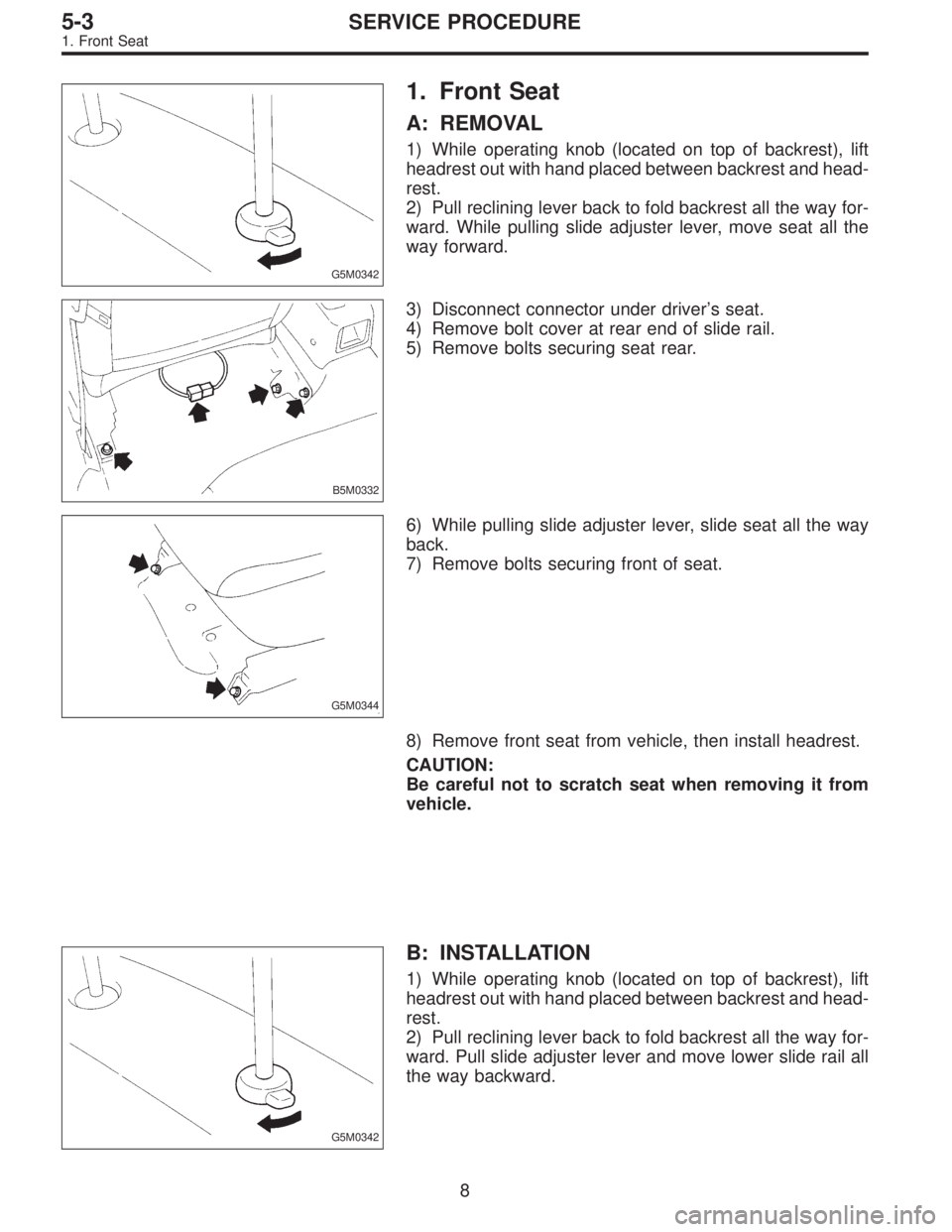
1) While operating knob (located on top of backrest), lift
headrest out with hand placed between backrest and head-
rest.
2) Pull reclining lever back to fold backrest all the way for-
ward. While pulling slide adjuster lever, move seat all the
way forward.
B5M0332
3) Disconnect connector under driver’s seat.
4) Remove bolt cover at rear end of slide rail.
5) Remove bolts securing seat rear.
G5M0344
6) While pulling slide adjuster lever, slide seat all the way
back.
7) Remove bolts securing front of seat.
8) Remove front seat from vehicle, then install headrest.
CAUTION:
Be careful not to scratch seat when removing it from
vehicle.
G5M0342
B: INSTALLATION
1) While operating knob (located on top of backrest), lift
headrest out with hand placed between backrest and head-
rest.
2) Pull reclining lever back to fold backrest all the way for-
ward. Pull slide adjuster lever and move lower slide rail all
the way backward.
8
5-3SERVICE PROCEDURE
1. Front Seat
Page 1634 of 3342
G5M0341
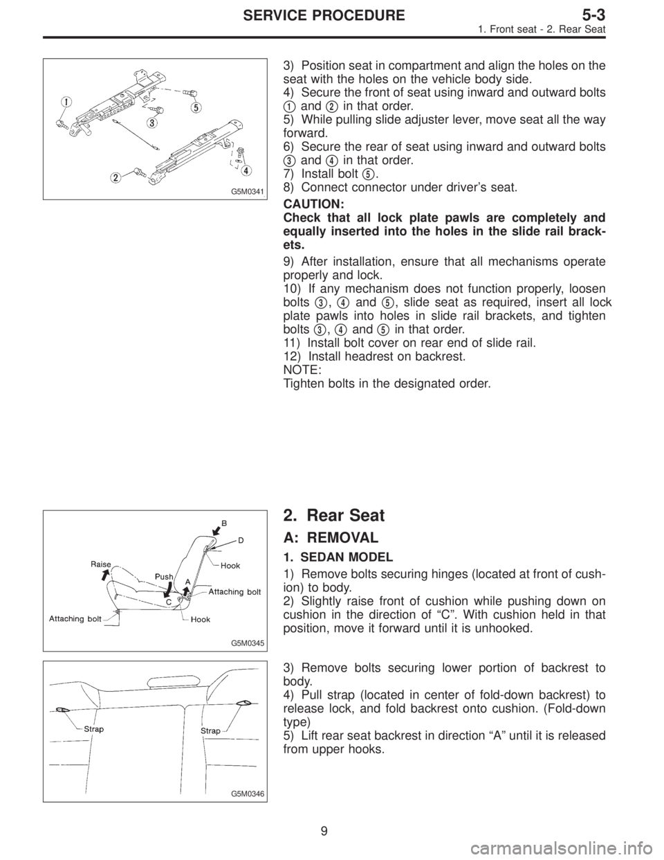
3) Position seat in compartment and align the holes on the
seat with the holes on the vehicle body side.
4) Secure the front of seat using inward and outward bolts
�
1and�2in that order.
5) While pulling slide adjuster lever, move seat all the way
forward.
6) Secure the rear of seat using inward and outward bolts
�
3and�4in that order.
7) Install bolt�
5.
8) Connect connector under driver’s seat.
CAUTION:
Check that all lock plate pawls are completely and
equally inserted into the holes in the slide rail brack-
ets.
9) After installation, ensure that all mechanisms operate
properly and lock.
10) If any mechanism does not function properly, loosen
bolts�
3,�4and�5, slide seat as required, insert all lock
plate pawls into holes in slide rail brackets, and tighten
bolts�
3,�4and�5in that order.
11) Install bolt cover on rear end of slide rail.
12) Install headrest on backrest.
NOTE:
Tighten bolts in the designated order.
G5M0345
2. Rear Seat
A: REMOVAL
1. SEDAN MODEL
1) Remove bolts securing hinges (located at front of cush-
ion) to body.
2) Slightly raise front of cushion while pushing down on
cushion in the direction of“C”. With cushion held in that
position, move it forward until it is unhooked.
G5M0346
3) Remove bolts securing lower portion of backrest to
body.
4) Pull strap (located in center of fold-down backrest) to
release lock, and fold backrest onto cushion. (Fold-down
type)
5) Lift rear seat backrest in direction“A”until it is released
from upper hooks.
9
5-3SERVICE PROCEDURE
1. Front seat - 2. Rear Seat
Page 1635 of 3342
G5M0341
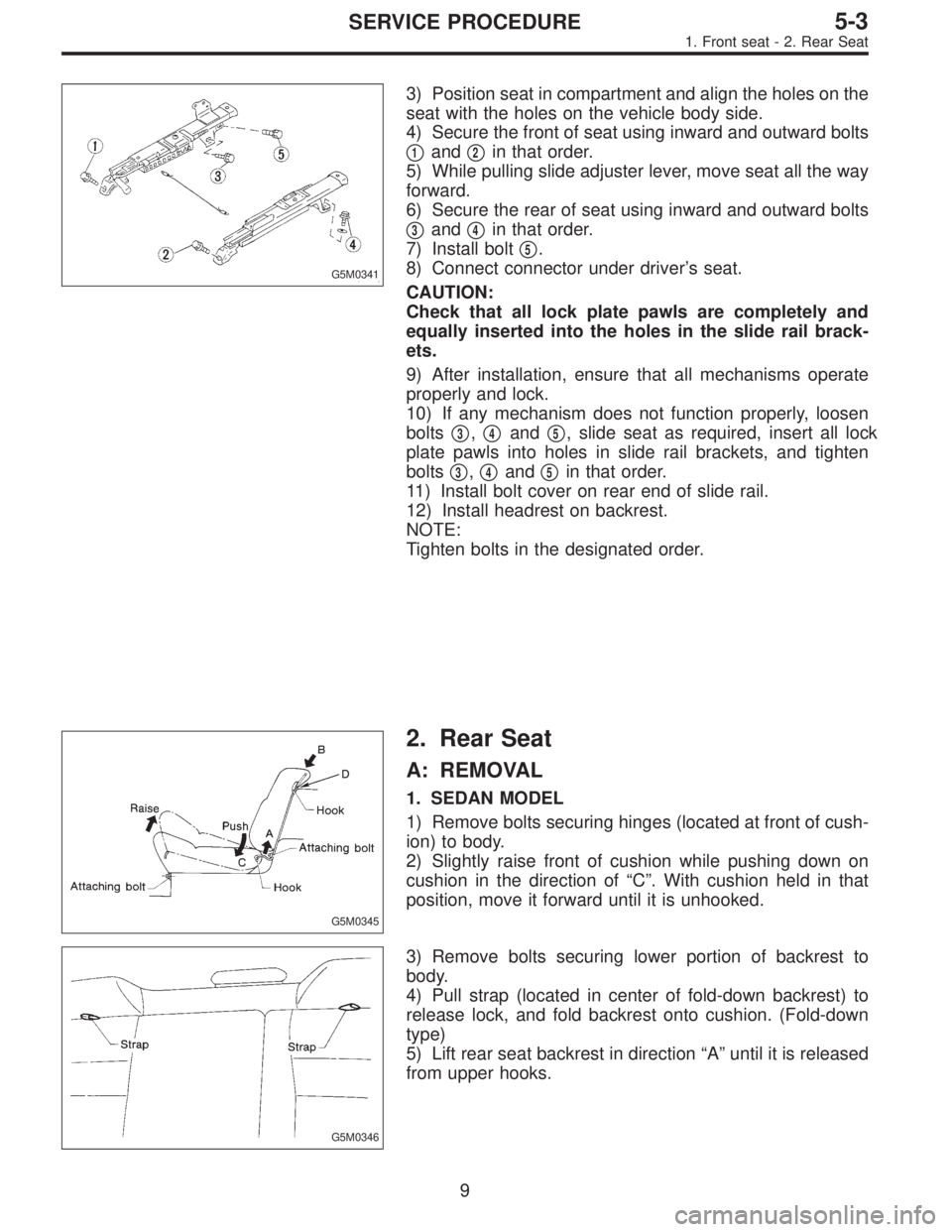
3) Position seat in compartment and align the holes on the
seat with the holes on the vehicle body side.
4) Secure the front of seat using inward and outward bolts
�
1and�2in that order.
5) While pulling slide adjuster lever, move seat all the way
forward.
6) Secure the rear of seat using inward and outward bolts
�
3and�4in that order.
7) Install bolt�
5.
8) Connect connector under driver’s seat.
CAUTION:
Check that all lock plate pawls are completely and
equally inserted into the holes in the slide rail brack-
ets.
9) After installation, ensure that all mechanisms operate
properly and lock.
10) If any mechanism does not function properly, loosen
bolts�
3,�4and�5, slide seat as required, insert all lock
plate pawls into holes in slide rail brackets, and tighten
bolts�
3,�4and�5in that order.
11) Install bolt cover on rear end of slide rail.
12) Install headrest on backrest.
NOTE:
Tighten bolts in the designated order.
G5M0345
2. Rear Seat
A: REMOVAL
1. SEDAN MODEL
1) Remove bolts securing hinges (located at front of cush-
ion) to body.
2) Slightly raise front of cushion while pushing down on
cushion in the direction of“C”. With cushion held in that
position, move it forward until it is unhooked.
G5M0346
3) Remove bolts securing lower portion of backrest to
body.
4) Pull strap (located in center of fold-down backrest) to
release lock, and fold backrest onto cushion. (Fold-down
type)
5) Lift rear seat backrest in direction“A”until it is released
from upper hooks.
9
5-3SERVICE PROCEDURE
1. Front seat - 2. Rear Seat
Page 1636 of 3342
G5M0350
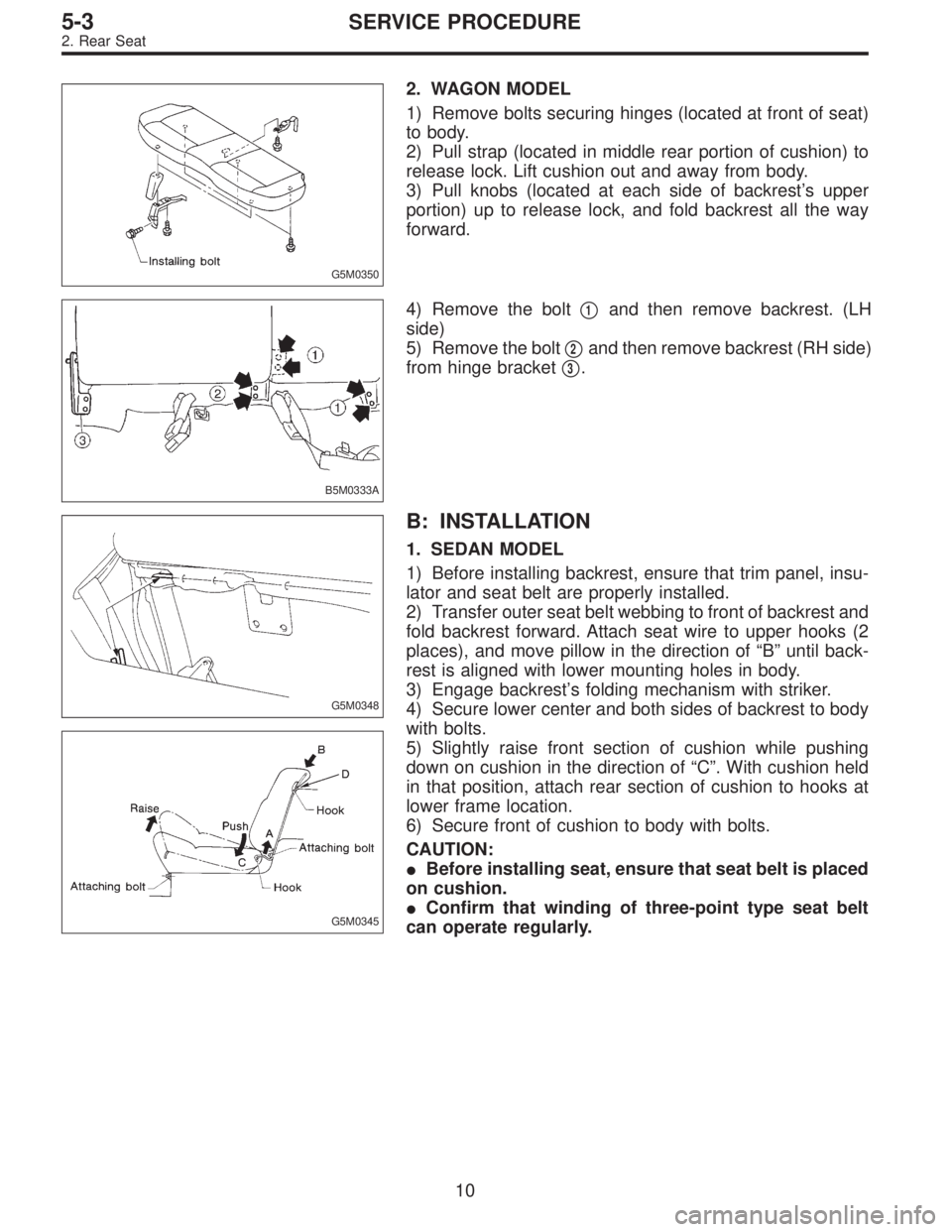
2. WAGON MODEL
1) Remove bolts securing hinges (located at front of seat)
to body.
2) Pull strap (located in middle rear portion of cushion) to
release lock. Lift cushion out and away from body.
3) Pull knobs (located at each side of backrest’s upper
portion) up to release lock, and fold backrest all the way
forward.
B5M0333A
4) Remove the bolt�1and then remove backrest. (LH
side)
5) Remove the bolt�
2and then remove backrest (RH side)
from hinge bracket�
3.
G5M0348
G5M0345
B: INSTALLATION
1. SEDAN MODEL
1) Before installing backrest, ensure that trim panel, insu-
lator and seat belt are properly installed.
2) Transfer outer seat belt webbing to front of backrest and
fold backrest forward. Attach seat wire to upper hooks (2
places), and move pillow in the direction of“B”until back-
rest is aligned with lower mounting holes in body.
3) Engage backrest’s folding mechanism with striker.
4) Secure lower center and both sides of backrest to body
with bolts.
5) Slightly raise front section of cushion while pushing
down on cushion in the direction of“C”. With cushion held
in that position, attach rear section of cushion to hooks at
lower frame location.
6) Secure front of cushion to body with bolts.
CAUTION:
�Before installing seat, ensure that seat belt is placed
on cushion.
�Confirm that winding of three-point type seat belt
can operate regularly.
10
5-3SERVICE PROCEDURE
2. Rear Seat
Page 1637 of 3342
2. WAGON MODEL
Installation is in the reverse order of removal.
CAUTION:
�Do not allow center seat belt to get under cushion
when folding cushion.
�Ensure that side seat belt tongue is free from cush-
ion and trim panel.
�Lift front of cushion to ensure that cushion is prop-
erly locked.
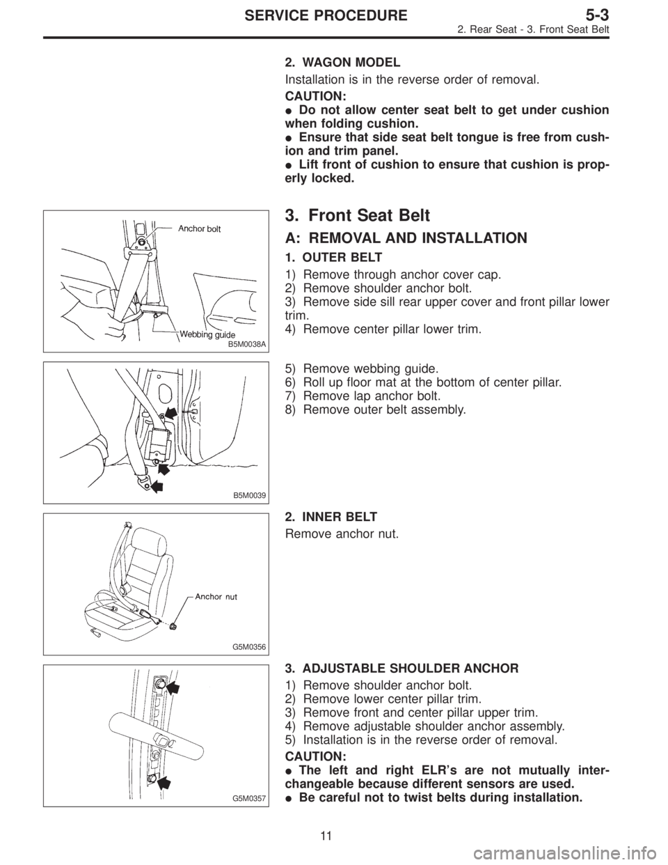
B5M0038A
3. Front Seat Belt
A: REMOVAL AND INSTALLATION
1. OUTER BELT
1) Remove through anchor cover cap.
2) Remove shoulder anchor bolt.
3) Remove side sill rear upper cover and front pillar lower
trim.
4) Remove center pillar lower trim.
B5M0039
5) Remove webbing guide.
6) Roll up floor mat at the bottom of center pillar.
7) Remove lap anchor bolt.
8) Remove outer belt assembly.
G5M0356
2. INNER BELT
Remove anchor nut.
G5M0357
3. ADJUSTABLE SHOULDER ANCHOR
1) Remove shoulder anchor bolt.
2) Remove lower center pillar trim.
3) Remove front and center pillar upper trim.
4) Remove adjustable shoulder anchor assembly.
5) Installation is in the reverse order of removal.
CAUTION:
�The left and right ELR’s are not mutually inter-
changeable because different sensors are used.
�Be careful not to twist belts during installation.
11
5-3SERVICE PROCEDURE
2. Rear Seat - 3. Front Seat Belt
Page 1638 of 3342
2. WAGON MODEL
Installation is in the reverse order of removal.
CAUTION:
�Do not allow center seat belt to get under cushion
when folding cushion.
�Ensure that side seat belt tongue is free from cush-
ion and trim panel.
�Lift front of cushion to ensure that cushion is prop-
erly locked.
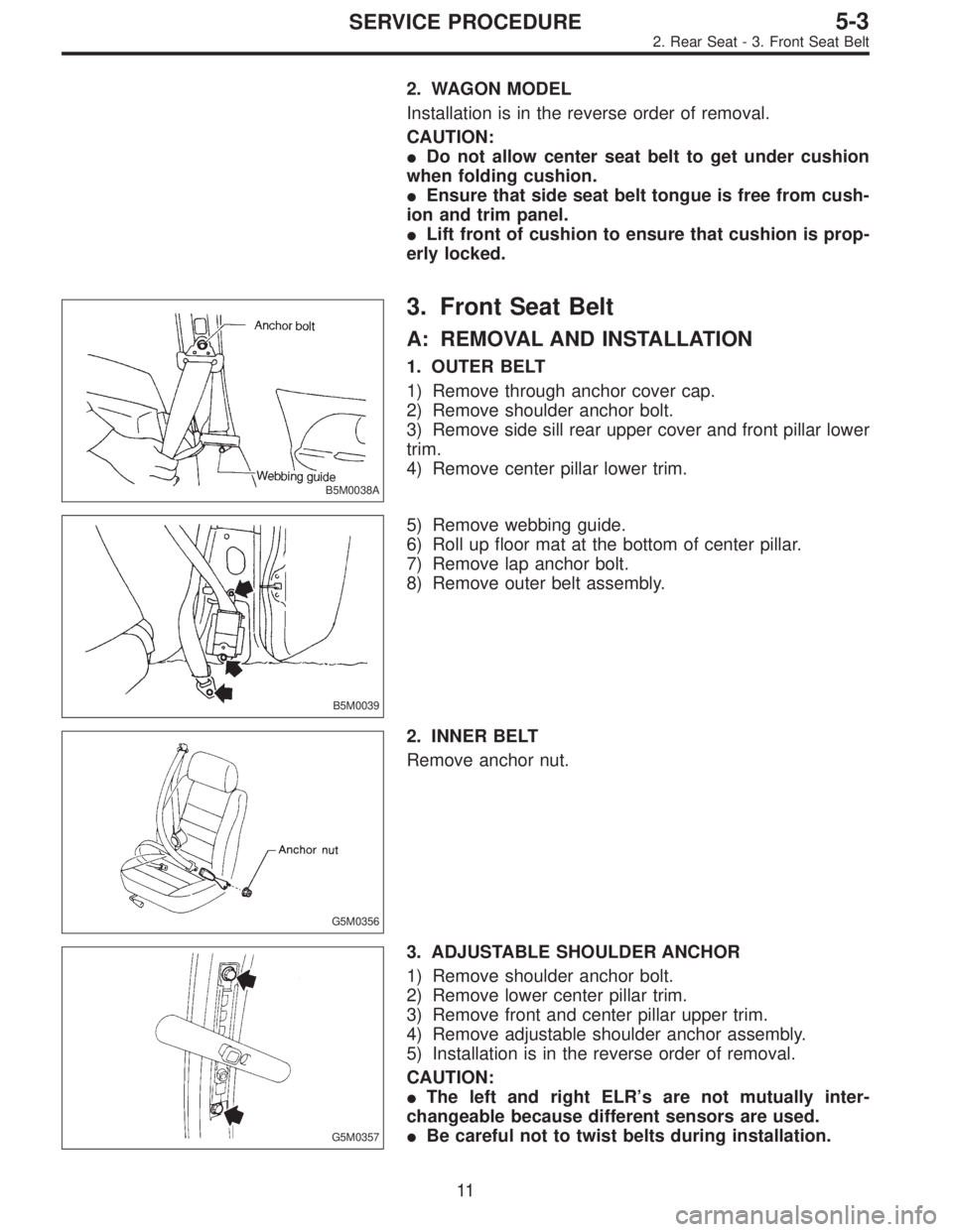
B5M0038A
3. Front Seat Belt
A: REMOVAL AND INSTALLATION
1. OUTER BELT
1) Remove through anchor cover cap.
2) Remove shoulder anchor bolt.
3) Remove side sill rear upper cover and front pillar lower
trim.
4) Remove center pillar lower trim.
B5M0039
5) Remove webbing guide.
6) Roll up floor mat at the bottom of center pillar.
7) Remove lap anchor bolt.
8) Remove outer belt assembly.
G5M0356
2. INNER BELT
Remove anchor nut.
G5M0357
3. ADJUSTABLE SHOULDER ANCHOR
1) Remove shoulder anchor bolt.
2) Remove lower center pillar trim.
3) Remove front and center pillar upper trim.
4) Remove adjustable shoulder anchor assembly.
5) Installation is in the reverse order of removal.
CAUTION:
�The left and right ELR’s are not mutually inter-
changeable because different sensors are used.
�Be careful not to twist belts during installation.
11
5-3SERVICE PROCEDURE
2. Rear Seat - 3. Front Seat Belt