Page 1393 of 3342
D: ABS SEQUENCE CONTROL
1) Under the ABS sequence control, after the hydraulic
unit solenoid valve is driven, the operation of the hydraulic
unit can be checked by means of the brake tester or pres-
sure gauge.
2) ABS sequence control can be started by diagnosis con-
nector or select monitor.
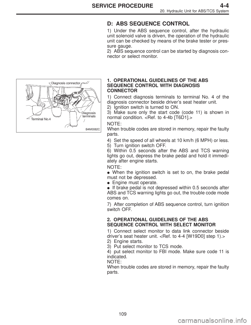
B4M0082C
1. OPERATIONAL GUIDELINES OF THE ABS
SEQUENCE CONTROL WITH DIAGNOSIS
CONNECTOR
1) Connect diagnosis terminals to terminal No. 4 of the
diagnosis connector beside driver’s seat heater unit.
2) Ignition switch is turned to ON.
3) Make sure only the start code (code 11) is shown in
normal condition.
NOTE:
When trouble codes are stored in memory, repair the faulty
parts.
4) Set the speed of all wheels at 10 km/h (6 MPH) or less.
5) Turn ignition switch OFF.
6) Within 0.5 seconds after the ABS and TCS warning
lights go out, depress the brake pedal and hold it immedi-
ately after engine starts.
NOTE:
�When the ignition switch is set to on, the brake pedal
must not be depressed.
�Engine must operate.
�If brake pedal is not depressed within 0.5 seconds after
ABS and TCS warning lights go out, the trouble code mode
comes on.
7) After completion of ABS sequence control, turn ignition
switch OFF.
2. OPERATIONAL GUIDELINES OF THE ABS
SEQUENCE CONTROL WITH SELECT MONITOR
1) Connect select monitor to data link connector beside
driver’s seat heater unit.
2) Engine starts.
3) Put select monitor to TCS mode.
4) put select monitor to FBI mode. Make sure code 11 is
indicated.
NOTE:
When trouble codes are stored in memory, repair the faulty
parts.
109
4-4SERVICE PROCEDURE
20. Hydraulic Unit for ABS/TCS System
Page 1399 of 3342
F: TCS SEQUENCE CONTROL
1) Under the TCS sequence control, after the hydraulic
unit solenoid valve is driven, the operation of the hydraulic
unit can be checked by means of the brake tester or pres-
sure gauge.
2) TCS sequence control can be started by diagnosis con-
nector or select monitor.
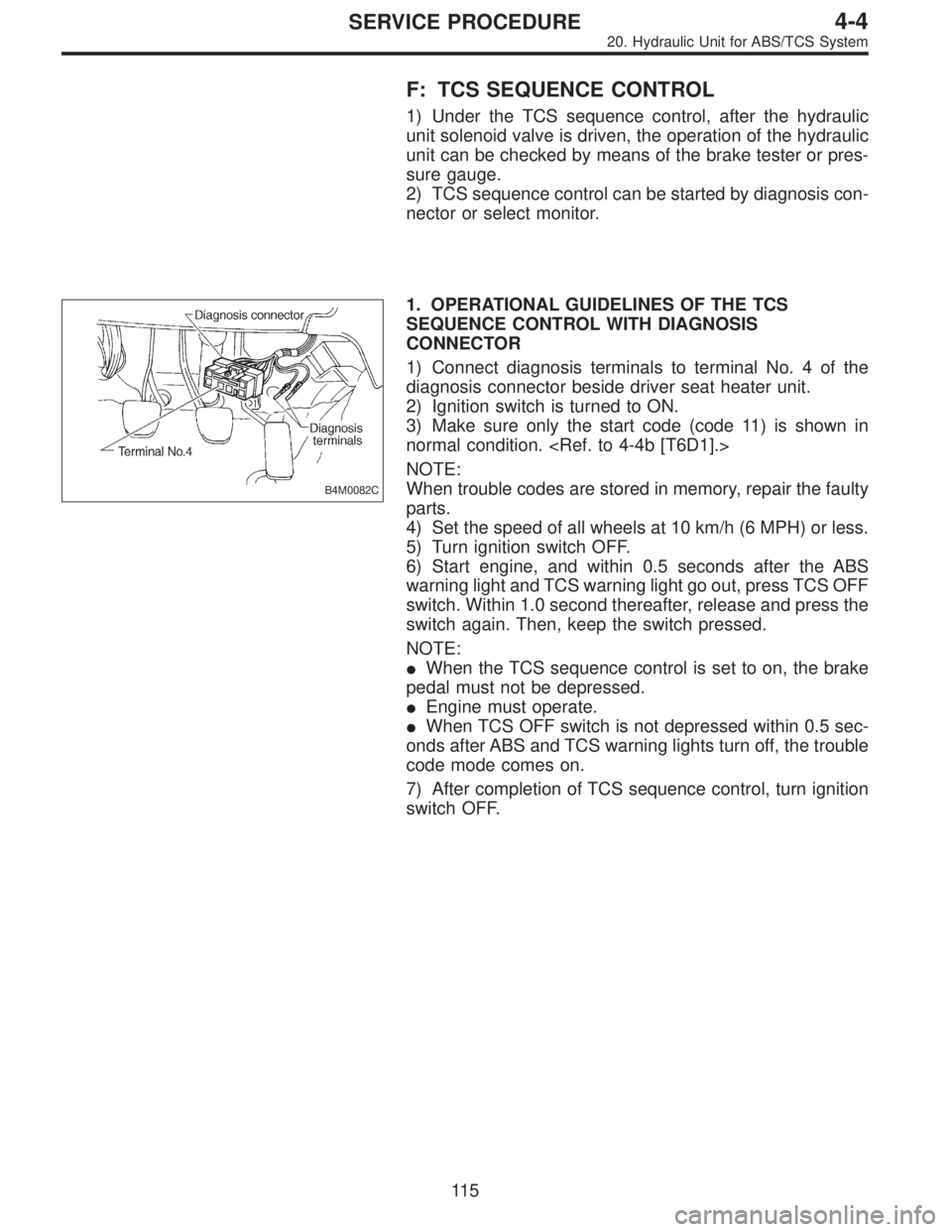
B4M0082C
1. OPERATIONAL GUIDELINES OF THE TCS
SEQUENCE CONTROL WITH DIAGNOSIS
CONNECTOR
1) Connect diagnosis terminals to terminal No. 4 of the
diagnosis connector beside driver seat heater unit.
2) Ignition switch is turned to ON.
3) Make sure only the start code (code 11) is shown in
normal condition.
NOTE:
When trouble codes are stored in memory, repair the faulty
parts.
4) Set the speed of all wheels at 10 km/h (6 MPH) or less.
5) Turn ignition switch OFF.
6) Start engine, and within 0.5 seconds after the ABS
warning light and TCS warning light go out, press TCS OFF
switch. Within 1.0 second thereafter, release and press the
switch again. Then, keep the switch pressed.
NOTE:
�When the TCS sequence control is set to on, the brake
pedal must not be depressed.
�Engine must operate.
�When TCS OFF switch is not depressed within 0.5 sec-
onds after ABS and TCS warning lights turn off, the trouble
code mode comes on.
7) After completion of TCS sequence control, turn ignition
switch OFF.
11 5
4-4SERVICE PROCEDURE
20. Hydraulic Unit for ABS/TCS System
Page 1400 of 3342
2. OPERATIONAL GUIDELINES OF THE TCS
SEQUENCE CONTROL WITH SELECT MONITOR
1) Connect select monitor to data link connector beside
driver’s seat heater unit.
2) Engine starts.
3) Put select monitor to TCS mode.
4) Put select monitor to FBI mode. Make sure code 11 is
indicated.
NOTE:
When trouble codes are stored in memory, repair the faulty
parts.
B4M0639
5) Press FD2 ENT key.
B4M0624
6) When the message shown in the figure is displayed,
press ENT key.
7) Checked portions will be displayed on select monitor.
B4M0627
8) When TCS sequence control cannot be started (by sys-
tem malfunction, etc.), the message shown in the figure will
be displayed.
NOTE:
Read the trouble codes. Repair faulty parts.
11 6
4-4SERVICE PROCEDURE
20. Hydraulic Unit for ABS/TCS System
Page 1410 of 3342
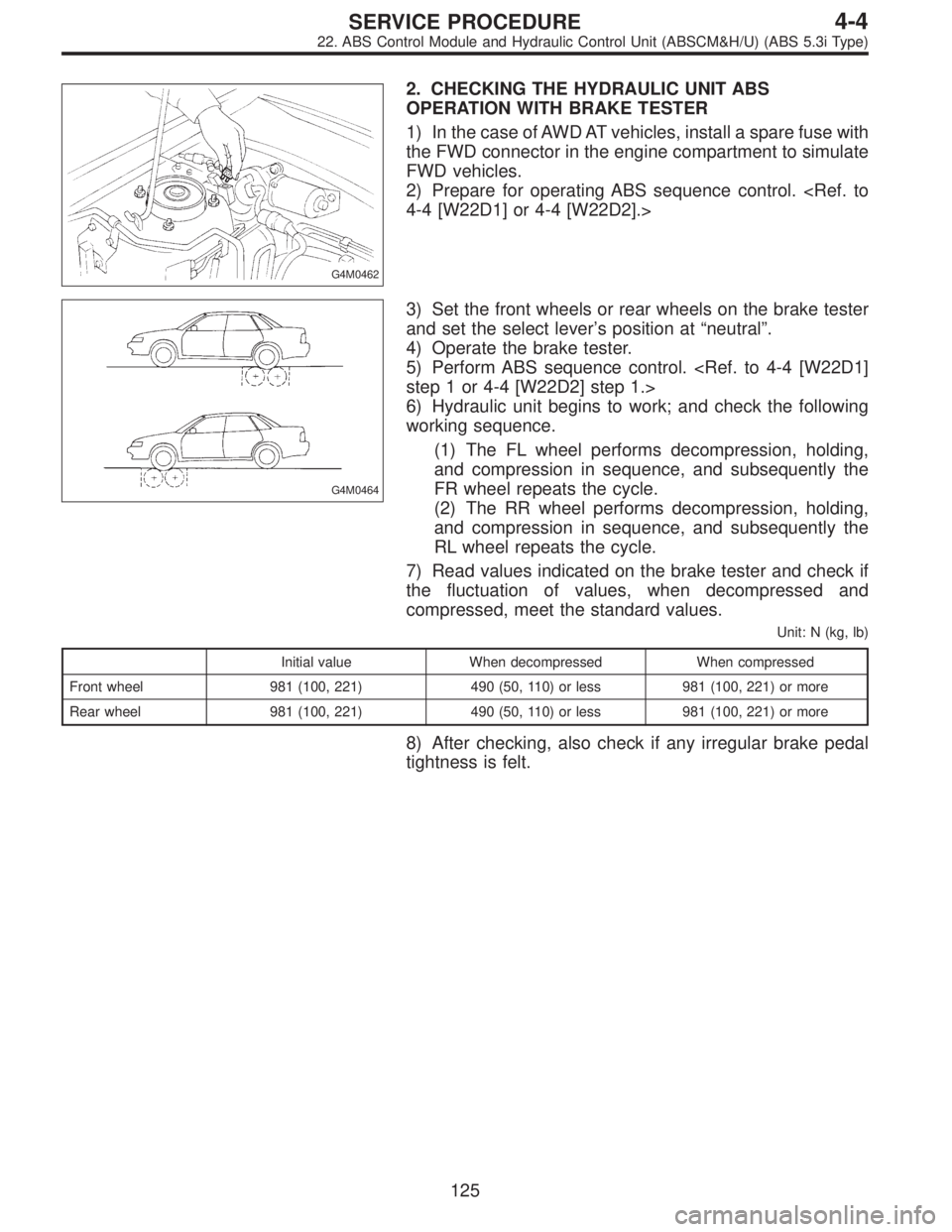
G4M0462
2. CHECKING THE HYDRAULIC UNIT ABS
OPERATION WITH BRAKE TESTER
1) In the case of AWD AT vehicles, install a spare fuse with
the FWD connector in the engine compartment to simulate
FWD vehicles.
2) Prepare for operating ABS sequence control.
4-4 [W22D1] or 4-4 [W22D2].>
G4M0464
3) Set the front wheels or rear wheels on the brake tester
and set the select lever’s position at“neutral”.
4) Operate the brake tester.
5) Perform ABS sequence control.
step 1 or 4-4 [W22D2] step 1.>
6) Hydraulic unit begins to work; and check the following
working sequence.
(1) The FL wheel performs decompression, holding,
and compression in sequence, and subsequently the
FR wheel repeats the cycle.
(2) The RR wheel performs decompression, holding,
and compression in sequence, and subsequently the
RL wheel repeats the cycle.
7) Read values indicated on the brake tester and check if
the fluctuation of values, when decompressed and
compressed, meet the standard values.
Unit: N (kg, lb)
Initial value When decompressed When compressed
Front wheel 981 (100, 221) 490 (50, 110) or less 981 (100, 221) or more
Rear wheel 981 (100, 221) 490 (50, 110) or less 981 (100, 221) or more
8) After checking, also check if any irregular brake pedal
tightness is felt.
125
4-4SERVICE PROCEDURE
22. ABS Control Module and Hydraulic Control Unit (ABSCM&H/U) (ABS 5.3i Type)
Page 1411 of 3342
D: ABS SEQUENCE CONTROL
1) Under the ABS sequence control, after the hydraulic
unit solenoid valve is driven, the operation of the hydraulic
unit can be checked by means of the brake tester or pres-
sure gauge.
2) ABS sequence control can be started by diagnosis con-
nector or select monitor.
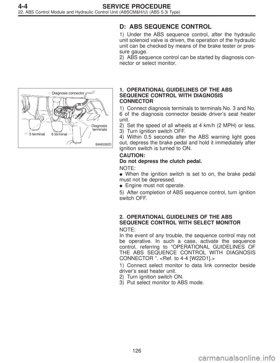
B4M0082D
1. OPERATIONAL GUIDELINES OF THE ABS
SEQUENCE CONTROL WITH DIAGNOSIS
CONNECTOR
1) Connect diagnosis terminals to terminals No. 3 and No.
6 of the diagnosis connector beside driver’s seat heater
unit.
2) Set the speed of all wheels at 4 km/h (2 MPH) or less.
3) Turn ignition switch OFF.
4) Within 0.5 seconds after the ABS warning light goes
out, depress the brake pedal and hold it immediately after
ignition switch is turned to ON.
CAUTION:
Do not depress the clutch pedal.
NOTE:
�When the ignition switch is set to on, the brake pedal
must not be depressed.
�Engine must not operate.
5) After completion of ABS sequence control, turn ignition
switch OFF.
2. OPERATIONAL GUIDELINES OF THE ABS
SEQUENCE CONTROL WITH SELECT MONITOR
NOTE:
In the event of any trouble, the sequence control may not
be operative. In such a case, activate the sequence
control, referring to“OPERATIONAL GUIDELINES OF
THE ABS SEQUENCE CONTROL WITH DIAGNOSIS
CONNECTOR”.
1) Connect select monitor to data link connector beside
driver’s seat heater unit.
2) Turn ignition switch ON.
3) Put select monitor to ABS mode.
126
4-4SERVICE PROCEDURE
22. ABS Control Module and Hydraulic Control Unit (ABSCM&H/U) (ABS 5.3i Type)
Page 1427 of 3342
G4M0319
2) If it is not in specified value, adjust it by turning adjust-
ing nut on engine side end of clutch cable.
Free play: L
3—4 mm (0.12—0.16 in)
Full stroke: A
25.5—27 mm (1.004—1.063 in)
3) Apply grease to connecting portion of clutch pedal and
clutch cable.
�
1Lock nut
�
2Adjusting nut
�
3Release fork
Lock nut tightening torque:
5.9±1.5 N⋅m (0.60±0.15 kg-m, 4.3±1.1 ft-lb)
G4M0320
3. ACCELERATOR PEDAL
Check pedal stroke and free play by operating accelerator
pedal by hand.
If it is not within specified value, adjust it by turning nut
connecting accelerator cable to throttle body.
Free play at pedal pad: L
1—4 mm (0.04—0.16 in)
Stroke at pedal pad: A
50—55 mm (1.97—2.17 in)
�
1Accelerator pedal
�
2Toe board
�
3Accelerator cable
Accelerator cable lock nut tightening torque:
14±4 N⋅m (1.4±0.4 kg-m, 10.1±2.9 ft-lb)
8
4-5SERVICE PROCEDURE
1. Pedal
Page 1428 of 3342
B4M1191A
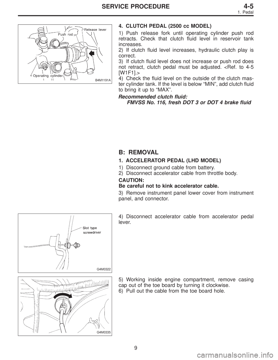
4. CLUTCH PEDAL (2500 cc MODEL)
1) Push release fork until operating cylinder push rod
retracts. Check that clutch fluid level in reservoir tank
increases.
2) If clutch fluid level increases, hydraulic clutch play is
correct.
3) If clutch fluid level does not increase or push rod does
not retract, clutch pedal must be adjusted.
[W1F1].>
4) Check the fluid level on the outside of the clutch mas-
ter cylinder tank. If the level is below“MIN”, add clutch fluid
to bring it up to“MAX”.
Recommended clutch fluid:
FMVSS No. 116, fresh DOT 3 or DOT 4 brake fluid
B: REMOVAL
1. ACCELERATOR PEDAL (LHD MODEL)
1) Disconnect ground cable from battery.
2) Disconnect accelerator cable from throttle body.
CAUTION:
Be careful not to kink accelerator cable.
3) Remove instrument panel lower cover from instrument
panel, and connector.
G4M0322
4) Disconnect accelerator cable from accelerator pedal
lever.
G4M0335
5) Working inside engine compartment, remove casing
cap out of the toe board by turning it clockwise.
6) Pull out the cable from the toe board hole.
9
4-5SERVICE PROCEDURE
1. Pedal
Page 1434 of 3342
G4M0330
E: INSTALLATION
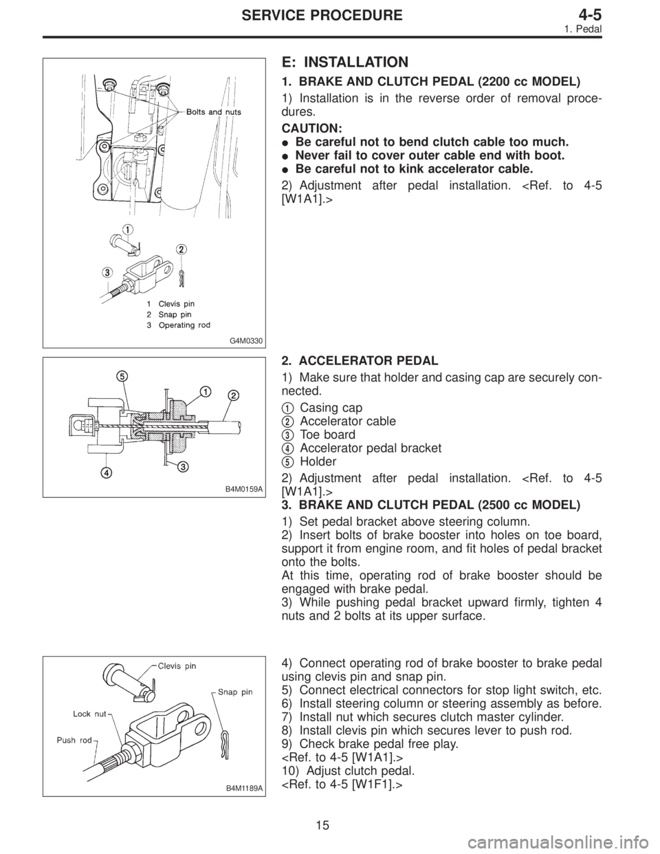
1. BRAKE AND CLUTCH PEDAL (2200 cc MODEL)
1) Installation is in the reverse order of removal proce-
dures.
CAUTION:
�Be careful not to bend clutch cable too much.
�Never fail to cover outer cable end with boot.
�Be careful not to kink accelerator cable.
2) Adjustment after pedal installation.
[W1A1].>
B4M0159A
2. ACCELERATOR PEDAL
1) Make sure that holder and casing cap are securely con-
nected.
�
1Casing cap
�
2Accelerator cable
�
3Toe board
�
4Accelerator pedal bracket
�
5Holder
2) Adjustment after pedal installation.
[W1A1].>
3. BRAKE AND CLUTCH PEDAL (2500 cc MODEL)
1) Set pedal bracket above steering column.
2) Insert bolts of brake booster into holes on toe board,
support it from engine room, and fit holes of pedal bracket
onto the bolts.
At this time, operating rod of brake booster should be
engaged with brake pedal.
3) While pushing pedal bracket upward firmly, tighten 4
nuts and 2 bolts at its upper surface.
B4M1189A
4) Connect operating rod of brake booster to brake pedal
using clevis pin and snap pin.
5) Connect electrical connectors for stop light switch, etc.
6) Install steering column or steering assembly as before.
7) Install nut which secures clutch master cylinder.
8) Install clevis pin which secures lever to push rod.
9) Check brake pedal free play.
10) Adjust clutch pedal.
15
4-5SERVICE PROCEDURE
1. Pedal