Page 1719 of 3342

NGK: BKR6E-11
NIPPONDENSO: K20PR-U1")
3. Spark Plug
A: REMOVAL AND INSTALLATION
CAUTION:
All spark plugs installed on an engine, must be of the
same heat range.
Spark plug:
CHAMPION: RC10YC4
(Alternate)
NGK: BKR6E-11
NIPPONDENSO: K20PR-U11
1) Remove spark plug cords by pulling boot, not cord itself.
2) Remove spark plugs.
3) When installing spark plugs on cylinder head, use spark
plug wrench.
Tightening torque (Spark plug):
20.6±2.9 N⋅m (2.10±0.30 kg-m, 15.19±2.14 ft-lb)
CAUTION:
The above torque should be only applied to new spark
plugs without oil on their threads.
In case their threads are lubricated, the torque should
be reduced by approximately 1/3 of the specified
torque in order to avoid their over-stressing.
4) Connect spark plug cords.
G6M0086
B: INSPECTION
Check electrodes and inner and outer porcelain of plugs,
noting the type of deposits and the degree of electrode
erosion.
G6M0087
1) Normal
Brown to grayish-tan deposits and slight electrode wear
indicate correct spark plug heat range.
23
6-1SERVICE PROCEDURE
3. Spark Plug
Page 1736 of 3342
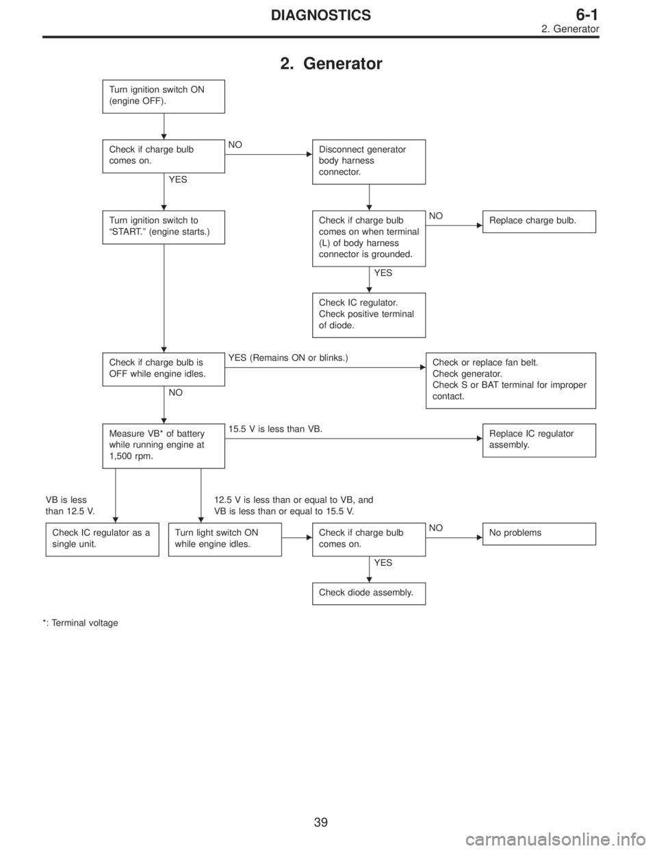
2. Generator
Turn ignition switch ON
(engine OFF).
Check if charge bulb
comes on.
YES
�NO
Disconnect generator
body harness
connector.
Turn ignition switch to
“START.”(engine starts.)Check if charge bulb
comes on when terminal
(L) of body harness
connector is grounded.
YES
�NO
Replace charge bulb.
Check IC regulator.
Check positive terminal
of diode.
Check if charge bulb is
OFF while engine idles.
NO
�YES (Remains ON or blinks.)
Check or replace fan belt.
Check generator.
Check S or BAT terminal for improper
contact.
Measure VB* of battery
while running engine at
1,500 rpm.�15.5 V is less than VB.
Replace IC regulator
assembly.
VB is less
than 12.5 V.12.5 V is less than or equal to VB, and
VB is less than or equal to 15.5 V.
Check IC regulator as a
single unit.
Turn light switch ON
while engine idles.�Check if charge bulb
comes on.
YES
�NO
No problems
Check diode assembly.
*: Terminal voltage
�
��
�
�
�
��
�
39
6-1DIAGNOSTICS
2. Generator
Page 1737 of 3342
, 100 minutes (AT)
Cold cranking ampere 430 amperes (MT), 490 amperes (AT)
Fuse10 A, 15 A, 20 A
Combination
meterSpeedometer")
1. Body Electrical
A: SPECIFICATIONS
BatteryReserve capacity 82 minutes (MT), 100 minutes (AT)
Cold cranking ampere 430 amperes (MT), 490 amperes (AT)
Fuse10 A, 15 A, 20 A
Combination
meterSpeedometer Electric pulse type
Tachometer Electric impulse type
Water temperature gauge Thermistor cross coil type
Fuel gauge Resistance cross coil type
Charge indicator light 12 V—1.4 W
Brake fluid level warning/parking brake indicator light 12 V—1.4 W
AT oil temperature warning light (AWD only) 12 V—1.4 W
ABS warning light 12 V—1.4 W
CHECK ENGINE warning light
(Malfunction indicator lamp)12 V—1.4 W
Oil pressure warning light 12 V—1.4 W
AIRBAG system warning light 12 V—1.4 W
Low fuel warning light 12 V—3W
FWD indicator light 12 V—1.4 W
TCS warning light 12 V—1.4 W
TCS indicator light 12 V—1.4 W
Turn signal indicator light 12 V—1.4 W (2 pieces)
Seat belt warning light 12 V—1.4 W
Door open warning light 12 V—1.4 W (5 pieces)
Headlight beam indicator light 12 V—1.4 W
Meter illumination light12 V—3 W (2 pieces)
12 V—3.4 W (4 pieces)
Headlight 12 V—60/55 W (Halogen)
Front clearance light 12 V—5W
Turn signal lightFront 12 V—21 W
Rear 12 V—21 W
Tail/Stop light 12 V—5/21 W
Back-up light 12 V—21 W
High-mount stop light12 V—18 W (SEDAN), 12 V—13 W
(WAGON)
License plate light 12 V—5W
Room light 12 V—8W
Trunk room light (SEDAN) 12 V—5W
Luggage room light (WAGON) 12 V—5W
Spot light 12 V—8 W (2 pieces)
Glove box light 12 V—3.4 W
Ash tray illumination light 12 V—1.7 W
Selector lever illumination light (AT model) 12 V—1.7 W
2
6-2SPECIFICATIONS
1. Body Electrical
Page 1773 of 3342

B6M0119
B: INSPECTION
1. DEFOGGER SWITCH
Move rear window defogger switch to each position and
check continuity between terminals as indicated in table
below:
Terminal
Switch position35 14 2
OFF�
�
ON�����
G6M0112
2. DEFOGGER RELAY
Check continuity between terminals as indicated in table
below, when connecting the battery to terminal No. 1 and
No. 3.
When current flows.Between terminals
No. 2 and No. 4Continuity exists.
When current does not flow.Between terminals
No. 2 and No. 4Continuity does not
exist.
Between terminals
No. 1 and No. 3Continuity exists.
G6M0135
3. HEAT WIRES
1) Start the engine so that battery is being charged.
2) Turn defogger switch to ON.
3) Check each heat wire at its center position for discon-
tinuity by setting direct current voltmeter.
Normal indication is about 6 volts.
G6M0136
NOTE:
When measuring voltage, wind a piece of tin foil around the
tip of the tester probe and press the foil against the wire
with your finger.
32
6-2SERVICE PROCEDURE
12. Rear Window Defogger
Page 1776 of 3342
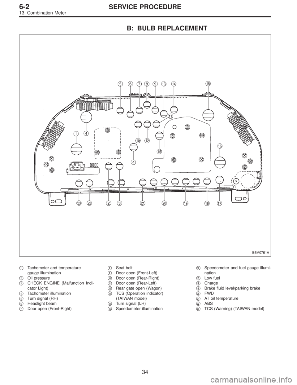
B: BULB REPLACEMENT
B6M0761A
�1Tachometer and temperature
gauge illumination
�
2Oil pressure
�
3CHECK ENGINE (Malfunction Indi-
cator Light)
�
4Tachometer illumination
�
5Turn signal (RH)
�
6Headlight beam
�
7Door open (Front-Right)�
8Seat belt
�
9Door open (Front-Left)
�
10Door open (Rear-Right)
�
11Door open (Rear-Left)
�
12Rear gate open (Wagon)
�
13TCS (Operation indicator)
(TAIWAN model)
�
14Turn signal (LH)
�
15Speedometer illumination�
16Speedometer and fuel gauge illumi-
nation
�
17Low fuel
�
18Charge
�
19Brake fluid level/parking brake
�
20FWD
�
21AT oil temperature
�
22ABS
�
23TCS (Warning) (TAIWAN model)
34
6-2SERVICE PROCEDURE
13. Combination Meter
Page 1802 of 3342
 Disconnect connector of starter interrupt relay.
2) Connect battery to terminal No.1 and ground terminal
No. 2.
3) Check continuity between termina")
B6M0375A
B: INSPECTION
1. STARTER INTERRUPT RELAY
1) Disconnect connector of starter interrupt relay.
2) Connect battery to terminal No.1 and ground terminal
No. 2.
3) Check continuity between terminals as indicated in
table below:
When current flows. Between terminals
No. 3 and No. 5Continuity does not
exist.
When current does not flow. Between terminals
No. 3 and No. 5Continuity exists.
Between terminals
No. 1 and No. 2Continuity exists.
G6M0134
2. HEADLIGHT ALARM RELAY
1) Disconnect connector of headlight alarm relay.
2) Connect battery to terminal No. 1 and ground terminal
No. 2.
3) Check continuity between terminals as indicated in
table below:
When current flows. Between terminals
No. 3 and No. 5Continuity does not
exist.
Between terminals
No. 3 and No. 4Continuity exists.
When current does not flow. Between terminals
No. 3 and No. 5Continuity exists.
Between terminals
No. 3 and No. 4Continuity does not
exist.
Between terminals
No. 1 and No. 2Continuity exists.
B6M0376
3. ENGINE HOOD SWITCH
1) Disconnect connector of engine hood switch.
2) Check continuity between terminals when push rod is
pushed in 1.5 mm (0.059 in) of its stroke.
Terminal
Switch position12
When push rod is
pushed in.
When push rod is
released.��
57
6-2SERVICE PROCEDURE
22. Security System
Page 1806 of 3342
 Fully open all the door windows.
2) Turn the ignition switch to OFF and remove ignition key
from ignition switch.
3) Get out of the vehicle and lock th")
C: FUNCTION TEST
1. SECURITY SYSTEM OPERATION
1) Fully open all the door windows.
2) Turn the ignition switch to OFF and remove ignition key
from ignition switch.
3) Get out of the vehicle and lock the driver’s door using a
ignition key.
4) Check that the security indicator light illuminates.
5) When the security indicator light illuminates, wait for 30
seconds.
After 30 seconds, check that the light starts repeating 0.2
sec. ON and 2.4 sec. OFF sequence.
6) Unlock the driver’s door using the inside lock knob and
open the door.
Ensure that:
(1) the horn sounds and headlights flash intermittently
at 0.2 sec. ON and 0.6 sec. OFF. intervals, and
(2) the engine will not start even if the ignition switch
is turned to START.
7) Unlock the driver’s door one time using the ignition key.
Ensure the horn and headlights turn off.
8) Close and lock the driver’s door without using a ignition
key. (Set the inside lock knob to LOCK and then close the
door while lifting the outer handle).
Check that the security indicator light illuminates continu-
ously.
9) Within 30 seconds after the above step 8), unlock the
rear LH door using the inside lock knob and open the door.
Check that the security indicator light flashes at 0.5 sec.
intervals.
10) Close the rear LH door and lock the door using the
inside lock knob.
Check that the security indicator light illuminates continu-
ously.
11) Perform the above steps 9) and 10) on the rear RH
door and front RH door.
12) Within 30 seconds after above step 11) has been
finished, pull the engine hood opener lever and open the
engine hood.
Check that the security indicator light flashes at 0.5 sec.
intervals.
13) Close the engine hood completely.
Check that the security indicator light illuminates continu-
ously.
61
6-2SERVICE PROCEDURE
22. Security System
Page 1835 of 3342

D: BASIC DIAGNOSTICS PROCEDURE
Start security system check.
Fully open all door windows and turn ignition switch OFF.
Take key out of ignition, exit vehicle and lock driver’s door.
Indicator light illuminates.
OK The light flashes.
� The light does not
illuminate.
Check indicator harness.
Check security indicator light.
Check driver’s door key cylinder lock/unlock switch.
Check security control module.
Check whether switch input signal remains UNLOCK.
Check wiring harness.
Check switch input signals.
(Harnesses and switches separately)
(Tamper, door, hood, trunk and rear gate
switch)Check security control module.
Wait for 30 seconds.
Indicator light flashes at long intervals (0.2 sec. ON and 2.4 sec.
OFF).
OK
� Not OK
Check security control module.
Unlock driver’s door using the inside lock knob and open door.
The horn sounds and headlights flash intermittently at 0.2 sec. ON
and 0.6 sec. OFF intervals.
The engine will not start even if the ignition switch is turned to
START. Indicator lamp goes out.
OK Starter motor runs.
� All are not OK.
Check driver’s door switch.
Check wiring harness.
Check security control module.
� Horn is not OK.
Check horn
operation by
pushing horn pad
on steering wheel.
OK
� Not OK
Check horn.
Check horn relay.
Check security control module.
Check harness between horn relay and security control module.
� Headlights are not
OK.
Check headlights
operation by
turning light switch
ON/OFF.
OK
� Not OK
Check headlight
bulbs.
Check combination
switch.
Check headlight
relay.
Check starter interrupt relay.
Check wiring harness.
Check security control module.Check headlight alarm relay.
Check security control module.
Check wiring harness.
The alarm system continues to operate for 150 seconds.
OK Not OK
The horn and
headlights turn off.
The starter motor
does not run.
OK
� Not OK
Check security
control module.
Unlock the driver’s door using ignition key.
Continues to next step.
�
�
�
�
�
�
�
�
�
��
�
��
�
�
90
6-2DIAGNOSTICS
6. Security System