Page 3058 of 3342
B4M0915
10AJ9
CHECK G SENSOR.
1) Remove console box.
2) Remove G sensor from vehicle.
3) Connect connector to G sensor.
4) Connect connector to ABSCM&H/U.
5) Turn ignition switch to ON.
6) Measure voltage between G sensor connector termi-
nals.
Connector & terminal
(P11) No. 2 (+)—No.1(�):
: Is the voltage between 2.1 and 2.5 V when G
sensor is horizontal?
: Go to step10AJ10.
: Replace G sensor.
B4M0917A
10AJ10
CHECK G SENSOR.
Measure voltage between G sensor connector terminals.
Connector & terminal
(P11) No. 2 (+)—No.1(�):
: Is the voltage between 3.7 and 4.1 V when G
sensor is inclined forwards to 90°?
: Go to step10AJ11.
: Replace G sensor.
B4M0918A
10AJ11
CHECK G SENSOR.
Measure voltage between G sensor connector terminals.
Connector & terminal
(P11) No. 2 (+)—No.1(�):
: Is the voltage between 0.5 and 0.9 V when G
sensor is inclined backwards to 90°?
: Go to step10AJ12.
: Replace G sensor.
182
4-4dBRAKES [ABS 5.3i TYPE]
10. Diagnostics Chart with Select Monitor
Page 3059 of 3342
10AJ12
CHECK ABSCM&H/U.
1) Turn ignition switch to OFF.
2) Connect all connectors.
3) Erase the memory.
4) Perform inspection mode.
5) Read out the trouble code.
: Is the same trouble code as in the current
diagnosis still being output?
: Replace ABSCM&H/U.
: Go to step10AJ13.
10AJ13CHECK ANY OTHER TROUBLE CODES
APPEARANCE.
: Are other trouble codes being output?
: Proceed with the diagnosis corresponding to the
trouble code.
: A temporary poor contact.
183
4-4dBRAKES [ABS 5.3i TYPE]
10. Diagnostics Chart with Select Monitor
Page 3060 of 3342

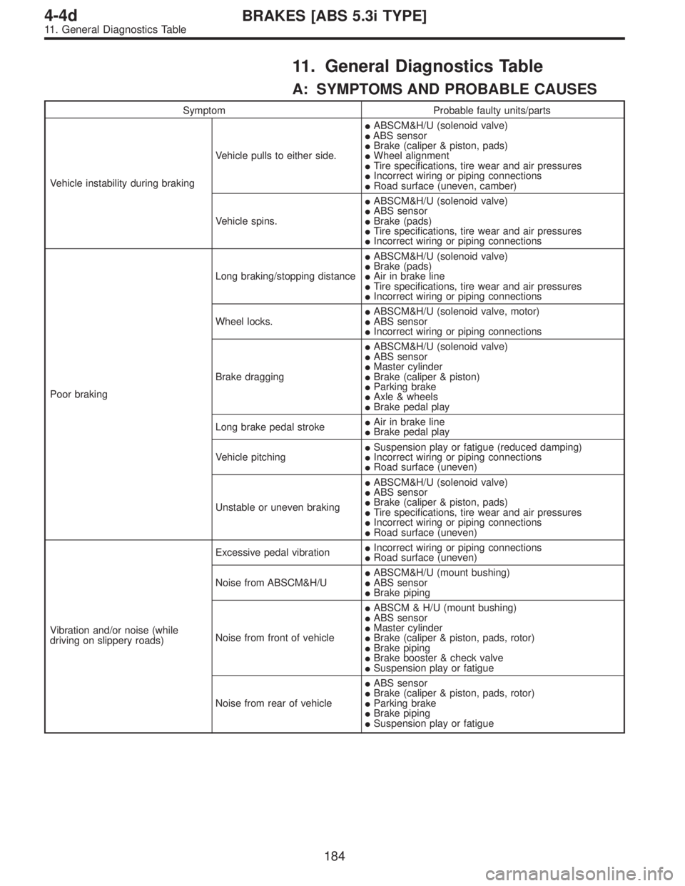
11. General Diagnostics Table
A: SYMPTOMS AND PROBABLE CAUSES
Symptom Probable faulty units/parts
Vehicle instability during brakingVehicle pulls to either side.�ABSCM&H/U (solenoid valve)
�ABS sensor
�Brake (caliper & piston, pads)
�Wheel alignment
�Tire specifications, tire wear and air pressures
�Incorrect wiring or piping connections
�Road surface (uneven, camber)
Vehicle spins.�ABSCM&H/U (solenoid valve)
�ABS sensor
�Brake (pads)
�Tire specifications, tire wear and air pressures
�Incorrect wiring or piping connections
Poor brakingLong braking/stopping distance�ABSCM&H/U (solenoid valve)
�Brake (pads)
�Air in brake line
�Tire specifications, tire wear and air pressures
�Incorrect wiring or piping connections
Wheel locks.�ABSCM&H/U (solenoid valve, motor)
�ABS sensor
�Incorrect wiring or piping connections
Brake dragging�ABSCM&H/U (solenoid valve)
�ABS sensor
�Master cylinder
�Brake (caliper & piston)
�Parking brake
�Axle & wheels
�Brake pedal play
Long brake pedal stroke�Air in brake line
�Brake pedal play
Vehicle pitching�Suspension play or fatigue (reduced damping)
�Incorrect wiring or piping connections
�Road surface (uneven)
Unstable or uneven braking�ABSCM&H/U (solenoid valve)
�ABS sensor
�Brake (caliper & piston, pads)
�Tire specifications, tire wear and air pressures
�Incorrect wiring or piping connections
�Road surface (uneven)
Vibration and/or noise (while
driving on slippery roads)Excessive pedal vibration�Incorrect wiring or piping connections
�Road surface (uneven)
Noise from ABSCM&H/U�ABSCM&H/U (mount bushing)
�ABS sensor
�Brake piping
Noise from front of vehicle�ABSCM & H/U (mount bushing)
�ABS sensor
�Master cylinder
�Brake (caliper & piston, pads, rotor)
�Brake piping
�Brake booster & check valve
�Suspension play or fatigue
Noise from rear of vehicle�ABS sensor
�Brake (caliper & piston, pads, rotor)
�Parking brake
�Brake piping
�Suspension play or fatigue
184
4-4dBRAKES [ABS 5.3i TYPE]
11. General Diagnostics Table
Page 3061 of 3342
B: CHECKING THE HYDRAULIC UNIT
OPERATION
11B1
PREPARING THE BRAKE TESTER.
: Is the brake tester available?
: CHECKING THE HYDRAULIC UNIT ABS
OPERATION WITH BRAKE TESTER
[W20C2].>
: CHECKING THE HYDRAULIC UNIT ABS
OPERATION BY PRESSURE GAUGE
4-4 [W20C1].>
185
4-4dBRAKES [ABS 5.3i TYPE]
11. General Diagnostics Table
Page 3199 of 3342

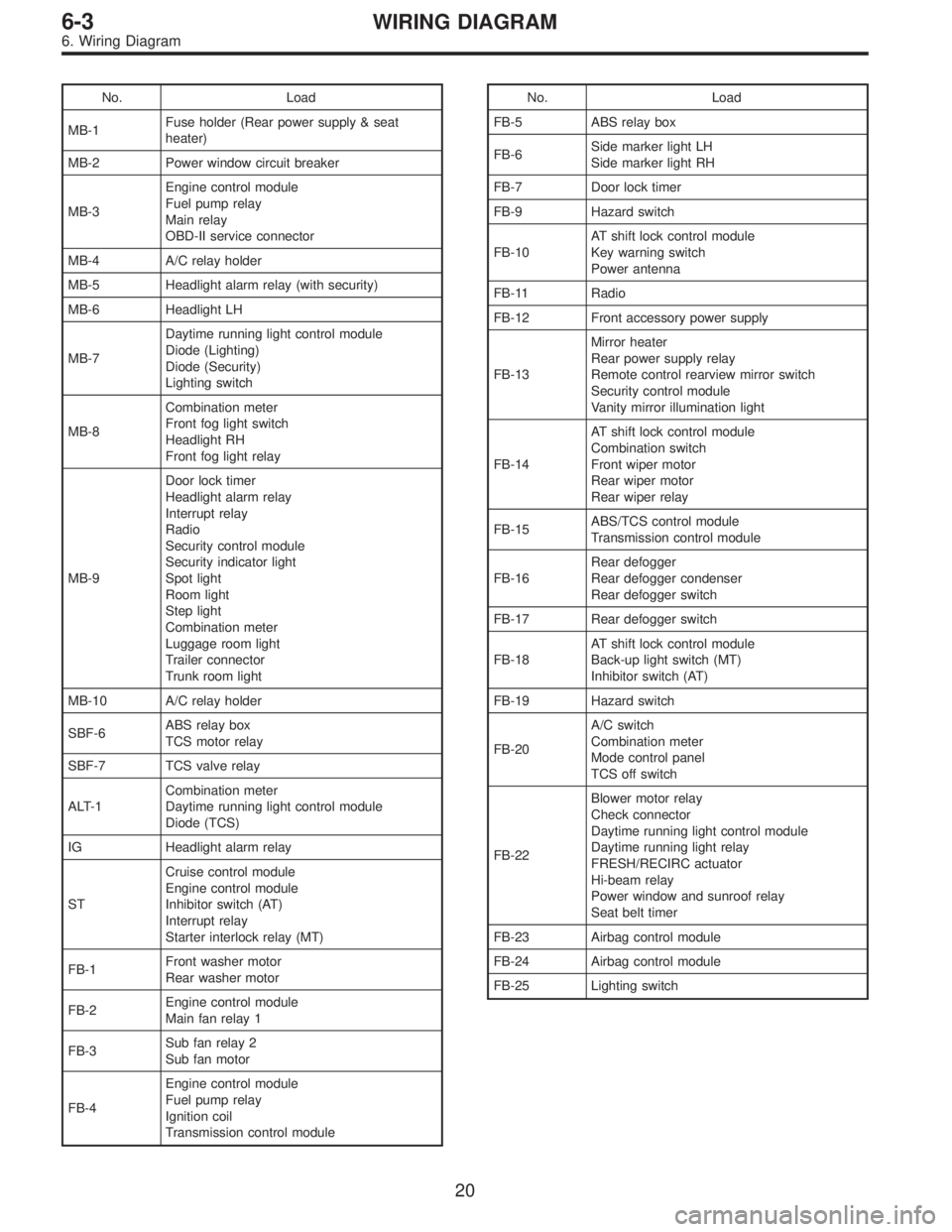
No. Load
MB-1Fuse holder (Rear power supply & seat
heater)
MB-2 Power window circuit breaker
MB-3Engine control module
Fuel pump relay
Main relay
OBD-II service connector
MB-4 A/C relay holder
MB-5 Headlight alarm relay (with security)
MB-6 Headlight LH
MB-7Daytime running light control module
Diode (Lighting)
Diode (Security)
Lighting switch
MB-8Combination meter
Front fog light switch
Headlight RH
Front fog light relay
MB-9Door lock timer
Headlight alarm relay
Interrupt relay
Radio
Security control module
Security indicator light
Spot light
Room light
Step light
Combination meter
Luggage room light
Trailer connector
Trunk room light
MB-10 A/C relay holder
SBF-6ABS relay box
TCS motor relay
SBF-7 TCS valve relay
ALT-1Combination meter
Daytime running light control module
Diode (TCS)
IG Headlight alarm relay
STCruise control module
Engine control module
Inhibitor switch (AT)
Interrupt relay
Starter interlock relay (MT)
FB-1Front washer motor
Rear washer motor
FB-2Engine control module
Main fan relay 1
FB-3Sub fan relay 2
Sub fan motor
FB-4Engine control module
Fuel pump relay
Ignition coil
Transmission control moduleNo. Load
FB-5 ABS relay box
FB-6Side marker light LH
Side marker light RH
FB-7 Door lock timer
FB-9 Hazard switch
FB-10AT shift lock control module
Key warning switch
Power antenna
FB-11 Radio
FB-12 Front accessory power supply
FB-13Mirror heater
Rear power supply relay
Remote control rearview mirror switch
Security control module
Vanity mirror illumination light
FB-14AT shift lock control module
Combination switch
Front wiper motor
Rear wiper motor
Rear wiper relay
FB-15ABS/TCS control module
Transmission control module
FB-16Rear defogger
Rear defogger condenser
Rear defogger switch
FB-17 Rear defogger switch
FB-18AT shift lock control module
Back-up light switch (MT)
Inhibitor switch (AT)
FB-19 Hazard switch
FB-20A/C switch
Combination meter
Mode control panel
TCS off switch
FB-22Blower motor relay
Check connector
Daytime running light control module
Daytime running light relay
FRESH/RECIRC actuator
Hi-beam relay
Power window and sunroof relay
Seat belt timer
FB-23 Airbag control module
FB-24 Airbag control module
FB-25 Lighting switch
20
6-3WIRING DIAGRAM
6. Wiring Diagram
Page 3200 of 3342
No. Load
FB-26 Parking switch
FB-27 Parking switch
FB-28 Illumination light
FB-29 Illumination light
FB-30Pedal stroke switch
Stop light switch
Stop & brake switch
FB-31 Horn relay
FB-32 Blower motor relay
FB-33 Parking switch
FB-34License plate light
Rear combination light LH
Rear combination light RH
Rear finisher light LH
Rear finisher light RH
FB-35ABS control module
ABS/TCS control module
TCS valve relay
Cruise control main switch
Cruise control module
FB-36 Front fog light relay
FB-37 Main fan relay 1
21
6-3WIRING DIAGRAM
6. Wiring Diagram
Page 3297 of 3342

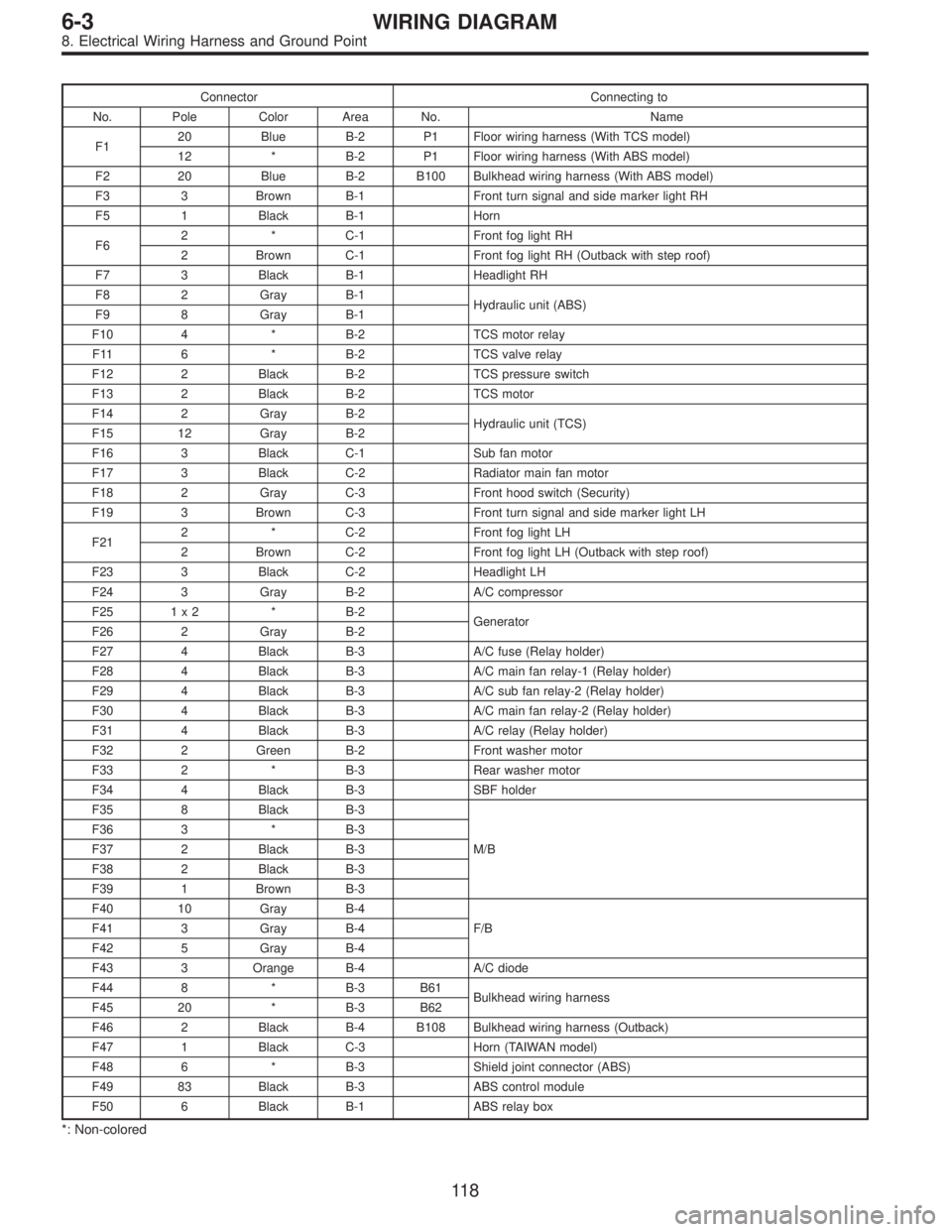
Connector Connecting to
No. Pole Color Area No. Name
F120 Blue B-2 P1 Floor wiring harness (With TCS model)
12 * B-2 P1 Floor wiring harness (With ABS model)
F2 20 Blue B-2 B100 Bulkhead wiring harness (With ABS model)
F3 3 Brown B-1 Front turn signal and side marker light RH
F5 1 Black B-1 Horn
F62 * C-1 Front fog light RH
2 Brown C-1 Front fog light RH (Outback with step roof)
F7 3 Black B-1 Headlight RH
F8 2 Gray B-1
Hydraulic unit (ABS)
F9 8 Gray B-1
F10 4 * B-2 TCS motor relay
F11 6 * B-2 TCS valve relay
F12 2 Black B-2 TCS pressure switch
F13 2 Black B-2 TCS motor
F14 2 Gray B-2
Hydraulic unit (TCS)
F15 12 Gray B-2
F16 3 Black C-1 Sub fan motor
F17 3 Black C-2 Radiator main fan motor
F18 2 Gray C-3 Front hood switch (Security)
F19 3 Brown C-3 Front turn signal and side marker light LH
F212 * C-2 Front fog light LH
2 Brown C-2 Front fog light LH (Outback with step roof)
F23 3 Black C-2 Headlight LH
F24 3 Gray B-2 A/C compressor
F25 1 x 2 * B-2
Generator
F26 2 Gray B-2
F27 4 Black B-3 A/C fuse (Relay holder)
F28 4 Black B-3 A/C main fan relay-1 (Relay holder)
F29 4 Black B-3 A/C sub fan relay-2 (Relay holder)
F30 4 Black B-3 A/C main fan relay-2 (Relay holder)
F31 4 Black B-3 A/C relay (Relay holder)
F32 2 Green B-2 Front washer motor
F33 2 * B-3 Rear washer motor
F34 4 Black B-3 SBF holder
F35 8 Black B-3
M/B F36 3 * B-3
F37 2 Black B-3
F38 2 Black B-3
F39 1 Brown B-3
F40 10 Gray B-4
F/B F41 3 Gray B-4
F42 5 Gray B-4
F43 3 Orange B-4 A/C diode
F44 8 * B-3 B61
Bulkhead wiring harness
F45 20 * B-3 B62
F46 2 Black B-4 B108 Bulkhead wiring harness (Outback)
F47 1 Black C-3 Horn (TAIWAN model)
F48 6 * B-3 Shield joint connector (ABS)
F49 83 Black B-3 ABS control module
F50 6 Black B-1 ABS relay box
*: Non-colored
11 8
6-3WIRING DIAGRAM
8. Electrical Wiring Harness and Ground Point
Page 3301 of 3342

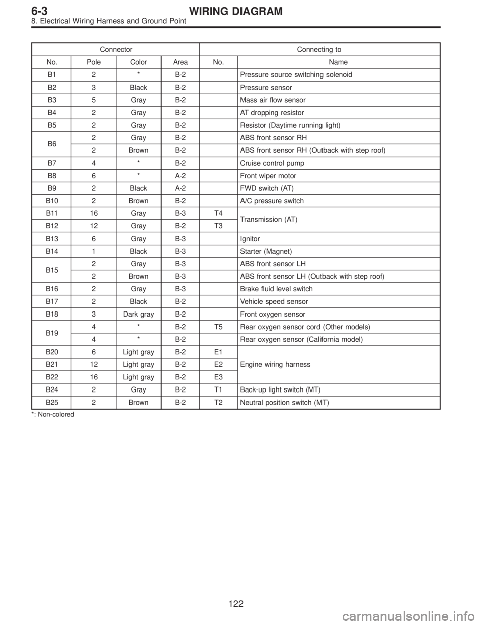
Connector Connecting to
No. Pole Color Area No. Name
B1 2 * B-2 Pressure source switching solenoid
B2 3 Black B-2 Pressure sensor
B3 5 Gray B-2 Mass air flow sensor
B4 2 Gray B-2 AT dropping resistor
B5 2 Gray B-2 Resistor (Daytime running light)
B62 Gray B-2 ABS front sensor RH
2 Brown B-2 ABS front sensor RH (Outback with step roof)
B7 4 * B-2 Cruise control pump
B8 6 * A-2 Front wiper motor
B9 2 Black A-2 FWD switch (AT)
B10 2 Brown B-2 A/C pressure switch
B11 16 Gray B-3 T4
Transmission (AT)
B12 12 Gray B-2 T3
B13 6 Gray B-3 Ignitor
B14 1 Black B-3 Starter (Magnet)
B152 Gray B-3 ABS front sensor LH
2 Brown B-3 ABS front sensor LH (Outback with step roof)
B16 2 Gray B-3 Brake fluid level switch
B17 2 Black B-2 Vehicle speed sensor
B18 3 Dark gray B-2 Front oxygen sensor
B194 * B-2 T5 Rear oxygen sensor cord (Other models)
4 * B-2 Rear oxygen sensor (California model)
B20 6 Light gray B-2 E1
Engine wiring harness B21 12 Light gray B-2 E2
B22 16 Light gray B-2 E3
B24 2 Gray B-2 T1 Back-up light switch (MT)
B25 2 Brown B-2 T2 Neutral position switch (MT)
*: Non-colored
122
6-3WIRING DIAGRAM
8. Electrical Wiring Harness and Ground Point