Page 2970 of 3342
B4M1234A
10C5CHECK POWER SUPPLY OF
ABSCM&H/U.
1) Disconnect connector from ABSCM&H/U.
2) Start engine.
3) Idle the engine.
4) Measure voltage between ABSCM&H/U connector and
chassis ground.
Connector & terminal
(F49) No. 1 (+)—Chassis ground (�):
: Is the voltage between 10 and 15 V?
: Go to step10C6.
: Repair ABSCM&H/U power supply circuit.
B4M1243A
10C6CHECK GROUND CIRCUIT OF
ABSCM&H/U.
1) Turn ignition switch to OFF.
2) Measure resistance between ABSCM&H/U connector
and chassis ground.
Connector & terminal
(F49) No. 23—Chassis ground:
: Is the resistance less than 0.5Ω?
: Repair harness/connector between ABSCM&H/U
and select monitor.
: Go to step10C7.
94
4-4dBRAKES [ABS 5.3i TYPE]
10. Diagnostics Chart with Select Monitor
Page 2971 of 3342
B4M1267A
10C7CHECK HARNESS/CONNECTOR
BETWEEN ABSCM&H/U AND DATA LINK
CONNECTOR.
1) Turn ignition switch OFF.
2) Measure resistance between ABSCM&H/U connector
and data link connector.
Connector & terminal
(F49) No. 20—(B78) No. 3:
(F49) No. 5—(B78) No. 2:
: Is the resistance less than 0.5Ω?
: Repair harness and connector between
ABSCM&H/U and data link connector.
: Go to step10C8.
10C8CHECK POOR CONTACT IN CONNEC-
TORS.
: Is there poor contact in connectors between
ABSCM&H/U and data link connector?
to FOREWORD [T3C1].>
: Repair connector.
: Replace ABSCM&H/U.
95
4-4dBRAKES [ABS 5.3i TYPE]
10. Diagnostics Chart with Select Monitor
Page 2972 of 3342
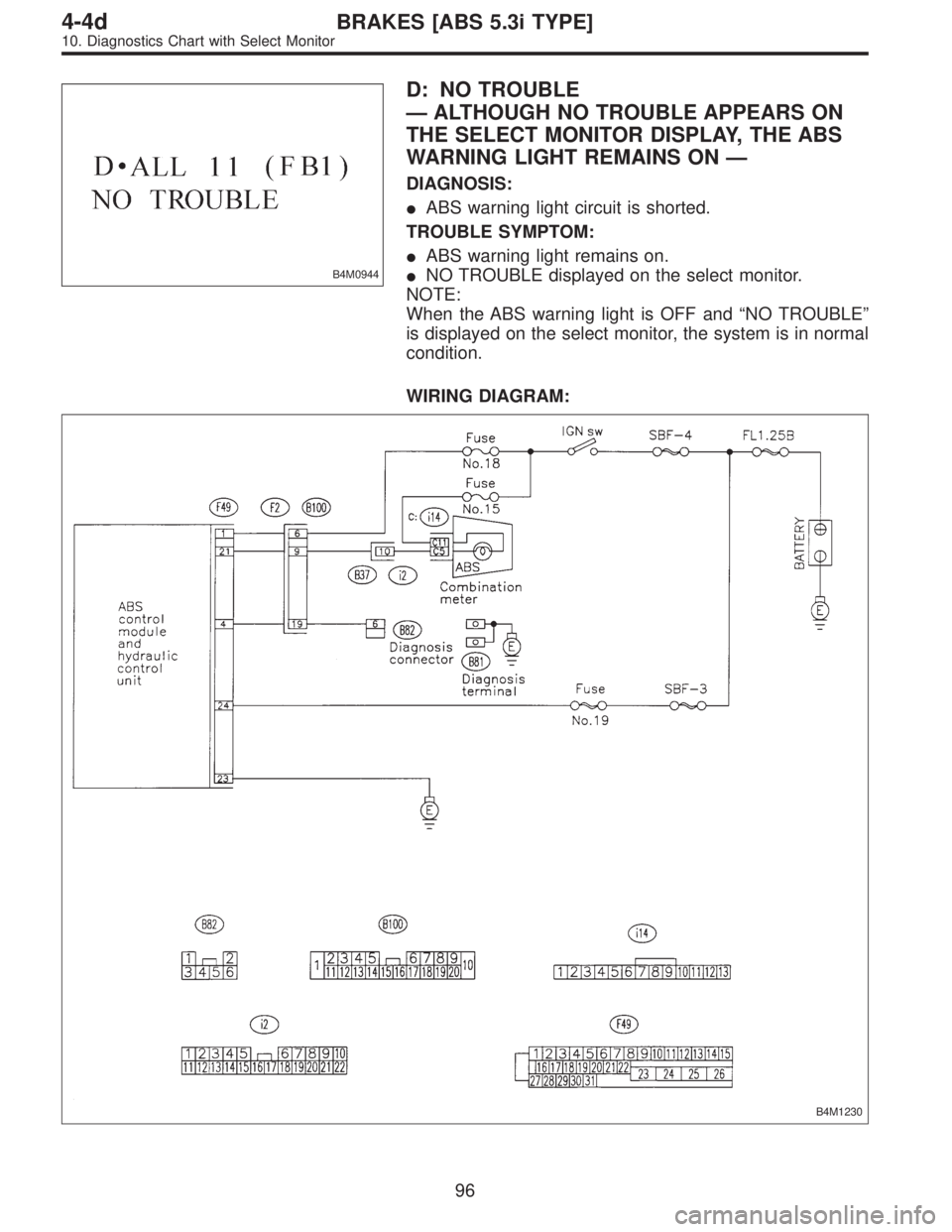
B4M0944
D: NO TROUBLE
—ALTHOUGH NO TROUBLE APPEARS ON
THE SELECT MONITOR DISPLAY, THE ABS
WARNING LIGHT REMAINS ON—
DIAGNOSIS:
�ABS warning light circuit is shorted.
TROUBLE SYMPTOM:
�ABS warning light remains on.
�NO TROUBLE displayed on the select monitor.
NOTE:
When the ABS warning light is OFF and“NO TROUBLE”
is displayed on the select monitor, the system is in normal
condition.
WIRING DIAGRAM:
B4M1230
96
4-4dBRAKES [ABS 5.3i TYPE]
10. Diagnostics Chart with Select Monitor
Page 2973 of 3342
 Turn ignition switch to OFF.
2) Disconnect connector (F2) from connector (B100).
3) Turn ignition switch to ON.
: Does the ABS warning light remain off?
: Go to step10D2.")
10D1
CHECK WIRING HARNESS.
1) Turn ignition switch to OFF.
2) Disconnect connector (F2) from connector (B100).
3) Turn ignition switch to ON.
: Does the ABS warning light remain off?
: Go to step10D2.
: Repair front wiring harness.
B4M1235A
10D2
CHECK PROJECTION AT ABSCM&H/U.
1) Turn ignition switch to OFF.
2) Disconnect connector from ABSCM&H/U.
3) Check for broken projection at the ABSCM&H/U termi-
nal.
: Are the projection broken?
: Go to step10D3.
: Replace ABSCM&H/U.
B4M1237A
10D3
CHECK ABSCM&H/U.
Measure resistance between ABSCM&H/U terminals.
Terminals
No. 21—No. 23:
: Is the resistance more than 1 MΩ?
: Go to step10D4.
: Replace valve relay.
B4M1236A
10D4
CHECK WIRING HARNESS.
Measure resistance between connector (F2) and chassis
ground.
Connector & terminal
(F2) No. 9—Chassis ground:
: Is the resistance less than 0.5Ω?
: Go to step10D5.
: Repair harness.
B4M1236A
10D5
CHECK WIRING HARNESS.
1) Connect connector to ABSCM&H/U.
2) Measure resistance between connector (F2) and chas-
sis ground.
Connector & terminal
(F2) No. 9—Chassis ground:
: Is the resistance more than 1 MΩ?
: Go to step10D6.
: Repair harness.
97
4-4dBRAKES [ABS 5.3i TYPE]
10. Diagnostics Chart with Select Monitor
Page 2974 of 3342
10D6CHECK POOR CONTACT IN ABSCM&H/U
CONNECTOR.
: Is there poor contact in ABSCM&H/U con-
nector?
: Repair connector.
: Replace ABSCM&H/U.
98
4-4dBRAKES [ABS 5.3i TYPE]
10. Diagnostics Chart with Select Monitor
Page 2975 of 3342
B4M0945
E: TROUBLE CODE 21 FR. SS HARD
—ABNORMAL FRONT RH ABS SENSOR
(OPEN CIRCUIT OR INPUT VOLTAGE TOO
HIGH)—
B4M0946
F: TROUBLE CODE 23 FL. SS HARD
—ABNORMAL FRONT LH ABS SENSOR
(OPEN CIRCUIT OR INPUT VOLTAGE TOO
HIGH)—
B4M0947
G: TROUBLE CODE 25 RR. SS HARD
—ABNORMAL REAR RH ABS SENSOR
(OPEN CIRCUIT OR INPUT VOLTAGE TOO
HIGH)—
B4M0948
H: TROUBLE CODE 27 RL. SS HARD
—ABNORMAL REAR LH ABS SENSOR
(OPEN CIRCUIT OR INPUT VOLTAGE TOO
HIGH)—
99
4-4dBRAKES [ABS 5.3i TYPE]
10. Diagnostics Chart with Select Monitor
Page 2976 of 3342
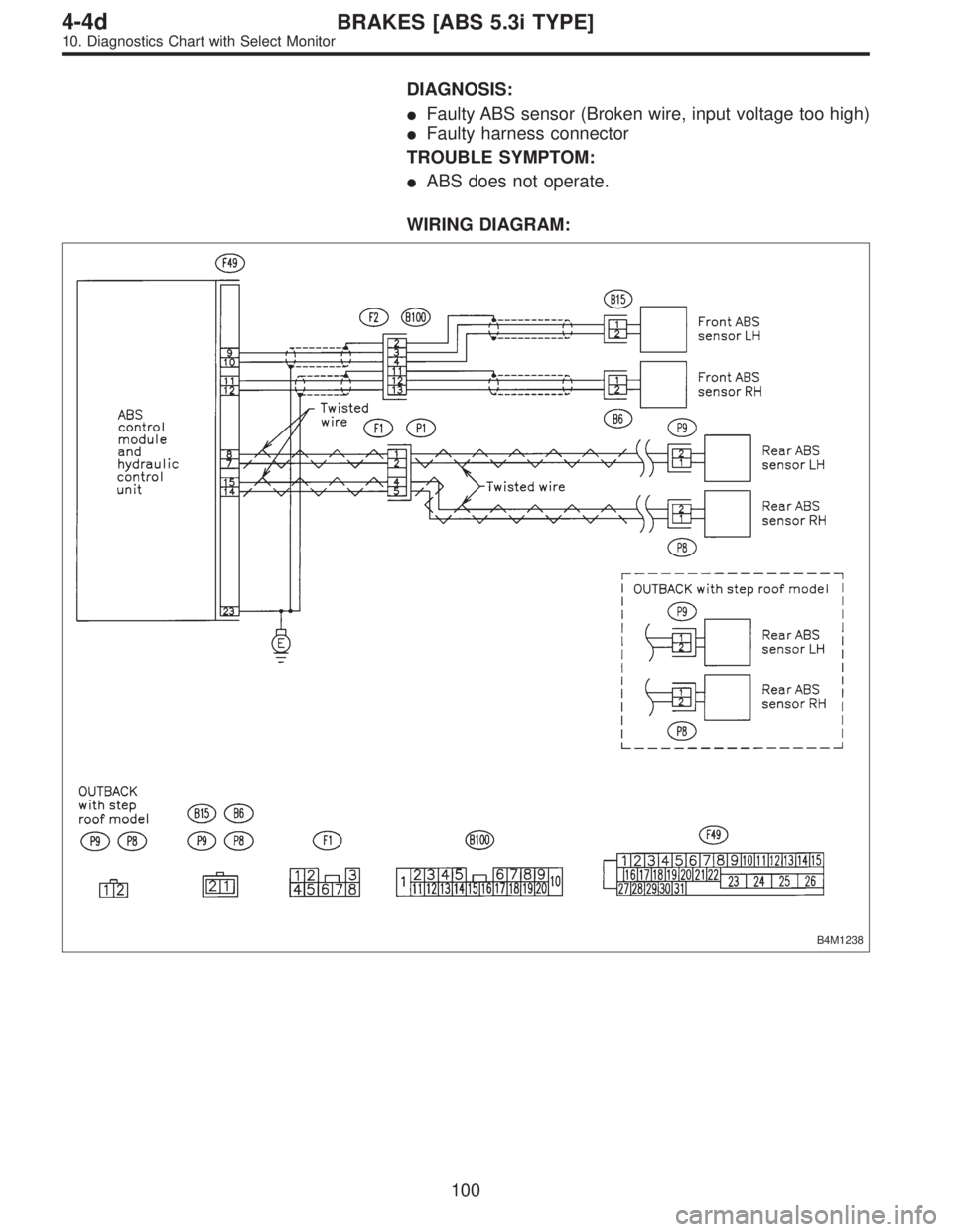
DIAGNOSIS:
�Faulty ABS sensor (Broken wire, input voltage too high)
�Faulty harness connector
TROUBLE SYMPTOM:
�ABS does not operate.
WIRING DIAGRAM:
B4M1238
100
4-4dBRAKES [ABS 5.3i TYPE]
10. Diagnostics Chart with Select Monitor
Page 2977 of 3342

B4M0922
10H1CHECK OUTPUT OF ABS SENSOR
USING SELECT MONITOR.
Read the ABS sensor output corresponding to the faulty
system in the select monitor function mode.
NOTE:
The select monitor display shows that the front right wheel
is rotating at 30 km/h.
: Does the speed indicated on the display
change in response to the speedometer
reading during acceleration/deceleration
when the steering wheel is in the straight-
ahead position?
: Go to step10H2.
: Go to step10H9.
10H2CHECK INSTALLATION OF ABS SEN-
SOR.
Tightening torque:
32±10 N⋅m (3.3±1.0 kg-m, 24±7 ft-lb)
: Are the ABS sensor installation bolts tight-
ened securely?
: Go to step10H3.
: Tighten ABS sensor installation bolts securely.
10H3CHECK INSTALLATION OF TONE
WHEEL.
Tightening torque:
13±3 N⋅m (1.3±0.3 kg-m, 9±2.2 ft-lb)
: Are the tone wheel installation bolts tight-
ened securely?
: Go to step10H4.
: Tighten tone wheel installation bolts securely.
101
4-4dBRAKES [ABS 5.3i TYPE]
10. Diagnostics Chart with Select Monitor
 Disconnect connector from ABSCM&H/U.
2) Start engine.
3) Idle the engine.
4) Measure voltage between ABSCM&H/U connector and
chassis ground.
Connector")
 Turn ignition switch OFF.
2) Measure resistance between ABSCM&H/U connector
and data link connector.
Connector & term")
![SUBARU LEGACY 1997 Service Repair Manual 10D6CHECK POOR CONTACT IN ABSCM&H/U
CONNECTOR.
: Is there poor contact in ABSCM&H/U con-
nector? <Ref. to FOREWORD [T3C1].>
: Repair connector.
: Replace ABSCM&H/U.
98
4-4dBRAKES [ABS 5.3i TYPE]
10. D](/manual-img/17/57434/w960_57434-2973.png "SUBARU LEGACY 1997 Service Repair Manual 10D6CHECK POOR CONTACT IN ABSCM&H/U
CONNECTOR.
: Is there poor contact in ABSCM&H/U con-
nector? <Ref. to FOREWORD [T3C1].>
: Repair connector.
: Replace ABSCM&H/U.
98
4-4dBRAKES [ABS 5.3i TYPE]
10. D")
—
B4M0946
F: TROUBLE CODE 23 FL. SS HARD
—ABNORMAL FRONT LH ABS SENSOR
(OPEN CIRCUIT")