Page 457 of 3342
B2M0323
5) Remove radiator fan motor assembly.
6) Remove fan motor from shroud.
B: INSTALLATION
Installation is in the reverse order of removal procedures.
Do the following:
1) Before installing radiator fan motor, apply a coat of seal-
ant to threads and tighten nuts.
2) Make sure radiator fan does not come into contact with
shroud when installed.
3) After installation, make sure there is no unusual noise
or vibration when fan is rotated.
G6M0095
7. Engine Coolant Pipe
A: REMOVAL
1) Release fuel pressure.
2) Disconnect ground cable from the battery.
B2M0015A
3) Drain engine coolant completely.
B2M0160
4) Remove intake manifold.
17
2-5SERVICE PROCEDURE
6. Radiator Fan and Fan Motor - 7. Engine Coolant Pipe
Page 459 of 3342
B2M0138
3) Connect heater inlet hose.
B2M0160
4) Install intake manifold.
G6M0095
5) Connect ground cable to battery terminal.
19
2-5SERVICE PROCEDURE
7. Engine Coolant Pipe
Page 463 of 3342

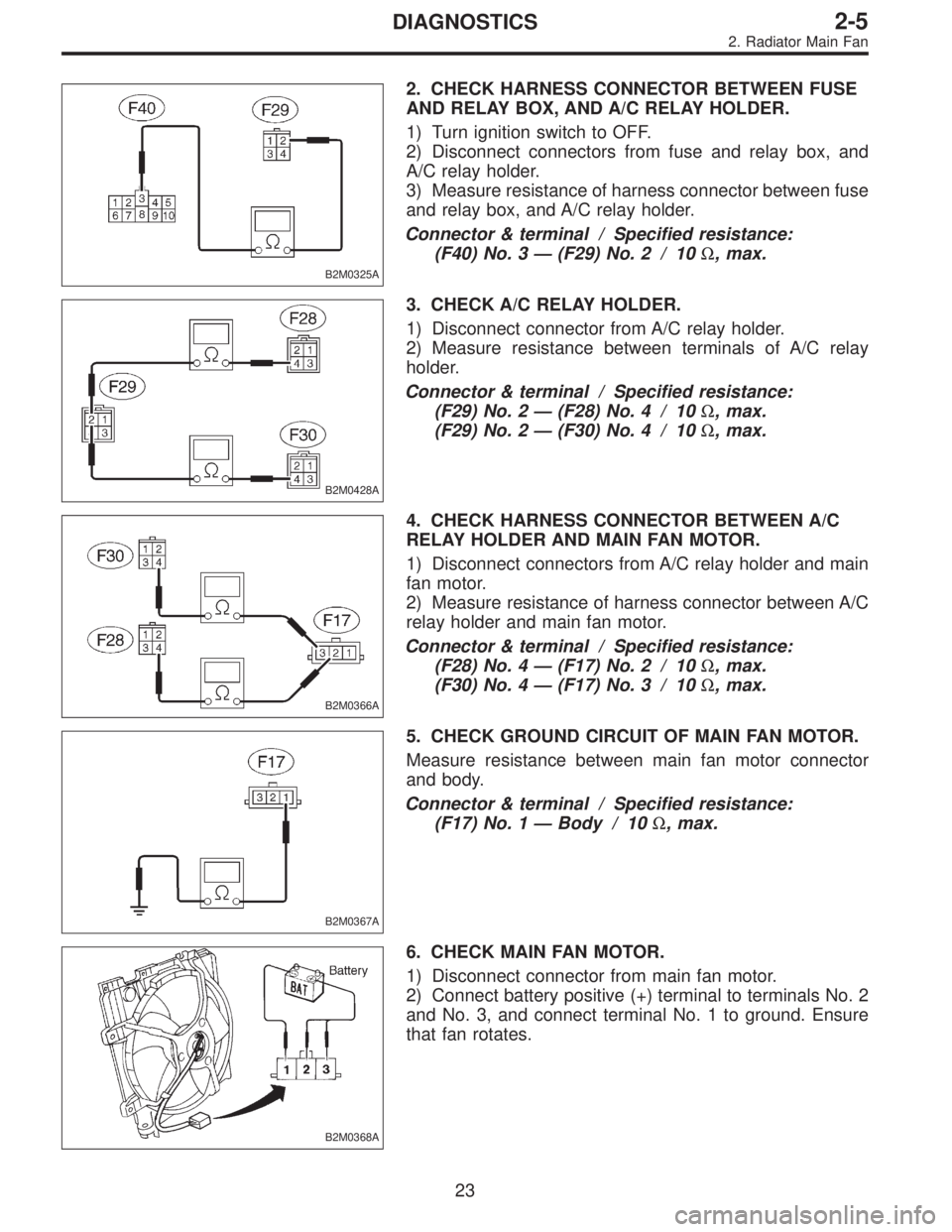
B2M0325A
2. CHECK HARNESS CONNECTOR BETWEEN FUSE
AND RELAY BOX, AND A/C RELAY HOLDER.
1) Turn ignition switch to OFF.
2) Disconnect connectors from fuse and relay box, and
A/C relay holder.
3) Measure resistance of harness connector between fuse
and relay box, and A/C relay holder.
Connector & terminal / Specified resistance:
(F40) No. 3—(F29) No. 2 / 10Ω, max.
B2M0428A
3. CHECK A/C RELAY HOLDER.
1) Disconnect connector from A/C relay holder.
2) Measure resistance between terminals of A/C relay
holder.
Connector & terminal / Specified resistance:
(F29) No. 2—(F28) No. 4 / 10Ω, max.
(F29) No. 2—(F30) No. 4 / 10Ω, max.
B2M0366A
4. CHECK HARNESS CONNECTOR BETWEEN A/C
RELAY HOLDER AND MAIN FAN MOTOR.
1) Disconnect connectors from A/C relay holder and main
fan motor.
2) Measure resistance of harness connector between A/C
relay holder and main fan motor.
Connector & terminal / Specified resistance:
(F28) No. 4—(F17) No. 2 / 10Ω, max.
(F30) No. 4—(F17) No. 3 / 10Ω, max.
B2M0367A
5. CHECK GROUND CIRCUIT OF MAIN FAN MOTOR.
Measure resistance between main fan motor connector
and body.
Connector & terminal / Specified resistance:
(F17) No. 1—Body / 10Ω, max.
B2M0368A
6. CHECK MAIN FAN MOTOR.
1) Disconnect connector from main fan motor.
2) Connect battery positive (+) terminal to terminals No. 2
and No. 3, and connect terminal No. 1 to ground. Ensure
that fan rotates.
23
2-5DIAGNOSTICS
2. Radiator Main Fan
Page 465 of 3342

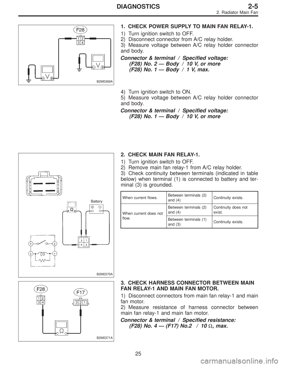
B2M0369A
1. CHECK POWER SUPPLY TO MAIN FAN RELAY-1.
1) Turn ignition switch to OFF.
2) Disconnect connector from A/C relay holder.
3) Measure voltage between A/C relay holder connector
and body.
Connector & terminal / Specified voltage:
(F28) No. 2—Body / 10 V, or more
(F28) No. 1—Body / 1 V, max.
4) Turn ignition switch to ON.
5) Measure voltage between A/C relay holder connector
and body.
Connector & terminal / Specified voltage:
(F28) No. 1—Body / 10 V, or more
B2M0370A
2. CHECK MAIN FAN RELAY-1.
1) Turn ignition switch to OFF.
2) Remove main fan relay-1 from A/C relay holder.
3) Check continuity between terminals (indicated in table
below) when terminal (1) is connected to battery and ter-
minal (3) is grounded.
When current flows.Between terminals (2)
and (4)Continuity exists.
When current does not
flow.Between terminals (2)
and (4)Continuity does not
exist.
Between terminals (1)
and (3)Continuity exists.
B2M0371A
3. CHECK HARNESS CONNECTOR BETWEEN MAIN
FAN RELAY-1 AND MAIN FAN MOTOR.
1) Disconnect connectors from main fan relay-1 and main
fan motor.
2) Measure resistance of harness connector between
main fan relay-1 and main fan motor.
Connector & terminal / Specified resistance:
(F28) No. 4—(F17) No.2 / 10Ω, max.
25
2-5DIAGNOSTICS
2. Radiator Main Fan
Page 466 of 3342
B2M0367A
4. CHECK GROUND CIRCUIT OF MAIN FAN MOTOR.
Measure resistance between main fan motor connector
and body.
Connector & terminal / Specified resistance:
(F17) No. 1—Body / 10Ω, max.
B2M0372A
5. CHECK MAIN FAN MOTOR.
1) Disconnect connector from main fan motor.
2) Connect battery positive (+) terminal to terminal No. 2
and connect terminal No. 1 to ground. Ensure that fan
rotates at LO speed.
26
2-5DIAGNOSTICS
2. Radiator Main Fan
Page 468 of 3342
![SUBARU LEGACY 1997 Service Repair Manual 1. CHECK OPERATION OF MAIN FAN MOTOR LO
MODE.
Check that radiator main fan rotates at LO speed under
each condition described under LO mode operation. <Ref.
to 2-5 [K2B0].>
B2M0374A
2. CHECK POWER SUP SUBARU LEGACY 1997 Service Repair Manual 1. CHECK OPERATION OF MAIN FAN MOTOR LO
MODE.
Check that radiator main fan rotates at LO speed under
each condition described under LO mode operation. <Ref.
to 2-5 [K2B0].>
B2M0374A
2. CHECK POWER SUP](/manual-img/17/57434/w960_57434-467.png)
1. CHECK OPERATION OF MAIN FAN MOTOR LO
MODE.
Check that radiator main fan rotates at LO speed under
each condition described under LO mode operation.
to 2-5 [K2B0].>
B2M0374A
2. CHECK POWER SUPPLY TO MAIN FAN RELAY-2.
1) Turn ignition switch to OFF.
2) Disconnect connector from A/C relay holder.
3) Measure voltage between A/C relay holder connector
and body.
Connector & terminal / Specified voltage:
(F30) No. 2—Body / 10 V, or more
(F30) No. 1—Body / 1 V, max.
4) Turn ignition switch to ON.
5) Measure voltage between A/C relay holder connector
and body.
Connector & terminal / Specified voltage:
(F30) No. 1—Body / 10 V, or more
B2M0370A
3. CHECK MAIN FAN RELAY-2.
1) Turn ignition switch to OFF.
2) Remove main fan relay-2 from A/C relay holder.
3) Check continuity between terminals (indicated in table
below) when terminal (1) is connected to battery and ter-
minal (3) is grounded.
When current flows.Between terminals (2)
and (4)Continuity exists.
When current does not
flow.Between terminals (2)
and (4)Continuity does not
exist.
Between terminals (1)
and (3)Continuity exists.
28
2-5DIAGNOSTICS
2. Radiator Main Fan
Page 469 of 3342
B2M0375A
4. CHECK HARNESS CONNECTOR BETWEEN MAIN
FAN RELAY-2 AND MAIN FAN MOTOR.
1) Disconnect connectors from main fan relay-2 and main
fan motor.
2) Measure resistance of harness connector between
main fan relay-2 and main fan motor.
Connector & terminal / Specified resistance:
(F30) No. 4—(F17) No. 3 / 10Ω, max.
B2M0367A
5. CHECK GROUND CIRCUIT OF MAIN FAN MOTOR.
Measure resistance between main fan motor connector
and body.
Connector & terminal / Specified resistance:
(F17) No. 1—Body / 10Ω, max.
B2M0368A
6. CHECK MAIN FAN MOTOR.
1) Disconnect connector from main fan motor.
2) Connect battery positive (+) terminal to terminals No. 2
and No. 3, and connect terminal No. 1 to ground. Ensure
that fan rotates at HI speed.
29
2-5DIAGNOSTICS
2. Radiator Main Fan
Page 507 of 3342
B2M0362
3) Remove pressure sources switching solenoid valve
from bracket.
4) Installation is in the reverse order of removal.
Tightening torque:
6.4±0.5 N⋅m (0.65±0.05 kg-m, 4.7±0.4 ft-lb)
G2M0398
14. Fuel Injector
A: REMOVAL AND INSTALLATION
1) Release fuel pressure.
2) Disconnect connector from fuel injector.
G2M0431
3) Remove fuel injector from fuel pipe assembly.
B2M0169A
4) Installation is in the reverse order of removal.
CAUTION:
Replace O-rings and insulator.
Tightening torque:
T: 3.4±0.5 N⋅m (0.35±0.05 kg-m, 2.5±0.4 ft-lb)
�
1O-ring B
�
2O-ring A
�
3Fuel injector
�
4Insulator
�
5Fuel injector cup
G6M0095
15. Engine Control Module
A: REMOVAL AND INSTALLATION
1) Disconnect battery ground cable.
31
2-7SERVICE PROCEDURE
13. Pressure Sources Switching Solenoid Valve (AT model) - 15. Engine Control Module