1997 SSANGYONG KORANDO sensor
[x] Cancel search: sensorPage 426 of 2053

1F2 -- 4 M161 ENGINE CONTROLS
D AEW OO M Y_2000
FASTENER TIGHTENING SPECIFICATIONS
ApplicationNSmLb-FtLb-In
Camshaft Position Sensor Retaining Bolts10--89
Canister Mounting Bolts6--53
Coolant Temperature Sensor3022--
Crankshaft Position Sensor Retaining Bolt10--89
Engine Control Module (ECM) Mounting Bracket Nuts10--89
Fuel Filter Mounting Bracket Bolt6--53
Fuel Filter Lines2821--
Fuel Pressure Test Connector2518--
Fuel Rail Assembly Bolts2518--
Fuel Return And Supply Lines2317--
Fuel Tank Retaining Nuts3828--
Knock Sensor Mounting Bolt2518--
Oxygen Sensor5541--
Pedal Position Censor Mounting Bolts And Nut6--53
Throttle Body Bolts12--106
Page 427 of 2053

M161 ENGINE CONTROLS 1F2 -- 5
D AEW OO M Y_2000
FUEL SYSTEM SPECIFICATION
Use Only Unleaded Fuel Rated at 89
Octane or Higher
Fuel quality and additives contained in fuel have a s ig n if i-
cant effect on power output, drivability, and life of the en-
gine.
Fuel with too low an octane number can cause engine
knock.
Caution: Use of fuel with an octane number lower
than 89 may damage engine and exhaust system.
Notice:To prevent accidental use of leaded fuel, the
nozzles for leaded fuel are larger, andwill not fit the fuel
filler neck of your vehicle.
Do Not Use Methanol
Fuels containing methanol (wood alcohol) should not be
used in vehicle.This type of fuel can reduce vehicle performance and
damage components of the fuel system.
Caution: Use of methanol may damage the fuel sys -
tem.
Vehicle Fueling from Drums or Storage
Containers
For safety reasons (particularly when using noncom-
mercial fueling systems) fuel containers, pumps and
hoses must be properly earthed.
Static electricity build up can occur under certain atmo-
spheric and fuel flow conditions if unearthed hoses, par-
ticularly plastic, are fitted to the fuel-- dispensing pump.
It is therefore recommended that earthed pumps with in-
tegrally earthed hoses be used, and that storage con-
tainers be properly earthed during all noncommercial
fueling operations.
TEMPERATURE VS RESISTANCE
°C°FECT sensorIAT sensor°C°FOHMS (Ω)
Temperature vs Resistance Values (Approximate)
13026688102
120248111. 6127
110230143159
100212202202
90194261261
80176340340
70158452452
60140609609
50122835835
40113116 61166
308616621662
206824202420
105036043604
03254995499
-- 1 01486098609
-- 2 0-- 41385013850
-- 3 0-- 2 22296022960
-- 4 0-- 4 03926039260
Page 436 of 2053

1F2 -- 14 M161 ENGINE CONTROLS
D AEW OO M Y_2000
DIAGNOSIS
FAILURE CODE DIAGNOSIS
CLEARING FAILURE CODES
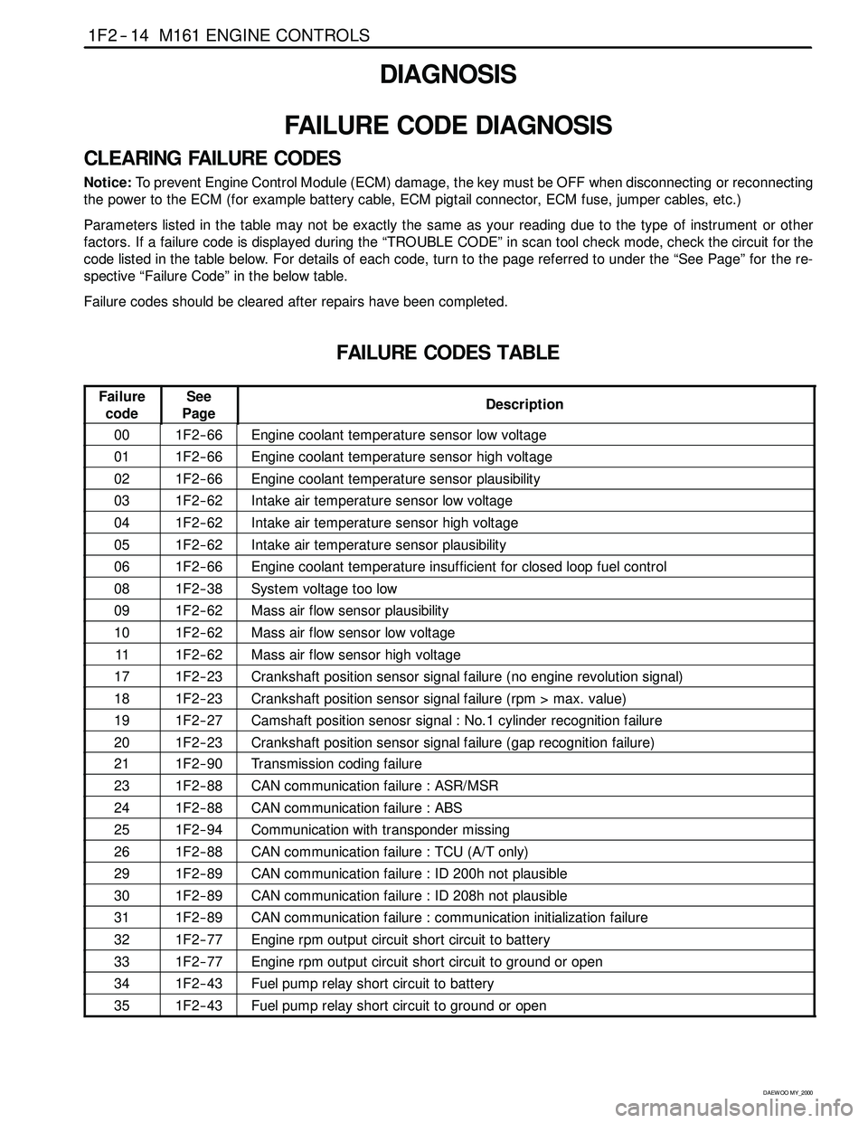
Notice:To prevent Engine Control Module (ECM) damage, the key must be OFF when disconnecting or reconnecting
the power to the ECM (for example battery cable, ECM pigtail connector, ECM fuse, jumper cables, etc.)
Parameters listed in the table may not be exactly the same as your reading due to the type of instrument or other
factors. If a failure code is displayed during the “TROUBLE CODE” in scan tool check mode, check the circuit for the
code listed in the table below. For details of each code, turn to the page referred to under the “See Page” for the re-
spective “Failure Code” in the below table.
Failure codes should be cleared after repairs have been completed.
FAILURE CODES TABLE
Failure
codeSee
PageDescription
001F2 -- 66Engine coolant temperature sensor low voltage
011F2 -- 66Engine coolant temperature sensor high voltage
021F2 -- 66Engine coolant temperature sensor plausibility
031F2 -- 62Intake air temperature sensor low voltage
041F2 -- 62Intake air temperature sensor high voltage
051F2 -- 62Intake air temperature sensor plausibility
061F2 -- 66Engine coolant temperature insufficient for closed loop fuel control
081F2 -- 38System voltage too low
091F2 -- 62Mass air flow sensor plausibility
101F2 -- 62Mass air flow sensor low voltage
111F2 -- 62Mass air flow sensor high voltage
171F2 -- 23Crankshaft position sensor signal failure (no engine revolution signal)
181F2 -- 23Crankshaft position sensor signal failure (rpm > max. value)
191F2 -- 27Camshaft position senosr signal : No.1 cylinder recognition failure
201F2 -- 23Crankshaft position sensor signal failure (gap recognition failure)
211F2 -- 90Transmission coding failure
231F2 -- 88CAN communication failure : ASR/MSR
241F2 -- 88CAN communication failure : ABS
251F2 -- 94Communication with transponder missing
261F2 -- 88CAN communication failure : TCU (A/T only)
291F2 -- 89CAN communication failure : ID 200h not plausible
301F2 -- 89CAN communication failure : ID 208h not plausible
311F2 -- 89CAN communication failure : communication initialization failure
321F2 -- 77Engine rpm output circuit short circuit to battery
331F2 -- 77Engine rpm output circuit short circuit to ground or open
341F2 -- 43Fuel pump relay short circuit to battery
351F2 -- 43Fuel pump relay short circuit to ground or open
Page 437 of 2053

M161 ENGINE CONTROLS 1F2 -- 15
D AEW OO M Y_2000
FAILURE CODES TABLE (Cont’d)
Failure
codeSee
PageDescription
401F2 -- 51Purge control valve short circuit to battery
411F2 -- 51Purge control valve short circuit to ground or open
441F2 -- 72Cooling fan (HI) relay short circuit to power
451F2 -- 72Cooling fan (HI) relay short circuit to ground or open
541F2 -- 51Purge control circuit malfunction
561F2 -- 33No.1 knock sensor signal failure
581F2 -- 27Camshaft position sensor signal : No.1 cylinder synchronization failure
591F2 -- 89CAN communication failure : MSR data transmission not plausible
601F2 -- 89CAN communication failure : ASR data transmission not plausible
641F2 -- 21No ignition voltage output (No.1 ignition coil)
651F2 -- 21No ignition voltage output (No.2 ignition coil)
671F2 -- 23Crankshaft position sensor adaptation failure
681F2 -- 35Random/Multiple Misfire
711F2 -- 39Starter signal recognition failure
721F2 -- 47No.1 injector short circuit to battery
731F2 -- 47No.1 injector short circuit to ground or open
741F2 -- 47No.2 injector short circuit to battery
751F2 -- 47No.2 injector short circuit to ground or open
761F2 -- 47No.3 injector short circuit to battery
771F2 -- 48No.3 injector short circuit to ground or open
781F2 -- 48No.4 injector short circuit to battery
791F2 -- 48No.4 injector short circuit to ground or open
801F2 -- 82Oxygen sensor high voltage
811F2 -- 83Bank 1 system short term fuel trim adaptation below lean threshold
821F2 -- 82Oxygen sensor no activity detected
831F2 -- 82Oxygen sensor not lean after overrun fuel shut -- off
841F2 -- 82Oxygen sensor slow response
851F2 -- 82Oxygen sensor heater failure
861F2 -- 82Oxygen sensor heater short circuit to battery
871F2 -- 82Oxygen sensor heater short circuit to ground or open
891F2 -- 82Oxygen sensor low voltage
931F2 -- 83Bank 1 system short term fuel trim adaptation above rich threshold
961F2 -- 83Bank 1 system short term fuel trim at rich stop
971F2 -- 83Bank 1 system short term fuel trim at lean stop
981F2 -- 83Bank 1 system idle adaptation failure (above rich threshold)
991F2 -- 83Bank 1 system idle adaptation failure (below lean threshold)
1001F2 -- 83Bank 1 system learning control failure (rich, low load)
1011F2 -- 83Bank 1 system learning control failure (lean, low load)
1021F2 -- 83Bank 1 system learning control failure (rich, high load)
Page 438 of 2053

1F2 -- 18 M161 ENGINE CONTROLS
D AEW OO M Y_2000
IGNITION SYSTEM
This ignition system does not use a conventional distributor andcoil. It uses a crankshaft position sensor input to the
Engine Control Module (ECM). The ECM then determines Electronic Spark Timing (EST) and triggers the electronic
ignition system ignition coil.
This type of distributorless ignition system uses a‘‘waste spark” method of spark distribution. Each cylinder is paired
with the cylinder that is opposite it (2 -- 3 or 1 -- 4). The spark occurs simultaneously in the cylinder coming up on the
compression stroke and in the cylinder coming up on the exhaust stroke. The cylinder on the exhaust stroke requires
very little of the available energy to fire the spark plug. The remaining energy is available to the spark plug in the cylin-
der on the compression stroke.
These systems use the EST signal from the ECM to control the EST. The ECM uses the following information:
DEngine load (mass air flow sensor).
DEngine temperature.
DIntake air temperature.
DCrankshaft position.
DEngine speed (rpm).
YAA1F910
Page 441 of 2053

M161 ENGINE CONTROLS 1F2 -- 21
D AEW OO M Y_2000
KAB1F420
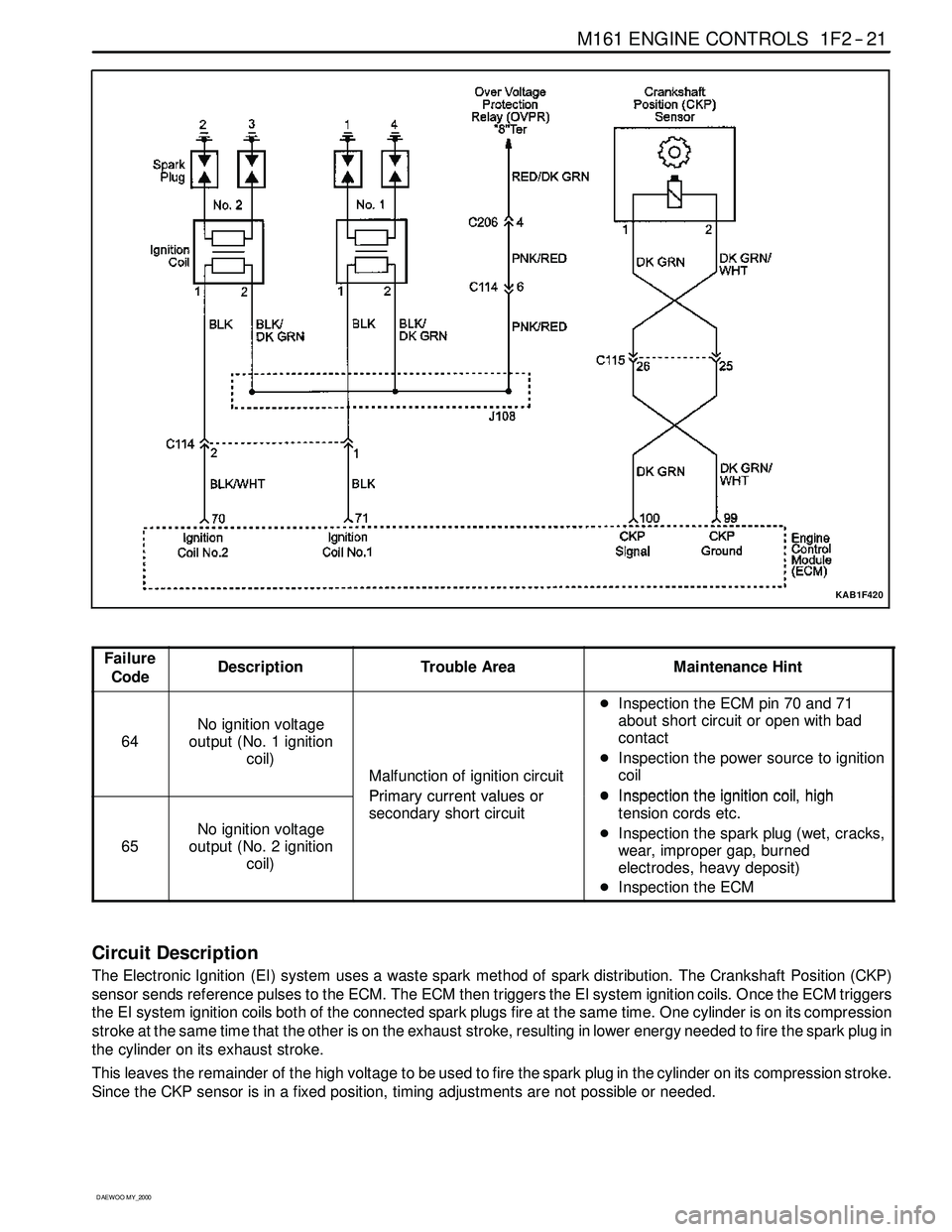
Failure
CodeDescriptionTrouble AreaMaintenance Hint
64
No ignition voltage
output (No. 1 ignition
coil)
Malfunction of ignition circuit
Primarycurrentvaluesor
DInspection the ECM pin 70 and 71
about short circuit or open with bad
contact
DInspection the power source to ignition
coil
DInspectiontheignitioncoilhigh
65
No ignition voltage
output (No. 2 ignition
coil)
Primary currentvalues or
secondary short circuitDInspectiontheignition coil,high
tension cords etc.
DInspection the spark plug (wet, cracks,
wear, improper gap, burned
electrodes, heavy deposit)
DInspection the ECM
Circuit Description
The Electronic Ignition (EI) system uses a waste spark method of spark distribution. The Crankshaft Position (CKP)
sensor sends reference pulses to the ECM. The ECM then triggers the EI system ignition coils. Once the ECM triggers
the EI system ignition coils both of the connected spark plugs fire at the same time. One cylinder is on its compression
stroke at the same time that the other is on the exhaust stroke, resulting in lower energy needed to fire the spark plug in
the cylinder on its exhaust stroke.
This leaves the remainder of the high voltage to be used to fire the spark plug in the cylinder on its compression stroke.
Since the CKP sensor is in a fixed position, timing adjustments are not possible or needed.
Page 442 of 2053

1F2 -- 22 M161 ENGINE CONTROLS
D AEW OO M Y_2000
CRANKSHAFT POSITION (CKP) SENSOR
YAA1F940
This Electronic Ignition (EI) system uses inductive or pickup type magnetic Crankshaft Position (CKP) sensor. The
CKP sensor is located in the opposite side of the crankshaft pulley and triggers the pick-up wheel teeth which is
equipped 60 -- 2 teeth with a gap of 2 teeth at 360 degree spacing. This sensor protrudes through its mount to within 1.1
±0.14 mm.
The output of the sensor is a sinusoidal signal. Each tooth of the pick-up 60 -- 2 wheel generates a positive half wave.
The Engine Control Module (ECM) uses this sensor signal to generate timed ignition and injection pulses that it sends
to the ignition coils and to the fuel injectors.
Page 443 of 2053

M161 ENGINE CONTROLS 1F2 -- 23
D AEW OO M Y_2000
KAB1F150
Failure
CodeDescriptionTrouble AreaMaintenance Hint
17
Crankshaft position
sensor signal failure (no
engine revolution signal)Even through cam position
recognition is normal, no
crankshaft position signal
recognition.
DMonitoring the actual rpm through or
scan tool
18
Crankshaft position
sensor signal failure
(rpm > max. value)When more than applicable
revolution values or
implausibleto60–2teeth.
scantool
DInspection the ECM pin 100, 99 about
short circuit with bad contact
DInspection the CKP sensor
20
Crankshaft position
sensor signal failure
(gap recognition failure)
When implausible recognition
of cam and crank angle signal
or intermittent sensing the
signal or error count of
undetected gap.
p
DInspection the air gap between sensor
and drive plate
DInspection the drive plate (teeth
condition)
DInspection the ECM
67Crankshaft position
sensor adaptation failureWhen faulty crank angle
sensor adaption.
p
Circuit Description
The 58X reference signal is produced by the CKP sensor. During one crankshaft revolution, 58 crankshaft pulseswill
be produced. The ECM uses the 58X reference signal to calculate engine rpm and CKP. The ECM constantly monitors
the number of pulses on the 58X reference circuit and compares them to the number of Camshaft Position (CMP)
signal pulses being received. If the ECM receives and incorrect number of pulses on the 58X reference circuit, this
failure code will set.
Crankshaft Position Sensor Resistance Inspection
1. Disconnect the coupling “E” of ECM while the ignition switch is in “OFF” position.
2. Measure the resistance between the coupling terminal pin No. 99 and No. 100 using a multimeter.
Specified Value
1,050 ~ 1,400Ω
Notice:Measure the insulator resistance of the CKP sensor if out of the specified value.