1997 SSANGYONG KORANDO trouble code connector
[x] Cancel search: trouble code connectorPage 1382 of 2053
SSANGYONG MY2002
5D1-12 TRANSFER CASE
Both Speed Sensor Faulty
If both the front and rear speed sensors are faulty con
tinuously for 0.5 seconds the 4WD CHECK lamp is
illuminated. The TCCU then responds as follows:
1. If the system is in high range the TCCU sets the
EMC touch off level based on a vehicle speed of
0 and wheel slip control is suspended.
2. If the system is in low range, the EMC duty cycle
is set to maximum until the system is shifted out
of low range.
3. All electric shift activity is halted until the Ignition
is cycled. If a shift is in progress it will be
completed.
If both speed sensors recover continuously for 0.5 sec-
ond the TCCU will function normally. The 4WD CHECK
lamp is turned off but the fault code will remain in
memory.
Electro-Magnetic Clutch Test
The electromagnetic clutch (EMC) is tested for open
circuit or short circuit to ground. If a fault is detected
continuously for 0.8 second the 4WD CHECK lamp is
turned on and all TODTM activity is halted.
If the EMC recovers continuously for 0.8 second the
TCCU will function normally. The 4WD CHECK lamp is
turned off but the fault code will remain in memory.
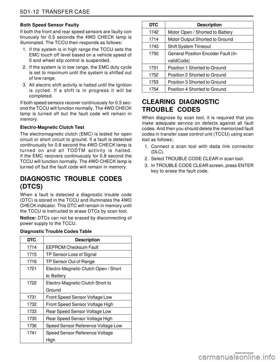
DIAGNOSTIC TROUBLE CODES
(DTCS)
When a fault is detected a diagnostic trouble code
(DTC) is stored in the TCCU and illuminates the 4WD
CHECK indicator. This DTC will remain in memory until
the TCCU is instructed to erase DTCs by scan tool.
Notice: DTCs can not be erased by disconnecting of
power supply to the TCCU.
Diagnostic Trouble Codes Table
CLEARING DIAGNOSTIC
TROUBLE CODES
When diagnose by scan tool, it is required that you
make adequate service on defects against all fault
codes. And then you should delete the memorized fault
codes in transfer case control unit (TCCU) using scan
tool as follows;
1. Connect a scan tool with dada link connector
(DLC).
2. Select TROUBLE CODE CLEAR in scan tool.
3. In TROUBLE CODE CLEAR screen, press ENTER
key to erase the fault code.
Description
EEPROM Checksum Fault
TP Sensor Loss of Signal
TP Sensor Out of Range
Electro-Magnetic Clutch Open / Short
to Battery
Electro-Magnetic Clutch Short to
Ground
Front Speed Sensor Voltage Low
Front Speed Sensor Voltage High
Rear Speed Sensor Voltage Low
Rear Speed Sensor Voltage High
Speed Sensor Reference Voltage Low
Speed Sensor Reference Voltage
High DTC
1714
1715
1716
1721
1722
1731
1732
1733
1735
1736
1741
Description
Motor Open / Shorted to Battery
Motor Output Shorted to Ground
Shift System Timeout
General Position Encoder Fault (In-
validCode)
Position 1 Shorted to Ground
Position 2 Shorted to Ground
Position 3 Shorted to Ground
Position 4 Shorted to Ground DTC
1742
1714
1743
1750
1751
1752
1753
1754
Page 1571 of 2053
FATC-HAVC 7D-17
SSANGYONG MY2002
KAA7D150
KAA7D160
KAA7D170
KAA7D180
TROUBLESHOOTING
Check and Service
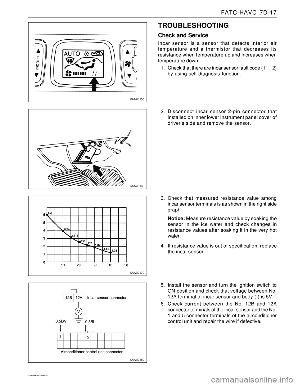
Incar sensor is a sensor that detects interior air
temperature and a thermistor that decreases its
resistance when temperature up and increases when
temperature down.
1. Check that there are incar sensor fault code (11,12)
by using self-diagnosis function.
2. Disconnect incar sensor 2-pin connector that
installed on inner lower instrument panel cover of
driver’s side and remove the sensor.
3. Check that measured resistance value among
incar sensor terminals is as shown in the right side
graph.
Notice: Measure resistance value by soaking the
sensor in the ice water and check changes in
resistance values after soaking it in the very hot
water.
4. If resistance value is out of specification, replace
the incar sensor.
5. Install the sensor and turn the ignition switch to
ON position and check that voltage between No.
12A terminal of incar sensor and body (-) is 5V.
6. Check current between the No. 12B and 12A
connector terminals of the incar sensor and the No.
1 and 5 connector terminals of the airconditioner
control unit and repair the wire if defective.
Page 1586 of 2053
SECTION 8B
SUPPLEMENTAL RESTRAINTS SYSTEM
CAUTION: Disconnect the negative battery cable before removing or installing any electrical unit or when a
tool or equipment could easily come in contact with exposed electrical terminals. Disconnecting this cable
will help prevent personal injury and damage to the vehicle. The ignition must also be in LOCK unless
other-wise noted.
TABLE OF CONTENTS
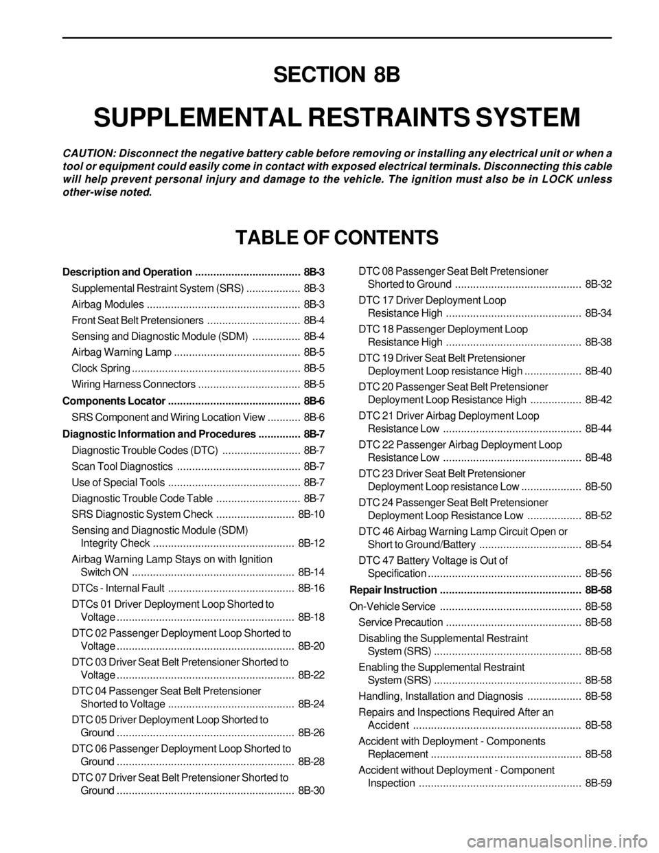
Description and Operation...................................8B-3
Supplemental Restraint System (SRS)..................8B-3
Airbag Modules...................................................8B-3
Front Seat Belt Pretensioners...............................8B-4
Sensing and Diagnostic Module (SDM)................8B-4
Airbag Warning Lamp ..........................................8B-5
Clock Spring........................................................8B-5
Wiring Harness Connectors..................................8B-5
Components Locator............................................8B-6
SRS Component and Wiring Location View...........8B-6
Diagnostic Information and Procedures..............8B-7
Diagnostic Trouble Codes (DTC)..........................8B-7
Scan Tool Diagnostics.........................................8B-7
Use of Special Tools............................................8B-7
Diagnostic Trouble Code Table............................8B-7
SRS Diagnostic System Check..........................8B-10
Sensing and Diagnostic Module (SDM)
Integrity Check...............................................8B-12
Airbag Warning Lamp Stays on with Ignition
Switch ON......................................................8B-14
DTCs - Internal Fault..........................................8B-16
DTCs 01 Driver Deployment Loop Shorted to
Voltage...........................................................8B-18
DTC 02 Passenger Deployment Loop Shorted to
Voltage...........................................................8B-20
DTC 03 Driver Seat Belt Pretensioner Shorted to
Voltage...........................................................8B-22
DTC 04 Passenger Seat Belt Pretensioner
Shorted to Voltage..........................................8B-24
DTC 05 Driver Deployment Loop Shorted to
Ground...........................................................8B-26
DTC 06 Passenger Deployment Loop Shorted to
Ground...........................................................8B-28
DTC 07 Driver Seat Belt Pretensioner Shorted to
Ground...........................................................8B-30DTC 08 Passenger Seat Belt Pretensioner
Shorted to Ground ..........................................8B-32
DTC 17 Driver Deployment Loop
Resistance High.............................................8B-34
DTC 18 Passenger Deployment Loop
Resistance High.............................................8B-38
DTC 19 Driver Seat Belt Pretensioner
Deployment Loop resistance High...................8B-40
DTC 20 Passenger Seat Belt Pretensioner
Deployment Loop Resistance High.................8B-42
DTC 21 Driver Airbag Deployment Loop
Resistance Low..............................................8B-44
DTC 22 Passenger Airbag Deployment Loop
Resistance Low..............................................8B-48
DTC 23 Driver Seat Belt Pretensioner
Deployment Loop resistance Low....................8B-50
DTC 24 Passenger Seat Belt Pretensioner
Deployment Loop Resistance Low..................8B-52
DTC 46 Airbag Warning Lamp Circuit Open or
Short to Ground/Battery..................................8B-54
DTC 47 Battery Voltage is Out of
Specification...................................................8B-56
Repair Instruction...............................................8B-58
On-Vehicle Service...............................................8B-58
Service Precaution.............................................8B-58
Disabling the Supplemental Restraint
System (SRS).................................................8B-58
Enabling the Supplemental Restraint
System (SRS).................................................8B-58
Handling, Installation and Diagnosis..................8B-58
Repairs and Inspections Required After an
Accident ........................................................8B-58
Accident with Deployment - Components
Replacement..................................................8B-58
Accident without Deployment - Component
Inspection......................................................8B-59
Page 1588 of 2053
SUPPLEMENTAL RESTRAINTS SYSTEM 8B-3
SSANGYONG MY2002
SUPPLEMENTAL RESTRAINT
SYSTEM (SRS)
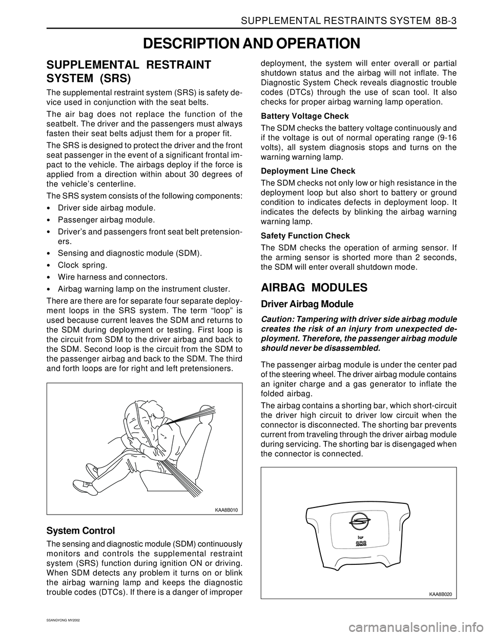
The supplemental restraint system (SRS) is safety de-
vice used in conjunction with the seat belts.
The air bag does not replace the function of the
seatbelt. The driver and the passengers must always
fasten their seat belts adjust them for a proper fit.
The SRS is designed to protect the driver and the front
seat passenger in the event of a significant frontal im-
pact to the vehicle. The airbags deploy if the force is
applied from a direction within about 30 degrees of
the vehicle’s centerline.
The SRS system consists of the following components:
Driver side airbag module.
Passenger airbag module.
Driver’s and passengers front seat belt pretension-
ers.
Sensing and diagnostic module (SDM).
Clock spring.
Wire harness and connectors.
Airbag warning lamp on the instrument cluster.
There are there are for separate four separate deploy-
ment loops in the SRS system. The term “loop” is
used because current leaves the SDM and returns to
the SDM during deployment or testing. First loop is
the circuit from SDM to the driver airbag and back to
the SDM. Second loop is the circuit from the SDM to
the passenger airbag and back to the SDM. The third
and forth loops are for right and left pretensioners.
DESCRIPTION AND OPERATION
KAA8B010
deployment, the system will enter overall or partial
shutdown status and the airbag will not inflate. The
Diagnostic System Check reveals diagnostic trouble
codes (DTCs) through the use of scan tool. It also
checks for proper airbag warning lamp operation.
Battery Voltage Check
The SDM checks the battery voltage continuously and
if the voltage is out of normal operating range (9-16
volts), all system diagnosis stops and turns on the
warning warning lamp.
Deployment Line Check
The SDM checks not only low or high resistance in the
deployment loop but also short to battery or ground
condition to indicates defects in deployment loop. It
indicates the defects by blinking the airbag warning
warning lamp.
Safety Function Check
The SDM checks the operation of arming sensor. If
the arming sensor is shorted more than 2 seconds,
the SDM will enter overall shutdown mode.
AIRBAG MODULES
Driver Airbag Module
Caution: Tampering with driver side airbag module
creates the risk of an injury from unexpected de-
ployment. Therefore, the passenger airbag module
should never be disassembled.
The passenger airbag module is under the center pad
of the steering wheel. The driver airbag module contains
an igniter charge and a gas generator to inflate the
folded airbag.
The airbag contains a shorting bar, which short-circuit
the driver high circuit to driver low circuit when the
connector is disconnected. The shorting bar prevents
current from traveling through the driver airbag module
during servicing. The shorting bar is disengaged when
the connector is connected.
System Control
The sensing and diagnostic module (SDM) continuously
monitors and controls the supplemental restraint
system (SRS) function during ignition ON or driving.
When SDM detects any problem it turns on or blink
the airbag warning lamp and keeps the diagnostic
trouble codes (DTCs). If there is a danger of improper
KAA8B020
Page 1589 of 2053
SSANGYONG MY2002
8B-4 SUPPLEMENTAL RESTRAINTS SYSTEM
KAA8B030
KAA8B040
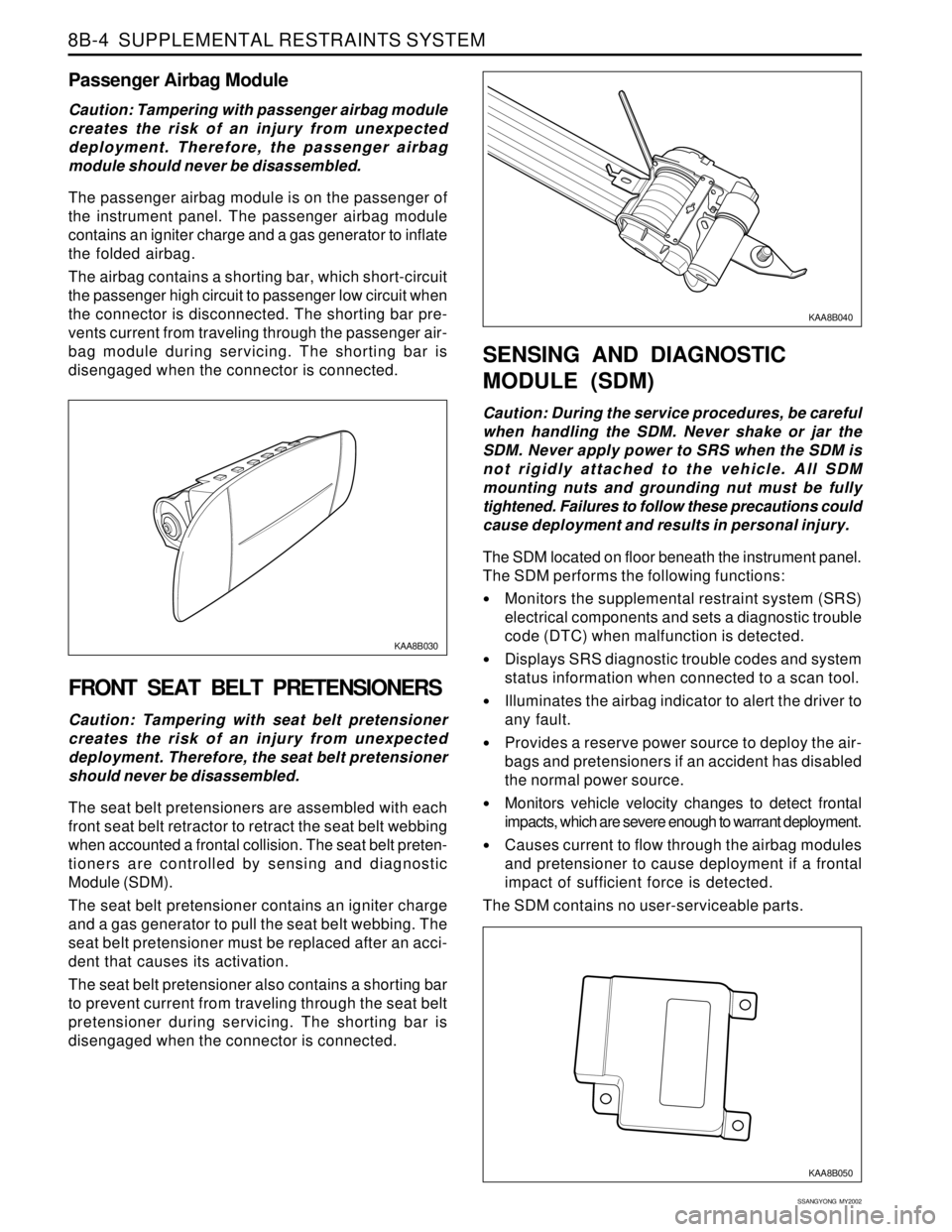
Passenger Airbag Module
Caution: Tampering with passenger airbag module
creates the risk of an injury from unexpected
deployment. Therefore, the passenger airbag
module should never be disassembled.
The passenger airbag module is on the passenger of
the instrument panel. The passenger airbag module
contains an igniter charge and a gas generator to inflate
the folded airbag.
The airbag contains a shorting bar, which short-circuit
the passenger high circuit to passenger low circuit when
the connector is disconnected. The shorting bar pre-
vents current from traveling through the passenger air-
bag module during servicing. The shorting bar is
disengaged when the connector is connected.
FRONT SEAT BELT PRETENSIONERS
Caution: Tampering with seat belt pretensioner
creates the risk of an injury from unexpected
deployment. Therefore, the seat belt pretensioner
should never be disassembled.
The seat belt pretensioners are assembled with each
front seat belt retractor to retract the seat belt webbing
when accounted a frontal collision. The seat belt preten-
tioners are controlled by sensing and diagnostic
Module (SDM).
The seat belt pretensioner contains an igniter charge
and a gas generator to pull the seat belt webbing. The
seat belt pretensioner must be replaced after an acci-
dent that causes its activation.
The seat belt pretensioner also contains a shorting bar
to prevent current from traveling through the seat belt
pretensioner during servicing. The shorting bar is
disengaged when the connector is connected.
SENSING AND DIAGNOSTIC
MODULE (SDM)
Caution: During the service procedures, be careful
when handling the SDM. Never shake or jar the
SDM. Never apply power to SRS when the SDM is
not rigidly attached to the vehicle. All SDM
mounting nuts and grounding nut must be fully
tightened. Failures to follow these precautions could
cause deployment and results in personal injury.
The SDM located on floor beneath the instrument panel.
The SDM performs the following functions:
Monitors the supplemental restraint system (SRS)
electrical components and sets a diagnostic trouble
code (DTC) when malfunction is detected.
Displays SRS diagnostic trouble codes and system
status information when connected to a scan tool.
Illuminates the airbag indicator to alert the driver to
any fault.
Provides a reserve power source to deploy the air-
bags and pretensioners if an accident has disabled
the normal power source.
Monitors vehicle velocity changes to detect frontal
impacts, which are severe enough to warrant deployment.
Causes current to flow through the airbag modules
and pretensioner to cause deployment if a frontal
impact of sufficient force is detected.
The SDM contains no user-serviceable parts.
KAA8B050
Page 1592 of 2053
SUPPLEMENTAL RESTRAINTS SYSTEM 8B-7
SSANGYONG MY2002
Driver Deployment Loop Shorted to Voltage
Passenger Deployment Loop Shorted to Voltage
Driver Seat Belt Pretensioner Shorted to Voltage
Passenger Seat Belt Pretensioner Shorted to Voltage
Driver Deployment Loop Shorted to Ground
Passenger Deployment Loop Shorted to Ground
Driver Seat Belt Pretensioner Shorted to Ground
Passenger Seat Belt Pretensioner Shorted to Ground
Driver Energy Shutdown Switch Error
Passenger Energy Shutdown Switch Error
Driver Seat Belt Pretensioner Energy Shutdown Switch Error
Passenger Seat Belt Pretensioner Energy Shutdown
Switch Error
Driver Ignition Switch Fault Internal
Passenger Ignition Switch Fault Internal
Driver Seat Belt Pretensioner Ignition Switch Fault
Passenger Seat Belt Pretensioner Ignition Switch Fault 01
02
03
04
05
06
07
08
09
10
11
12
13
14
15
16
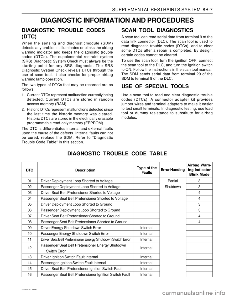
DIAGNOSTIC INFORMATION AND PROCEDURES
DIAGNOSTIC TROUBLE CODES
(DTC)
When the sensing and diagnosticmodule (SDM)
detects any problem it illuminates or blinks the airbag
warning indicator and keeps the diagnostic trouble
codes (DTCs). The supplemental restraint system
(SRS) Diagnostic System Check must always be the
starting point for any SRS diagnosis. The SRS
Diagnostic System Check reveals DTCs through the
use of scan tool. It also checks for proper airbag
warning lamp operation.
The two types of DTCs that may be recorded are as
follows:
1. Current DTCs represent malfunction currently being
detected. Current DTCs are stored in random
access memory (RAM).
2. Historic DTCs represent malfunctions detected since
the last time the historic memory was cleared.
Historic DTCs are stored in the electrically erasable
programmable read-only memory (EEPROM).
The DTC is differentiates internal and external faults
upon the cause of the defects. Internal faults can not
be cured, replace the SDM. Refer to “Diagnostic
Trouble Code Table” in this section.
SCAN TOOL DIAGNOSTICS
A scan tool can read serial data from terminal 9 of the
data link connector (DLC). The scan tool is used to
read diagnostic trouble codes (DTCs), and to clear
some DTCs after a repair is completed. By design,
certain codes cannot be cleared.
To use the scan tool, turn the ignition OFF, connect
the scan tool to the DLC, and turn the ignition switch
to ON. Follow the instructions in the scan tool manual.
The SDM sends serial data from terminal 20 of the
SDM to terminal 9 of the DLC.
USE OF SPECIAL TOOLS
Use a scan tool to read and clear diagnostic trouble
codes (DTCs). A connector adapter kit provides
jumper wires and terminal adapters to make it easier
to test small terminals. In diagnostic testing, use load
tool or dummy resistance to substitute for airbag
modules.
DIAGNOSTIC TROUBLE CODE TABLE
DTC DescriptionAirbag Warn-
ing Indicator
Blink Mode Error HandingType of the
Faults
Internal
Internal
Internal
Internal
Internal
Internal
Internal
Internal3
3
4
4
3
3
4
4
Partial
Shutdown
Page 1595 of 2053
SSANGYONG MY2002
8B-10 SUPPLEMENTAL RESTRAINTS SYSTEM
SRS DIAGNOSTIC SYSTEM CHECK
Notice: If the vehicle interior has been exposed to
extensive water intrusion such as water leaks, driving
through high water, flooding, or other caucuses, the
sensing and diagnostic module (SDM) and SDM
connector may be need to be replaced. With ignition
OFF, inspect the area around the SDM, including the
carpet. If any significant soaking or evidence of previous
soaking is detected, the water must be removed, water
damage repaired, and the SDM and SDM connector must
be replaced. Before attempting any of these repairs, the
supplemental restraint system (SRS) must be disabled.
Refer to “Disabling the SRS” and “Sensing and
Diagnostic Module (SDM)” in this section.
The SRS Diagnostic System Check must always be
the starting point for any SRS system diagnosis. The
SRS Diagnostic System Check reveals diagnostic
trouble codes (DTCs) through the use of scan tool.
The diagnostic procedures used in this section are
designed to find and repair SRS conditions. To get
the best results, it is important to use the diagnostic
charts and follow the sequence listed below.
1. Perform the SRS Diagnostic System Check, which
reveals diagnostic trouble codes (DTCs) through
the use of scan tool. It also checks for proper airbag
indicator operation.
2. Refer to the proper diagnostic chart as directed by
SRS Diagnostic System Check. Bypassing these
procedures may result in extended diagnostic time,
incorrect diagnosis, and incorrect parts
replacement.3. Repeat the SRS Diagnostic System Check after any
repair or diagnostic procedures have been
performed to ensure that the repair has beenmade
correctly and that no other malfunction exists.
Circuit Description
When the ignitions witch is first turned to ON, ignition
voltage is supplied from airbag fuse to the SDM at
input terminal 5. The SDM responds by turning on the
airbag indicator for 4.5 seconds and then turning it off
while the SDM performs tests on the SRS system.
Diagnostic Aids
The order in which DTCs are diagnosed is very
important. Failure to diagnose the DTCs in the order
specified may result in extended diagnostic time,
incorrect diagnosis, and incorrect parts replacement.
Test Description
The numbers below refer to steps on the diagnostic
table.
2. This test differentiates between an indicator that
will not come on and an indicator that stays on when
it should be off.
3. Refer to the first caution below
5. This test, along with step 6, differentiates internal
or external faults of SDM.
9. Refer to the cautions below.
Page 1618 of 2053
SSANGYONG MY2002
8B-34 SUPPLEMENTAL RESTRAINTS SYSTEM
Circuit Description
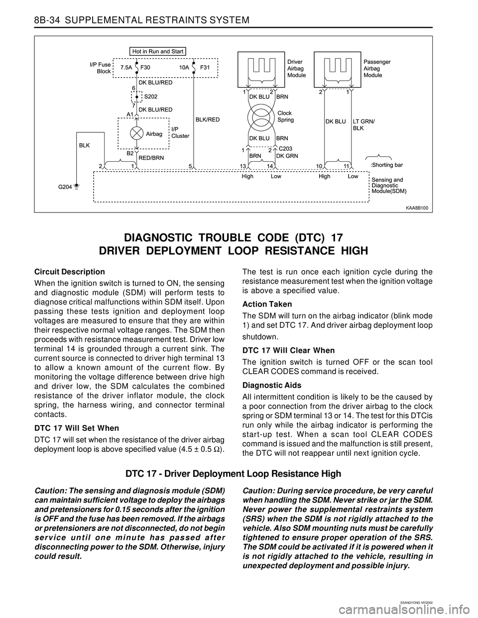
When the ignition switch is turned to ON, the sensing
and diagnostic module (SDM) will perform tests to
diagnose critical malfunctions within SDM itself. Upon
passing these tests ignition and deployment loop
voltages are measured to ensure that they are within
their respective normal voltage ranges. The SDM then
proceeds with resistance measurement test. Driver low
terminal 14 is grounded through a current sink. The
current source is connected to driver high terminal 13
to allow a known amount of the current flow. By
monitoring the voltage difference between drive high
and driver low, the SDM calculates the combined
resistance of the driver inflator module, the clock
spring, the harness wiring, and connector terminal
contacts.
DTC 17 Will Set When
DTC 17 will set when the resistance of the driver airbag
deployment loop is above specified value (4.5 ± 0.5 Ω).
DIAGNOSTIC TROUBLE CODE (DTC) 17
DRIVER DEPLOYMENT LOOP RESISTANCE HIGH
The test is run once each ignition cycle during the
resistance measurement test when the ignition voltage
is above a specified value.
Action Taken
The SDM will turn on the airbag indicator (blink mode
1) and set DTC 17. And driver airbag deployment loop
shutdown.
DTC 17 Will Clear When
The ignition switch is turned OFF or the scan tool
CLEAR CODES command is received.
Diagnostic Aids
All intermittent condition is likely to be the caused by
a poor connection from the driver airbag to the clock
spring or SDM terminal 13 or 14. The test for this DTCis
run only while the airbag indicator is performing the
start-up test. When a scan tool CLEAR CODES
command is issued and the malfunction is still present,
the DTC will not reappear until next ignition cycle.
KAA8B100
DTC 17 - Driver Deployment Loop Resistance High
Caution: The sensing and diagnosis module (SDM)
can maintain sufficient voltage to deploy the airbags
and pretensioners for 0.15 seconds after the ignition
is OFF and the fuse has been removed. If the airbags
or pretensioners are not disconnected, do not begin
service until one minute has passed after
disconnecting power to the SDM. Otherwise, injury
could result.Caution: During service procedure, be very careful
when handling the SDM. Never strike or jar the SDM.
Never power the supplemental restraints system
(SRS) when the SDM is not rigidly attached to the
vehicle. Also SDM mounting nuts must be carefully
tightened to ensure proper operation of the SRS.
The SDM could be activated if it is powered when it
is not rigidly attached to the vehicle, resulting in
unexpected deployment and possible injury.