Page 952 of 2053

SSANGYONG MY2002
4D-2 FRONT BRAKES
DESCRIPTION AND OPERATION
GENERAL DESCRIPTION
When the brakes are applied, fluid pressure is sent to
each brake caliper. The pressure at the caliper is ex-
erted equally against the caliper piston. The pressure
applied to the piston is transmitted directly to the
inboard brake pad. This forces the pad against the inner
surface of the brake rotor. At the same time, fluid
pressure within the caliper piston bore forces the caliper
to slide inward on its guide pins. This action brings the
outboard pad into contact with the outer surface of the
brake rotor. This pressure on both sides of the brake
rotor causes friction, bringing the vehicle to a stop.
BRAKE CALIPER
The caliper has a single bore and is mounted to the
steering knuckle with two mounting bolts. Hydraulic
pressure, created by applying the brake pedal, is con-
verted by the caliper to a stopping force. This force
acts equally against the piston and the bottom of the
caliper bore to move the piston outward and to slide
the caliper inward, resulting in a clamping action on
the rotor. This clamping action forces the linings against
the rotor, creating friction to stop the vehicle.Important:
•Replace all components included in the repair kits
used to service the caliper.
Lubricate the rubber parts with clean brake fluid to
ease assembly.
Do not use lubricated shop air on brake parts, as
damage to the rubber components may result.
If any hydraulic component is removed or discon-
nected, it may be necessary to bleed all or part of
the brake system. Refer to Section 4F, Antilock
Brake System And Traction Control System.
Replace the pads in axle sets only.
The torque values specified are for dry, unlubricated
fasteners.
Perform the service operations on a clean bench,
free from all oily material.
BRAKE PADS
There are two brake pads mounted to each caliper, one
inboard and one outboard. As front disc brake pad wear,
master cylinder reservoir brake fluid level will drop. Fluid
level should be checked after replacing pads.
BRAKE ROTOR
Each front disc brake rotor is vented to help cool it dur-
ing and after brake applications.
Page 1084 of 2053
ABS AND TCS 4F-101
SSANGYONG MY2002
FRONT WHEEL SPEED SENSOR
Removal and Installation Procedure
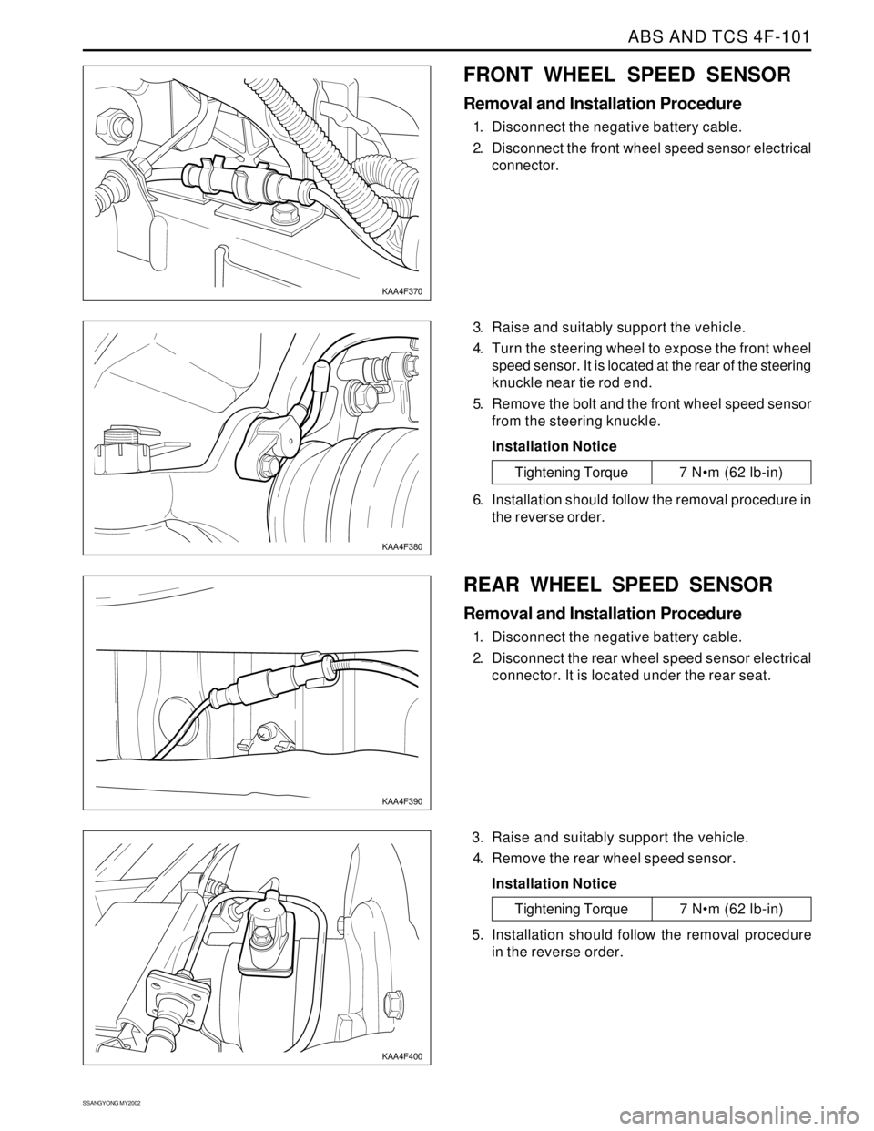
1. Disconnect the negative battery cable.
2. Disconnect the front wheel speed sensor electrical
connector.
3. Raise and suitably support the vehicle.
4. Turn the steering wheel to expose the front wheel
speed sensor. It is located at the rear of the steering
knuckle near tie rod end.
5. Remove the bolt and the front wheel speed sensor
from the steering knuckle.
Installation Notice
KAA4F370
KAA4F380
Tightening Torque 7 Nm (62 lb-in)
6. Installation should follow the removal procedure in
the reverse order.
REAR WHEEL SPEED SENSOR
Removal and Installation Procedure
1. Disconnect the negative battery cable.
2. Disconnect the rear wheel speed sensor electrical
connector. It is located under the rear seat.
3. Raise and suitably support the vehicle.
4. Remove the rear wheel speed sensor.
Installation Notice
KAA4F390
KAA4F400
Tightening Torque 7 Nm (62 lb-in)
5. Installation should follow the removal procedure
in the reverse order.
Page 1443 of 2053
SECTION 6A
POWER STEERING SYSTEM
TABLE OF CONTENTS
Description and Operation...................................6A-2
General Description.............................................6A-2
Component Locator.............................................6A-3
Diagnostic Information and Procedures..............6A-4
Power Steering System Pressure Test..................6A-4
Power Steering System Leak Test........................6A-4
Maintenance .........................................................6A-5
Bleeding the Power Steering System....................6A-5
Checking and Adding Fluid..................................6A-5Repair Instructions................................................6A-6
On-Vehicle Service.................................................6A-6
Power Steering Fluid Reservoir.............................6A-6
Power Steering Pump Hoses and Pipes................6A-7
Specifications.......................................................6A-9
General Specification...........................................6A-9
Fastener Tightening Specifications.......................6A-9
Special Tools and Equipment............................ 6A-10
Special Tools Table............................................6A-10
Page 1444 of 2053
SSANGYONG MY2002
6A-2 POWER STEERING SYSTEM
DESCRIPTION AND OPERATION
GENERAL DESCRIPTION
The power steering system consists of three compo
nents: the power steering pump, the power steering
fluid reservoir and the power steering rack and pinion
gear.
The power steering pump is a vane-type pump providing
hydraulic pressure for the system and is powered by
the engine. It draws on the power steering fluid
reservoir, which in turn is connected to the power
steering gear.A pressure-relief valve inside the flow control valve
limits the pump pressure. The power steering rack and
pinion gear has a rotary control valve, which directs
hydraulic fluid coming from the power steering pump
to one side or the other side of the rack piston. The
integral rack piston is attached to the rack. The rack
piston converts hydraulic pressure to a linear force,
which moves the rack to the left or the right. The force
is then transmitted through the inner and the outer tie
rods to the steering knuckles, which turn the wheels.
Page 1445 of 2053
POWER STEERING SYSTEM 6A-3
SSANGYONG MY2002
COMPONENT LOCATOR
KAA6A010
1 Steering Wheel
2 Steering Column Shaft
3 Tie Rod End4 Power Steering Gear Rack
5 Intermediate Shaft
6 Power Steering Pump
Page 1446 of 2053
SSANGYONG MY2002
6A-4 POWER STEERING SYSTEM
KAA6A020
DIAGNOSTIC INFORMATION AND PROCEDURES
POWER STEERING SYSTEM
PRESSURE TEST
Tools Required
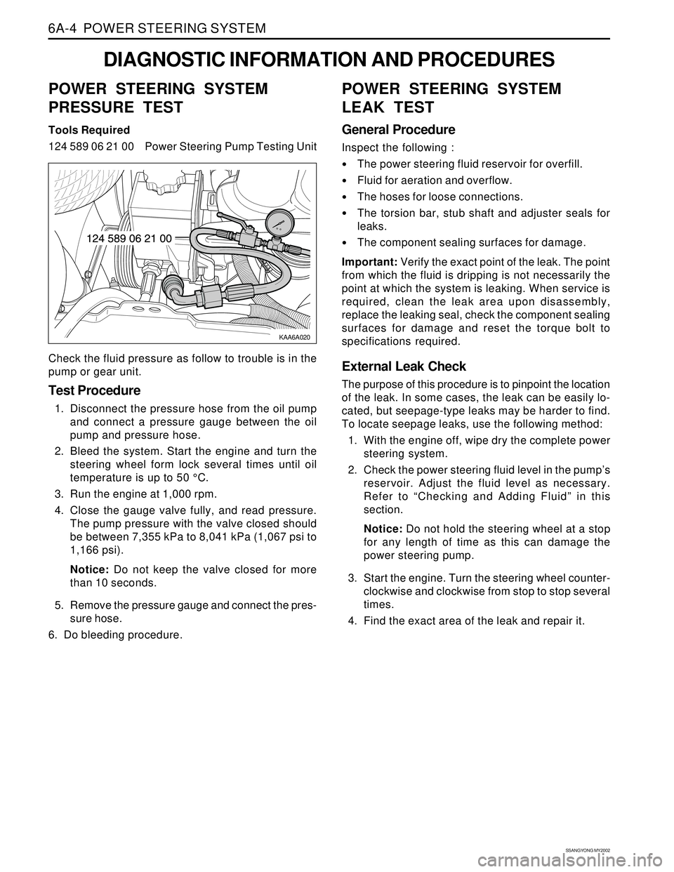
124 589 06 21 00 Power Steering Pump Testing Unit
Check the fluid pressure as follow to trouble is in the
pump or gear unit.
Test Procedure
1. Disconnect the pressure hose from the oil pump
and connect a pressure gauge between the oil
pump and pressure hose.
2. Bleed the system. Start the engine and turn the
steering wheel form lock several times until oil
temperature is up to 50 °C.
3. Run the engine at 1,000 rpm.
4. Close the gauge valve fully, and read pressure.
The pump pressure with the valve closed should
be between 7,355 kPa to 8,041 kPa (1,067 psi to
1,166 psi).
Notice: Do not keep the valve closed for more
than 10 seconds.
5. Remove the pressure gauge and connect the pres-
sure hose.
6. Do bleeding procedure.
POWER STEERING SYSTEM
LEAK TEST
General Procedure
Inspect the following :
The power steering fluid reservoir for overfill.
Fluid for aeration and overflow.
The hoses for loose connections.
The torsion bar, stub shaft and adjuster seals for
leaks.
The component sealing surfaces for damage.
Important: Verify the exact point of the leak. The point
from which the fluid is dripping is not necessarily the
point at which the system is leaking. When service is
required, clean the leak area upon disassembly,
replace the leaking seal, check the component sealing
surfaces for damage and reset the torque bolt to
specifications required.
External Leak Check
The purpose of this procedure is to pinpoint the location
of the leak. In some cases, the leak can be easily lo-
cated, but seepage-type leaks may be harder to find.
To locate seepage leaks, use the following method:
1. With the engine off, wipe dry the complete power
steering system.
2. Check the power steering fluid level in the pump’s
reservoir. Adjust the fluid level as necessary.
Refer to “Checking and Adding Fluid” in this
section.
Notice: Do not hold the steering wheel at a stop
for any length of time as this can damage the
power steering pump.
3. Start the engine. Turn the steering wheel counter-
clockwise and clockwise from stop to stop several
times.
4. Find the exact area of the leak and repair it.
Page 1447 of 2053

POWER STEERING SYSTEM 6A-5
SSANGYONG MY2002
BLEEDING THE POWER
STEERING SYSTEM
1. Disconnect the fuel line. Using a starter motor,
crank the engine and turn the steering wheel from
lock to start 5 or 6 times.
Notice: Do bleeding with engine cranking. If bleed
with idling, there can be a air contact with oil.
2. Connect the fuel feed line and start the engine at
idle speed.
3. Turn the steering wheel from lock to lock until there
is no more air in oil reservoir.
4. Connect the oil level is within specification.
5. By turning the steering wheel left to right, check
the oil level change.
Notice: If oil is not changes more than 5 mm, do
bleeding again. If oil level rises suddenly when
stopped engine, again.
MAINTENANCE
CHECKING AND ADDING FLUID
Notice: When adding fluid or making a complete fluid
change, always use DEXRON. - II power steering fluid.
Failure to use the proper fluid will cause hose and seal
damage and fluid leaks.
1. The power steering fluid level is indicated by marks
on a fluid level indicator on the fluid reservoir cap.
2. If the fluid is warmed up to 66 °C (150 °F), the fluid
level should be between the MAX and MIN marks.
Add fluid as needed.
3. If the fluid is cool, 21 °C (70 °F), the fluid level should
be at the MIN mark. Add fluid as needed.
Page 1448 of 2053
SSANGYONG MY2002
6A-6 POWER STEERING SYSTEM
KAA6A040
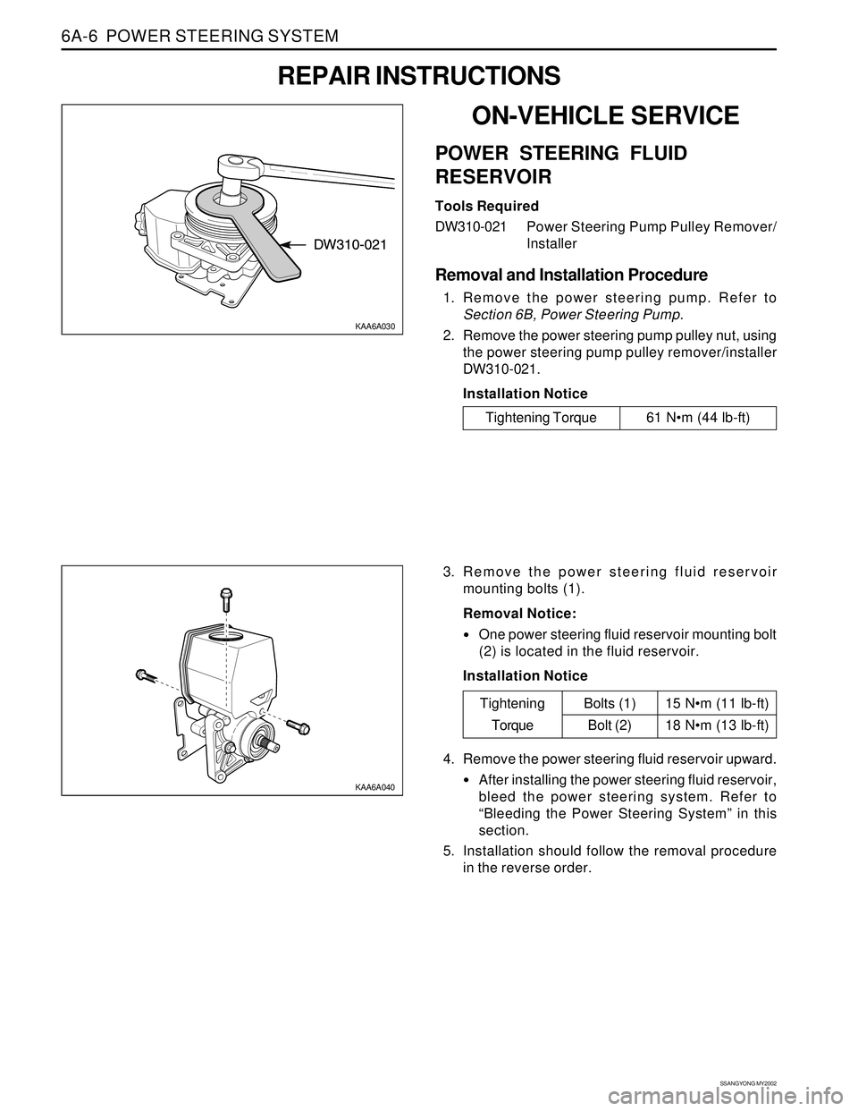
3. Remove the power steering fluid reservoir
mounting bolts (1).
Removal Notice:
One power steering fluid reservoir mounting bolt
(2) is located in the fluid reservoir.
Installation Notice
KAA6A030
ON-VEHICLE SERVICE
POWER STEERING FLUID
RESERVOIR
Tools Required
DW310-021Power Steering Pump Pulley Remover/
Installer
Removal and Installation Procedure
1. Remove the power steering pump. Refer to
Section 6B, Power Steering Pump.
2. Remove the power steering pump pulley nut, using
the power steering pump pulley remover/installer
DW310-021.
Installation Notice
REPAIR INSTRUCTIONS
Tightening Torque 61 Nm (44 lb-ft)
15 Nm (11 lb-ft)
18 Nm (13 lb-ft)
Tightening
TorqueBolts (1)
Bolt (2)
4. Remove the power steering fluid reservoir upward.
After installing the power steering fluid reservoir,
bleed the power steering system. Refer to
“Bleeding the Power Steering System” in this
section.
5. Installation should follow the removal procedure
in the reverse order.