Page 1475 of 2053
POWER STEERING GEAR 6C-7
SSANGYONG MY2002
Yes
Go to Step 2
Go to Step 3
Go to Step 5
Go to Step 2
Go to Step 3
System OK
Go to Step 6No
-
Go to Step 4
Go to Step 6
-
-
Go to Step 7
- Value
-
-
-
-
-
Inner angle :
33°39′
Outer angle :
31°54′
-Step
1
2
3
4
5
6
7Action
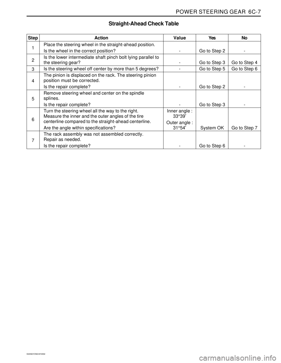
Place the steering wheel in the straight-ahead position.
Is the wheel in the correct position?
Is the lower intermediate shaft pinch bolt lying parallel to
the steering gear?
Is the steering wheel off center by more than 5 degrees?
The pinion is displaced on the rack. The steering pinion
position must be corrected.
Is the repair complete?
Remove steering wheel and center on the spindle
splines.
Is the repair complete?
Turn the steering wheel all the way to the right.
Measure the inner and the outer angles of the tire
centerline compared to the straight-ahead centerline.
Are the angle within specifications?
The rack assembly was not assembled correctly.
Repair as needed.
Is the repair complete?
Straight-Ahead Check Table
Page 1476 of 2053
SSANGYONG MY2002
6C-8 POWER STEERING GEAR
KAA6C040
KAA6C030
ON-VEHICLE SERVICE
RACK AND PINION ASSEMBLY
Tools Required
661 589 13 33 00 Ball Joint Remover
Removal and Installation Procedure
1. Raise and suitably support the vehicle.
2. Remove the wheels. Refer to Section 2E, Tires
and Wheels.
3. Remove the intermediate shaft. Refer to
“Intermediate shaft” in this section.
4. Disconnect the return line pipe from the power
steering gear outlet. Place a drain pan under the
steering gear to catch the power steering fluid.
Installation Notice
REPAIR INSTRUCTIONS
Tightening Torque 17 Nm (13 lb-ft)
5. Disconnect the pressure line pipe from the power
steering gear inlet.
Installation Notice
Tightening Torque 17 Nm (13 lb-ft)
Page 1477 of 2053
POWER STEERING GEAR 6C-9
SSANGYONG MY2002
KAA6C140
KAA6C050
KAA6C050
6. Remove the outer tie rod nuts and disconnect the
tie rod ends from the knuckle using the ball joint
remover 661 589 13 33 00.
Installation Notice
7. Remove the rack and pinion assembly mounting
bolts and remove therackand pinion assembly.
Installation Notice
Tightening Torque 40 Nm (30 lb-ft)
After installing the rack and pinion assembly,
bleed the power steering system. Refer to
Section 6A, Power Steering System.
OUTER TIE ROD
Tools Required
661589 13 33 00 BallJointRemover
Removal and Installation Procedure
1. Remove the wheel. Refer to Section 2E, Tires and
wheels.
2. Mark the threads on the inner tie rod to aid in
repositioning the adjusting nut.
3. Remove the outer tie rod nut and disconnect the
outer tie rod from the knuckle using the ball joint
remover 661 589 13 33 00.
Installation Notice
Tightening Torque 78 Nm (58 lb-ft)
Tightening Torque 40 Nm (30 lb-ft)
Page 1478 of 2053
SSANGYONG MY2002
6C-10 POWER STEERING GEAR
KAA6C090
KAA6C100
KAA6C110
KAA6C080
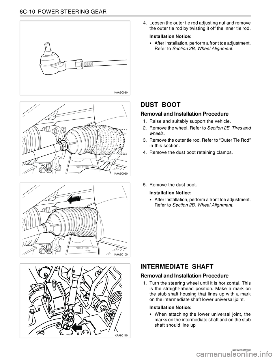
4. Loosen the outer tie rod adjusting nut and remove
the outer tie rod by twisting it off the inner tie rod.
Installation Notice:
After Installation, perform a front toe adjustment.
Refer to Section 2B, Wheel Alignment.
DUST BOOT
Removal and Installation Procedure
1. Raise and suitably support the vehicle.
2. Remove the wheel. Refer to Section 2E, Tires and
wheels.
3. Remove the outer tie rod. Refer to “Outer Tie Rod”
in this section.
4. Remove the dust boot retaining clamps.
5. Remove the dust boot.
Installation Notice:
After Installation, perform a front toe adjustment.
Refer to Section 2B, Wheel Alignment.
INTERMEDIATE SHAFT
Removal and Installation Procedure
1. Turn the steering wheel until it is horizontal. This
is the straight-ahead position. Make a mark on
the stub shaft housing that lines up with a mark
on the intermediate shaft lower universal joint.
Installation Notice:
When attaching the lower universal joint, the
marks on the intermediate shaft and on the stub
shaft should line up
Page 1481 of 2053
POWER STEERING GEAR 6C-13
SSANGYONG MY2002
KAA6C150
UNIT REPAIR
RACK AND PINION
Disassembly and Assembly Procedure
1. Remove the rack and pinion assembly from the
vehicle. Refer to “Rack and Pinion Assembly” in
this section.
2. Remove the valve and pinion assembly from the
rack and pinion steering assembly. Refer to “Valve
and Pinion” in this section.
3. Remove the rack bearing assembly from the rack
and pinion steering assembly. Refer to “Rack
Bearing” in this section.
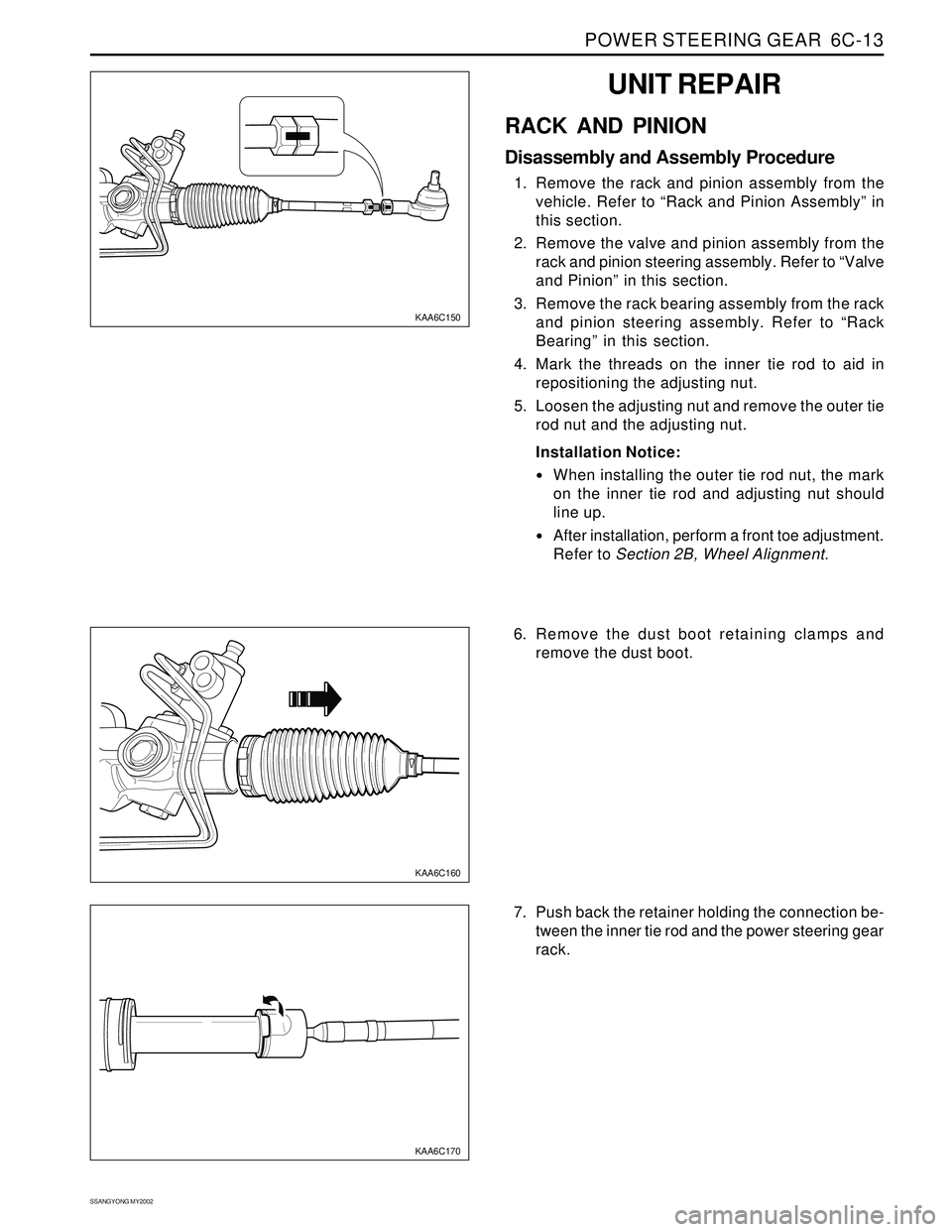
4. Mark the threads on the inner tie rod to aid in
repositioning the adjusting nut.
5. Loosen the adjusting nut and remove the outer tie
rod nut and the adjusting nut.
Installation Notice:
When installing the outer tie rod nut, the mark
on the inner tie rod and adjusting nut should
line up.
After installation, perform a front toe adjustment.
Refer to Section 2B, Wheel Alignment.
KAA6C160
KAA6C170
6. Remove the dust boot retaining clamps and
remove the dust boot.
7. Push back the retainer holding the connection be-
tween the inner tie rod and the power steering gear
rack.
Page 1484 of 2053
SSANGYONG MY2002
6C-16 POWER STEERING GEAR
KAA6C250
KAA6C260
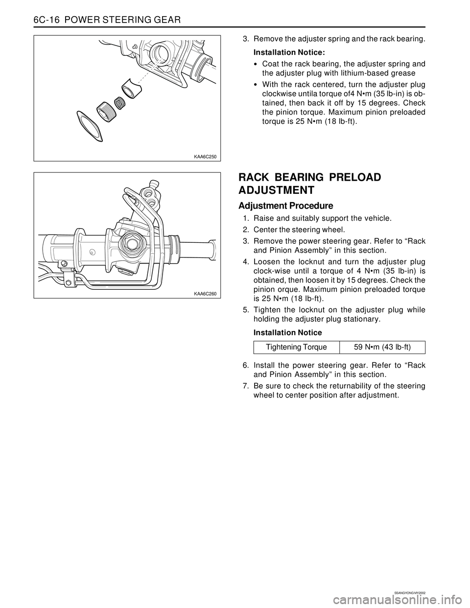
3. Remove the adjuster spring and the rack bearing.
Installation Notice:
Coat the rack bearing, the adjuster spring and
the adjuster plug with lithium-based grease
With the rack centered, turn the adjuster plug
clockwise untila torque of4 Nm (35 lb-in) is ob-
tained, then back it off by 15 degrees. Check
the pinion torque. Maximum pinion preloaded
torque is 25 Nm (18 lb-ft).
RACK BEARING PRELOAD
ADJUSTMENT
Adjustment Procedure
1. Raise and suitably support the vehicle.
2. Center the steering wheel.
3. Remove the power steering gear. Refer to “Rack
and Pinion Assembly” in this section.
4. Loosen the locknut and turn the adjuster plug
clock-wise until a torque of 4 Nm (35 lb-in) is
obtained, then loosen it by 15 degrees. Check the
pinion orque. Maximum pinion preloaded torque
is 25 Nm (18 lb-ft).
5. Tighten the locknut on the adjuster plug while
holding the adjuster plug stationary.
Installation Notice
Tightening Torque 59 Nm (43 lb-ft)
6. Install the power steering gear. Refer to “Rack
and Pinion Assembly” in this section.
7. Be sure to check the returnability of the steering
wheel to center position after adjustment.
Page 1487 of 2053
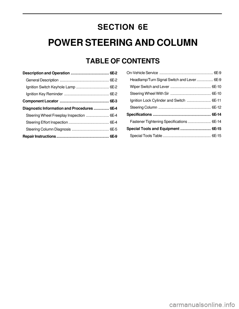
SECTION 6E
POWER STEERING AND COLUMN
TABLE OF CONTENTS
Description and Operation...................................6E-2
General Description.............................................6E-2
Ignition Switch Keyhole Lamp..............................6E-2
Ignition Key Reminder .........................................6E-2
Component Locator.............................................6E-3
Diagnostic Information and Procedures..............6E-4
Steering Wheel Freeplay Inspection.....................6E-4
Steering Effort Inspection.....................................6E-4
Steering Column Diagnosis..................................6E-5
Repair Instructions................................................6E-9On-Vehicle Service.................................................6E-9
Headlamp/Turn Signal Switch and Lever...............6E-9
Wiper Switch and Lever.....................................6E-10
Steering Wheel With Sir.....................................6E-10
Ignition Lock Cylinder and Switch......................6E-11
Steering Column................................................6E-12
Specifications.....................................................6E-14
Fastener Tightening Specifications.....................6E-14
Special Tools and Equipment............................6E-15
Special Tools Table............................................6E-15
Page 1488 of 2053
SSANGYONG MY2002
6E-2 POWER STEERING AND COLUMN
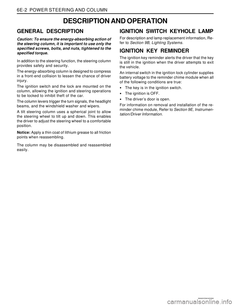
GENERAL DESCRIPTION
Caution: To ensure the energy-absorbing action of
the steering column, it is important to use only the
specified screws, bolts, and nuts, tightened to the
specified torque.
In addition to the steering function, the steering column
provides safety and security.
The energy-absorbing column is designed to compress
in a front-end collision to lessen the chance of driver
injury.
The ignition switch and the lock are mounted on the
column, allowing the ignition and steering operations
to be locked to inhibit theft of the car.
The column levers trigger the turn signals, the headlight
beams, and the windshield washer and wipers.
A tilt steering column uses a spherical joint to allow
the steering wheel to tilt up and down. This enables
the driver to adjust the steering wheel to a comfortable
position.
Notice: Apply a thin coat of lithium grease to all friction
points when reassembling.
The column may be disassembled and reassembled
easily.
DESCRIPTION AND OPERATION
IGNITION SWITCH KEYHOLE LAMP
For description and lamp replacement information, Re-
fer to Section 9B, Lighting Systems.
IGNITION KEY REMINDER
The ignition key reminder alerts the driver that the key
is still in the ignition when the driver attempts to exit
the vehicle.
An internal switch in the ignition lock cylinder supplies
battery voltage to the reminder chime module when all
of the following conditions are true:
•The key is in the ignition switch.
The ignition is OFF.
The driver’s door is open.
For information on removal and installation of the re-
minder chime module, Refer to Section 9E, Instrumen-
tation/Driver Information.