Page 864 of 2053
SSAMGYONG MY2002
3A-2 FRONT AXLE
M/T
A/T
M/T
A/T
M/T
A/T
M/T
A/T
SPECIFICATIONS
GENERAL SPECIFICATIONS
Application
Drive Shaft Type
Axle Housing Type
Differential Type
Differential GearCV Joint
Build - up
Conventional
Hypoid Gear
4.56
5.38
4.27
4.89
4.55
5.86
3.73
4.89
1.3 L
SEA 80W/90, API GL - 5Description
661LA
662LA
E23
E32 Reduction Ratio
Oil Capacity
Oil Specification
FASTENER TIGHTENING SPECIFICATIONS
Steering Knuckle and Drive Shaft
36.8 - 44.2
18.4 - 25.8
51.6 - 66.3
11.0
-
62.7 - 77.4 Drive Shaft Cover Bolt
Drive Shaft to Front Axle Inner Shaft
Hub Flange Bolt
Hub Nut
Locking Hub Washer Screw
Wheel Speed SensorN
�z �z�z �z
�zm ApplicationLb-InLb-Ft
50 - 60
25 - 35
70 - 90
15
2 - 4
85 - 105-
-
-
-
17.7 - 35.4
-
Page 870 of 2053
SSAMGYONG MY2002
3A-8 FRONT AXLE
Removal & Installation Procedure
1. Remove the tire.
Installation Notice
2. Remove the autolocking hub vacuum hose.
3. With ABS
Remove the wheel speed sensor from the steering
knuckle.
Installation Notice
4. Remove the mounting bolts and pull off the caliper
assembly.
Installation Notice
Notice: Be careful not to damage the brake hose.
KAA3A070
KAA3A080
KAA3A090
KAA3A100
Tightening
Torque80 - 120 Nm
(59 - 89 lb-ft)
110 - 130 Nm
(81 - 96 lb-ft)Steel Wheel
Aluminum
Wheel
Tightening Torque6 - 8 Nm
(53 - 71 lb-in)
Tightening
Torque25 - 35 Nm
(18 - 26 lb-ft)
85 - 105 Nm
(63 - 77 lb-ft)Hose Bolt
Mounting
Bolt
Page 1084 of 2053

ABS AND TCS 4F-101
SSANGYONG MY2002
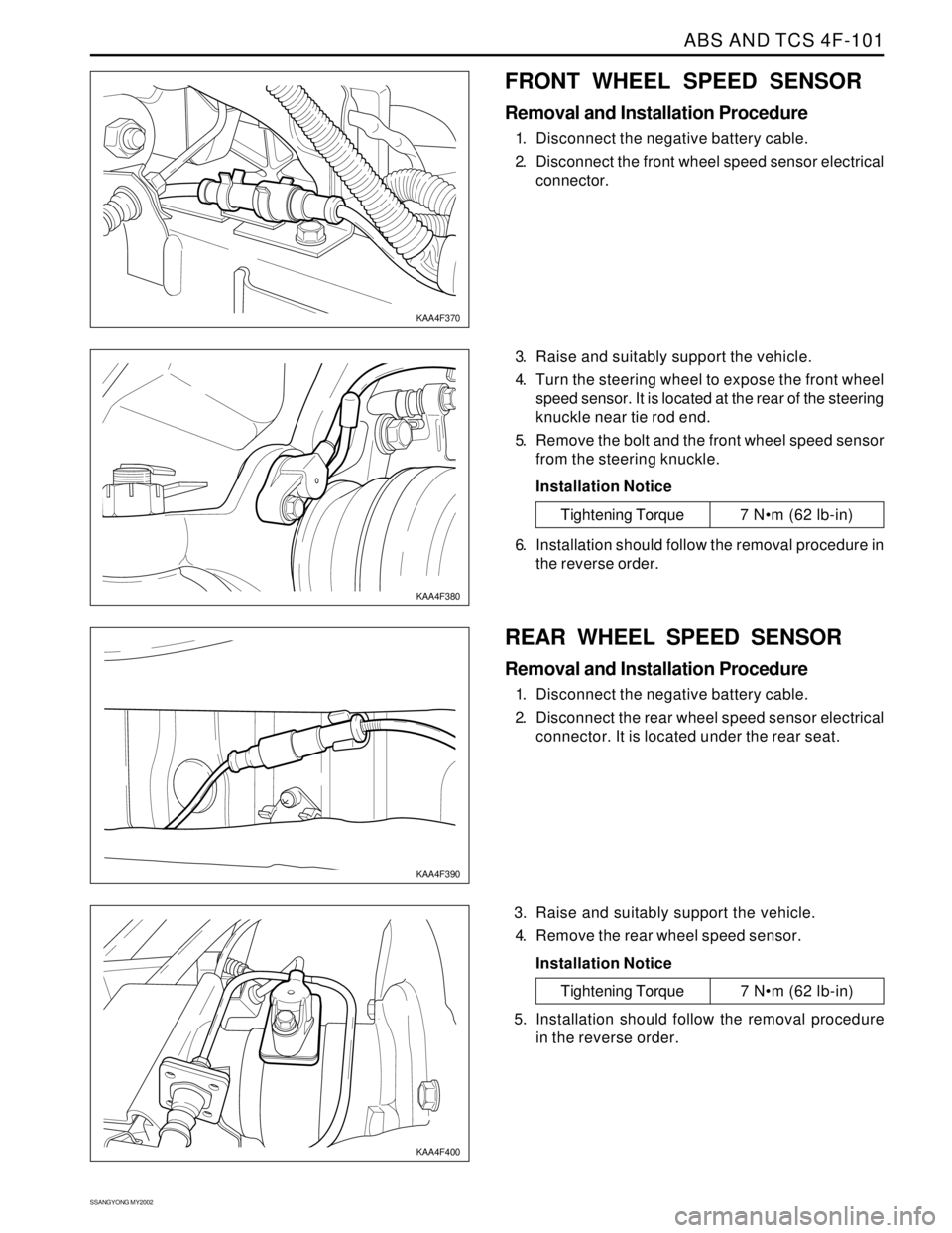
FRONT WHEEL SPEED SENSOR
Removal and Installation Procedure
1. Disconnect the negative battery cable.
2. Disconnect the front wheel speed sensor electrical
connector.
3. Raise and suitably support the vehicle.
4. Turn the steering wheel to expose the front wheel
speed sensor. It is located at the rear of the steering
knuckle near tie rod end.
5. Remove the bolt and the front wheel speed sensor
from the steering knuckle.
Installation Notice
KAA4F370
KAA4F380
Tightening Torque 7 Nm (62 lb-in)
6. Installation should follow the removal procedure in
the reverse order.
REAR WHEEL SPEED SENSOR
Removal and Installation Procedure
1. Disconnect the negative battery cable.
2. Disconnect the rear wheel speed sensor electrical
connector. It is located under the rear seat.
3. Raise and suitably support the vehicle.
4. Remove the rear wheel speed sensor.
Installation Notice
KAA4F390
KAA4F400
Tightening Torque 7 Nm (62 lb-in)
5. Installation should follow the removal procedure
in the reverse order.
Page 1444 of 2053

SSANGYONG MY2002
6A-2 POWER STEERING SYSTEM
DESCRIPTION AND OPERATION
GENERAL DESCRIPTION
The power steering system consists of three compo
nents: the power steering pump, the power steering
fluid reservoir and the power steering rack and pinion
gear.
The power steering pump is a vane-type pump providing
hydraulic pressure for the system and is powered by
the engine. It draws on the power steering fluid
reservoir, which in turn is connected to the power
steering gear.A pressure-relief valve inside the flow control valve
limits the pump pressure. The power steering rack and
pinion gear has a rotary control valve, which directs
hydraulic fluid coming from the power steering pump
to one side or the other side of the rack piston. The
integral rack piston is attached to the rack. The rack
piston converts hydraulic pressure to a linear force,
which moves the rack to the left or the right. The force
is then transmitted through the inner and the outer tie
rods to the steering knuckles, which turn the wheels.
Page 1445 of 2053
POWER STEERING SYSTEM 6A-3
SSANGYONG MY2002
COMPONENT LOCATOR
KAA6A010
1 Steering Wheel
2 Steering Column Shaft
3 Tie Rod End4 Power Steering Gear Rack
5 Intermediate Shaft
6 Power Steering Pump
Page 1446 of 2053

SSANGYONG MY2002
6A-4 POWER STEERING SYSTEM
KAA6A020
DIAGNOSTIC INFORMATION AND PROCEDURES
POWER STEERING SYSTEM
PRESSURE TEST
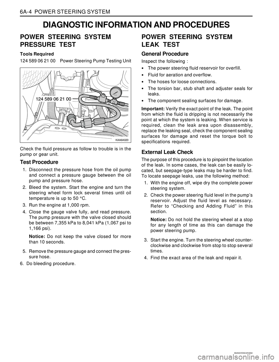
Tools Required
124 589 06 21 00 Power Steering Pump Testing Unit
Check the fluid pressure as follow to trouble is in the
pump or gear unit.
Test Procedure
1. Disconnect the pressure hose from the oil pump
and connect a pressure gauge between the oil
pump and pressure hose.
2. Bleed the system. Start the engine and turn the
steering wheel form lock several times until oil
temperature is up to 50 °C.
3. Run the engine at 1,000 rpm.
4. Close the gauge valve fully, and read pressure.
The pump pressure with the valve closed should
be between 7,355 kPa to 8,041 kPa (1,067 psi to
1,166 psi).
Notice: Do not keep the valve closed for more
than 10 seconds.
5. Remove the pressure gauge and connect the pres-
sure hose.
6. Do bleeding procedure.
POWER STEERING SYSTEM
LEAK TEST
General Procedure
Inspect the following :
The power steering fluid reservoir for overfill.
Fluid for aeration and overflow.
The hoses for loose connections.
The torsion bar, stub shaft and adjuster seals for
leaks.
The component sealing surfaces for damage.
Important: Verify the exact point of the leak. The point
from which the fluid is dripping is not necessarily the
point at which the system is leaking. When service is
required, clean the leak area upon disassembly,
replace the leaking seal, check the component sealing
surfaces for damage and reset the torque bolt to
specifications required.
External Leak Check
The purpose of this procedure is to pinpoint the location
of the leak. In some cases, the leak can be easily lo-
cated, but seepage-type leaks may be harder to find.
To locate seepage leaks, use the following method:
1. With the engine off, wipe dry the complete power
steering system.
2. Check the power steering fluid level in the pump’s
reservoir. Adjust the fluid level as necessary.
Refer to “Checking and Adding Fluid” in this
section.
Notice: Do not hold the steering wheel at a stop
for any length of time as this can damage the
power steering pump.
3. Start the engine. Turn the steering wheel counter-
clockwise and clockwise from stop to stop several
times.
4. Find the exact area of the leak and repair it.
Page 1447 of 2053

POWER STEERING SYSTEM 6A-5
SSANGYONG MY2002
BLEEDING THE POWER
STEERING SYSTEM
1. Disconnect the fuel line. Using a starter motor,
crank the engine and turn the steering wheel from
lock to start 5 or 6 times.
Notice: Do bleeding with engine cranking. If bleed
with idling, there can be a air contact with oil.
2. Connect the fuel feed line and start the engine at
idle speed.
3. Turn the steering wheel from lock to lock until there
is no more air in oil reservoir.
4. Connect the oil level is within specification.
5. By turning the steering wheel left to right, check
the oil level change.
Notice: If oil is not changes more than 5 mm, do
bleeding again. If oil level rises suddenly when
stopped engine, again.
MAINTENANCE
CHECKING AND ADDING FLUID
Notice: When adding fluid or making a complete fluid
change, always use DEXRON. - II power steering fluid.
Failure to use the proper fluid will cause hose and seal
damage and fluid leaks.
1. The power steering fluid level is indicated by marks
on a fluid level indicator on the fluid reservoir cap.
2. If the fluid is warmed up to 66 °C (150 °F), the fluid
level should be between the MAX and MIN marks.
Add fluid as needed.
3. If the fluid is cool, 21 °C (70 °F), the fluid level should
be at the MIN mark. Add fluid as needed.
Page 1453 of 2053

SSANGYONG MY2002
6A-2 POWER STEERING SYSTEM
DESCRIPTION AND OPERATION
GENERAL DESCRIPTION
The power steering system consists of three compo
nents: the power steering pump, the power steering
fluid reservoir and the power steering rack and pinion
gear.
The power steering pump is a vane-type pump providing
hydraulic pressure for the system and is powered by
the engine. It draws on the power steering fluid
reservoir, which in turn is connected to the power
steering gear.A pressure-relief valve inside the flow control valve
limits the pump pressure. The power steering rack and
pinion gear has a rotary control valve, which directs
hydraulic fluid coming from the power steering pump
to one side or the other side of the rack piston. The
integral rack piston is attached to the rack. The rack
piston converts hydraulic pressure to a linear force,
which moves the rack to the left or the right. The force
is then transmitted through the inner and the outer tie
rods to the steering knuckles, which turn the wheels.