1997 SSANGYONG KORANDO fuse
[x] Cancel search: fusePage 1170 of 2053
AUTOMATIC TRANSMISSION 5A-75
SSANGYONG MY2002
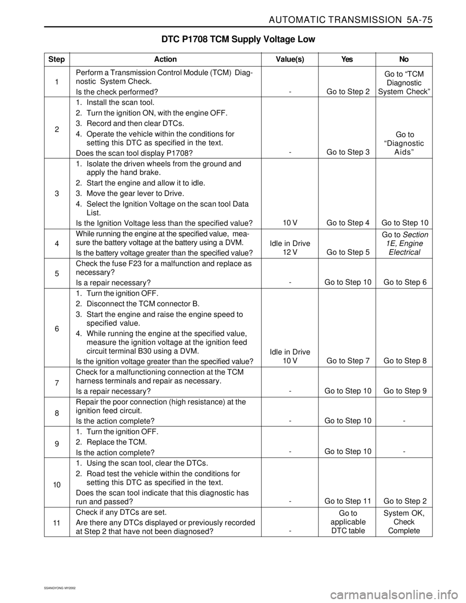
DTC P1708 TCM Supply Voltage Low
1Perform a Transmission Control Module (TCM) Diag-
nostic System Check.
Is the check performed?
1. Install the scan tool.
2. Turn the ignition ON, with the engine OFF.
3. Record and then clear DTCs.
4. Operate the vehicle within the conditions for
setting this DTC as specified in the text.
Does the scan tool display P1708?
1. Isolate the driven wheels from the ground and
apply the hand brake.
2. Start the engine and allow it to idle.
3. Move the gear lever to Drive.
4. Select the Ignition Voltage on the scan tool Data
List.
Is the Ignition Voltage less than the specified value?
While running the engine at the specified value, mea-
sure the battery voltage at the battery using a DVM.
Is the battery voltage greater than the specified value?
Check the fuse F23 for a malfunction and replace as
necessary?
Is a repair necessary?
1. Turn the ignition OFF.
2. Disconnect the TCM connector B.
3. Start the engine and raise the engine speed to
specified value.
4. While running the engine at the specified value,
measure the ignition voltage at the ignition feed
circuit terminal B30 using a DVM.
Is the ignition voltage greater than the specified value?
Check for a malfunctioning connection at the TCM
harness terminals and repair as necessary.
Is a repair necessary?
Repair the poor connection (high resistance) at the
ignition feed circuit.
Is the action complete?
1. Turn the ignition OFF.
2. Replace the TCM.
Is the action complete?
1. Using the scan tool, clear the DTCs.
2. Road test the vehicle within the conditions for
setting this DTC as specified in the text.
Does the scan tool indicate that this diagnostic has
run and passed?
Check if any DTCs are set.
Are there any DTCs displayed or previously recorded
at Step 2 that have not been diagnosed?
StepAction Value(s) Yes No
2
3
5
- Go to Step 10 Go to Step 9 6 4
- Go to Step 10 - 7
- Go to Step 10 - 8
- Go to Step 11 Go to Step 2 9
10
- Go to Step 2Go to “TCM
Diagnostic
System Check”
10 V Go to Step 4 Go to Step 10
- Go to Step 3 Go to
“Diagnostic
Aids”
11
-Go to
applicable
DTC tableSystem OK,
Check
Complete
- Go to Step 10 Go to Step 6
Idle in Drive
10 V Go to Step 7 Go to Step 8
Idle in Drive
12 V Go to Step 5 Go to Section
1E, Engine
Electrical
Page 1172 of 2053
AUTOMATIC TRANSMISSION 5A-77
SSANGYONG MY2002
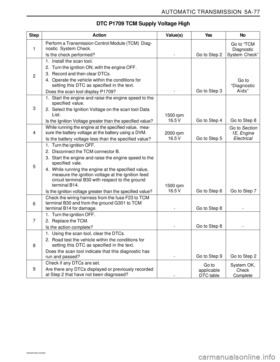
DTC P1709 TCM Supply Voltage High
1Perform a Transmission Control Module (TCM) Diag-
nostic System Check.
Is the check performed?
1. Install the scan tool.
2. Turn the ignition ON, with the engine OFF.
3. Record and then clear DTCs.
4. Operate the vehicle within the conditions for
setting this DTC as specified in the text.
Does the scan tool display P1709?
1. Start the engine and raise the engine speed to the
specified value.
2. Select the Ignition Voltage on the scan tool Data
List.
Is the Ignition Voltage greater than the specified value?
While running the engine at the specified value, mea-
sure the battery voltage at the battery using a DVM.
Is the battery voltage less than the specified value?
1. Turn the ignition OFF.
2. Disconnect the TCM connector B.
3. Start the engine and raise the engine speed to the
specified vale.
4. While running the engine at the specified value,
measure the ignition voltage at the ignition feed
circuit terminal B30 with respect to the ground
terminal B14.
Is the ignition voltage greater than the specified value?
Check the wiring harness from the fuse F23 to TCM
terminal B30 and from the ground G301 to TCM
terminal B14 for damage.
1. Turn the ignition OFF.
2. Replace the TCM.
Is the action complete?
1. Using the scan tool, clear the DTCs.
2. Road test the vehicle within the conditions for
setting this DTC as specified in the text.
Does the scan tool indicate that this diagnostic has
run and passed?
Check if any DTCs are set.
Are there any DTCs displayed or previously recorded
at Step 2 that have not been diagnosed?
StepAction Value(s) Yes No
2
3
5
6 4
- Go to Step 8 -
7
- Go to Step 8 -
8
- Go to Step 9 Go to Step 2
9
- Go to Step 2Go to “TCM
Diagnostic
System Check”
- Go to Step 3 Go to
“Diagnostic
Aids”
1500 rpm
16.5 V
Go to Step 6 Go to Step 7
1500 rpm
16.5 V Go to Step 4 Go to Step 8
2000 rpm
16.5 V Go to Step 5 Go to Section
1E, Engine
Electrical
-Go to
applicable
DTC tableSystem OK,
Check
Complete
Page 1174 of 2053
AUTOMATIC TRANSMISSION 5A-79
SSANGYONG MY2002
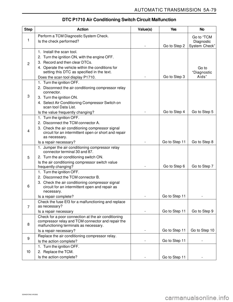
DTC P1710 Air Conditioning Switch Circuit Malfunction
1Perform a TCM Diagnostic System Check.
Is the check performed?
1. Install the scan tool.
2. Turn the ignition ON, with the engine OFF.
3. Record and then clear DTCs.
4. Operate the vehicle within the conditions for
setting this DTC as specified in the text.
Does the scan tool display P1710.
1. Turn the ignition OFF.
2. Disconnect the air conditioning compressor relay
connector.
3. Turn the ignition ON.
4. Select Air Conditioning Compressor Switch on
scan tool Data List.
Is the value frequently changing?
1. Turn the ignition OFF.
2. Disconnect the TCM connector A.
3. Check the air conditioning compressor signal
circuit for an intermittent open or short and repair
as necessary.
Is a repair necessary?
1. Jumper the air conditioning compressor relay
connector terminal 30 and 87.
2. Turn the air conditioning switch ON.
Is the air conditioning compressor switch value
frequently changing?
1. Turn the ignition OFF.
2. Disconnect the TCM connector B.
3. Check the air conditioning compressor signal
circuit for an intermittent open and repair as
necessary.
Is a repair complete?
Check the fuse Ef3 for a malfunctioning and replace
as necessary?
Is a repair necessary
Check for a poor connection at the air conditioning
compressor relay and TCM connector and repair the
malfunctioning terminals as necessary.
Is a repair necessary?
Replace the air conditioning compressor relay.
Is the action complete?
1. Turn the ignition OFF.
2. Replace the TCM.
Is the action complete?
StepAction Value(s) Yes No
2
3
4
5
- Go to Step 2Go to “TCM
Diagnostic
System Check”
6
7
8
9
10
- Go to Step 3 Go to
“Diagnostic
Aids”
- Go to Step 4 Go to Step 5
- Go to Step 11 Go to Step 8
- Go to Step 6 Go to Step 7
- Go to Step 11 -
- Go to Step 11 Go to Step 9
- Go to Step 11 Go to Step 10
- Go to Step 11 -
- Go to Step 11 -
Page 1373 of 2053
TRANSFER CASE 5D1-3
SSANGYONG MY2002
A1
A2
A3
A4
A5
A6
A7
A8
A9
A10
A11
A12
B1
B2
B3
B4
B5
B6
B7
B8
B9
B10
B11
B12
B13
B14
B15
B16
B17
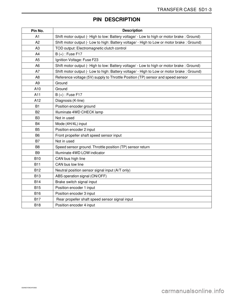
B18Shift motor output (- High to low: Battery voltage/ - Low to high or motor brake : Ground)
Shift motor output (- Low to high: Battery voltage/ - High to Low or motor brake : Ground)
TOD output: Electromagnetic clutch control
B (+) : Fuse F17
Ignition Voltage: Fuse F23
Shift motor output (- High to low: Battery voltage/ - Low to high or motor brake : Ground)
Shift motor output (- Low to high: Battery voltage/ - High to Low or motor brake : Ground)
Reference voltage (5V) supply to Throttle Position (TP) sensor and speed sensor
Ground
Ground
B (+) : Fuse F17
Diagnosis (K-line)
Position encoder ground
Illuminate 4WD CHECK lamp
Not in used
Mode (4H/4L) input
Position encoder 2 input
Front propeller shaft speed sensor input
Not in used
Speed sensor ground. Throttle position (TP) sensor return
Illuminate 4WD LOW indicator
CAN bus high line
CAN bus low line
Neutral position sensor signal input (A/T only)
ABS operation signal (ON/OFF)
Brake switch signal input
Position encoder 1 input
Position encoder 3 input
Rear propeller shaft speed sensor signal input
Position encoder 4 input
PIN DESCRIPTION
Pin No.Description
Page 1509 of 2053
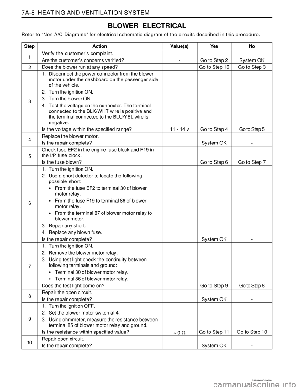
SSANGYONG MY2002
7A-8 HEATING AND VENTILATION SYSTEM
BLOWER ELECTRICAL
Refer to “Non A/C Diagrams” for electrical schematic diagram of the circuits described in this procedure.
Step
1
2
3
4
5
6
7
8
9
10
Action
Verify the customer’s complaint.
Are the customer’s concerns verified?
Does the blower run at any speed?
1. Disconnect the power connector from the blower
motor under the dashboard on the passenger side
of the vehicle.
2. Turn the ignition ON.
3. Turn the blower ON.
4. Test the voltage on the connector. The terminal
connected to the BLK/WHT wire is positive and
the terminal connected to the BLU/YEL wire is
negative.
Is the voltage within the specified range?
Replace the blower motor.
Is the repair complete?
Check fuse EF2 in the engine fuse block and F19 in
the I/P fuse block.
Is the fuse blown?
1. Turn the ignition ON.
2. Use a short detector to locate the following
possible short:
From the fuse EF2 to terminal 30 of blower
motor relay.
From the fuse F19 to terminal 86 of blower
motor relay.
From the terminal 87 of blower motor relay to
blower motor.
3. Repair any short.
4. Replace any blown fuse.
Is the repair complete?
1. Turn the ignition ON.
2. Remove the blower motor relay.
3. Using test light check the continuity between
following terminals and ground:
Terminal 30 of blower motor relay.
Terminal 86 of blower motor relay.
Does the test light come on?
Repair the open circuit.
Is the repair complete?
1. Turn the ignition OFF.
2. Set the blower motor switch at 4.
3. Using ohmmeter, measure the resistance between
terminal 85 of blower motor relay and ground.
Is the resistance within specified value?
Repair open circuit.
Is the repair complete?Yes
Go to Step 2
Go to Step 16
Go to Step 4
System OK
Go to Step 6
System OK
Go to Step 9
System OK
Go to Step 11
System OKNo
System OK
Go to Step 3
Go to Step 5
-
Go to Step 7
-
Go to Step 8
-
Go to Step 10
-
Value(s)
-
11 - 14 v
≈ 0 Ω
Page 1511 of 2053
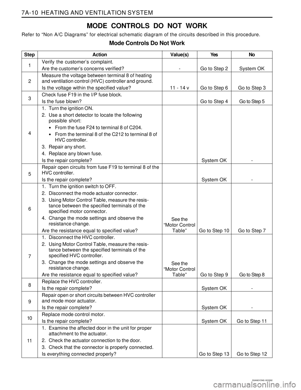
SSANGYONG MY2002
7A-10 HEATING AND VENTILATION SYSTEM
MODE CONTROLS DO NOT WORK
Refer to “Non A/C Diagrams” for electrical schematic diagram of the circuits described in this procedure.
Mode Controls Do Not Work
Step
1
2
3
4
5
6
7
8
9
10
11Action
Verify the customer’s complaint.
Are the customer’s concerns verified?
Measure the voltage between terminal 8 of heating
and ventilation control (HVC) controller and ground.
Is the voltage within the specified value?
Check fuse F19 in the I/P fuse block.
Is the fuse blown?
1. Turn the ignition ON.
2. Use a short detector to locate the following
possible short:
From the fuse F24 to terminal 8 of C204.
From the terminal 8 of the C212 to terminal 8 of
HVC controller.
3. Repair any short.
4. Replace any blown fuse.
Is the repair complete?
Repair open circuits from fuse F19 to terminal 8 of the
HVC controller.
Is the repair complete?
1. Turn the ignition switch to OFF.
2. Disconnect the mode actuator connector.
3. Using Motor Control Table, measure the resis-
tance between the specified terminals of the
specified motor connector.
4. Change the mode settings and observe the
resistance change.
Are the resistance equal to specified value?
1. Disconnect the HVC controller.
2. Using Motor Control Table, measure the resis-
tance between the specified terminals of the
specified HVC controller.
3. Change the mode settings and observe the
resistance change.
Are the resistance equal to specified value?
Replace the HVC controller.
Is the repair complete?
Repair open or short circuits between HVC controller
and mode moor actuator.
Is the repair complete?
Replace mode control motor.
Is the repair complete?
1. Examine the affected door in the unit for proper
attachment to the actuator.
2. Check the actuator connection to the door.
3. Check that the connector is properly connected.
Is everything connected properly?Yes
Go to Step 2
Go to Step 6
Go to Step 4
System OK
System OK
Go to Step 10
Go to Step 9
System OK
System OK
System OK
Go to Step 13No
System OK
Go to Step 3
Go to Step 5
-
-
Go to Step 7
Go to Step 8
-
-
Go to Step 11
Go to Step 12
Value(s)
-
11 - 14 v
See the
“Motor Control
Table”
See the
“Motor Control
Table”
Page 1513 of 2053
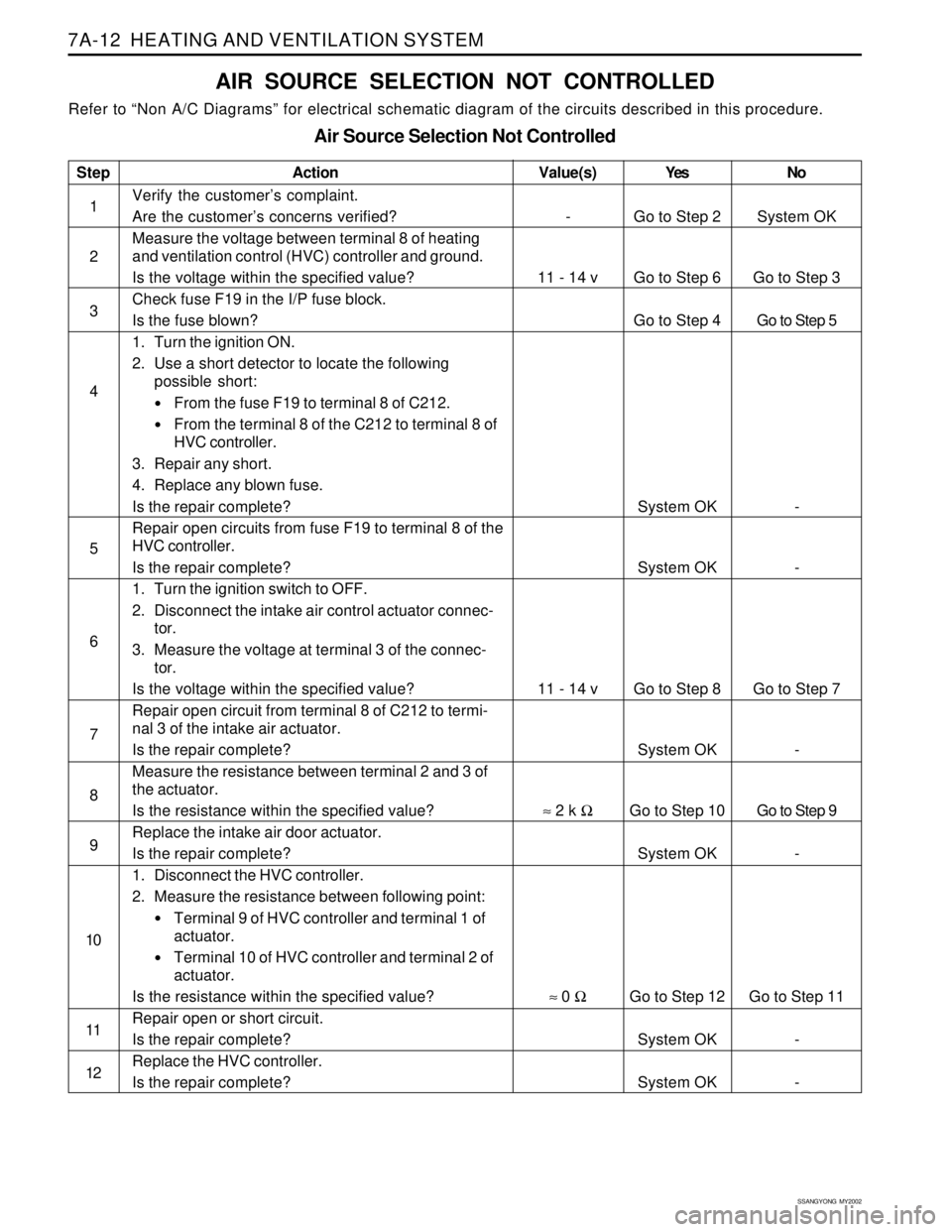
SSANGYONG MY2002
7A-12 HEATING AND VENTILATION SYSTEM
AIR SOURCE SELECTION NOT CONTROLLED
Refer to “Non A/C Diagrams” for electrical schematic diagram of the circuits described in this procedure.
Air Source Selection Not Controlled
Step
1
2
3
4
5
6
7
8
9
10
11
12Action
Verify the customer’s complaint.
Are the customer’s concerns verified?
Measure the voltage between terminal 8 of heating
and ventilation control (HVC) controller and ground.
Is the voltage within the specified value?
Check fuse F19 in the I/P fuse block.
Is the fuse blown?
1. Turn the ignition ON.
2. Use a short detector to locate the following
possible short:
From the fuse F19 to terminal 8 of C212.
From the terminal 8 of the C212 to terminal 8 of
HVC controller.
3. Repair any short.
4. Replace any blown fuse.
Is the repair complete?
Repair open circuits from fuse F19 to terminal 8 of the
HVC controller.
Is the repair complete?
1. Turn the ignition switch to OFF.
2. Disconnect the intake air control actuator connec-
tor.
3. Measure the voltage at terminal 3 of the connec-
tor.
Is the voltage within the specified value?
Repair open circuit from terminal 8 of C212 to termi-
nal 3 of the intake air actuator.
Is the repair complete?
Measure the resistance between terminal 2 and 3 of
the actuator.
Is the resistance within the specified value?
Replace the intake air door actuator.
Is the repair complete?
1. Disconnect the HVC controller.
2. Measure the resistance between following point:
Terminal 9 of HVC controller and terminal 1 of
actuator.
Terminal 10 of HVC controller and terminal 2 of
actuator.
Is the resistance within the specified value?
Repair open or short circuit.
Is the repair complete?
Replace the HVC controller.
Is the repair complete?Yes
Go to Step 2
Go to Step 6
Go to Step 4
System OK
System OK
Go to Step 8
System OK
Go to Step 10
System OK
Go to Step 12
System OK
System OKNo
System OK
Go to Step 3
Go to Step 5
-
-
Go to Step 7
-
Go to Step 9
-
Go to Step 11
-
-
Value(s)
-
11 - 14 v
11 - 14 v
≈ 2 k Ω
≈ 0 Ω
Page 1533 of 2053
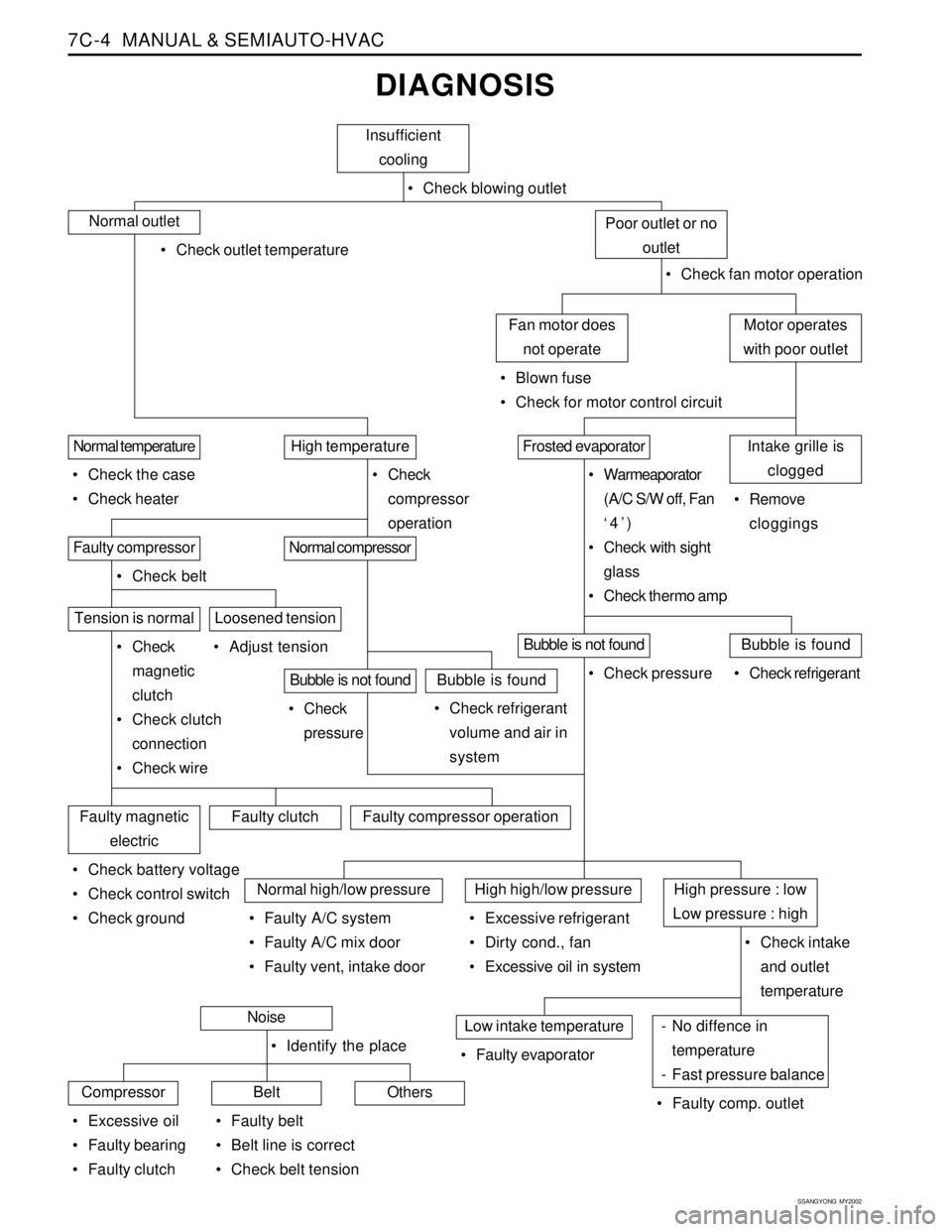
SSANGYONG MY2002
7C-4 MANUAL & SEMIAUTO-HVAC
DIAGNOSIS
Insufficient
cooling
Check blowing outlet
Normal outlet
Check outlet temperature
Check fan motor operation
Motor operates
with poor outletFan motor does
not operate
Blown fuse
Check for motor control circuit
Poor outlet or no
outlet
Intake grille is
cloggedFrosted evaporatorHigh temperatureNormal temperature
Check the case
Check heater Check
compressor
operation Warmeaporator
(A/C S/W off, Fan
‘4’)
Check with sight
glass
Check thermo amp Remove
cloggings
Normal compressorFaulty compressor
Check belt
Tension is normal
Check
magnetic
clutch
Check clutch
connection
Check wire Adjust tension
Bubble is not foundBubble is found
Check refrigerant
volume and air in
system Check
pressure
Loosened tension
Bubble is not foundBubble is found
Check refrigerant Check pressure
Faulty magnetic
electricFaulty clutchFaulty compressor operation
Check battery voltage
Check control switch
Check ground
Normal high/low pressureHigh high/low pressureHigh pressure : low
Low pressure : high
Check intake
and outlet
temperature Faulty A/C system
Faulty A/C mix door
Faulty vent, intake door Excessive refrigerant
Dirty cond., fan
Excessive oil in system
- No diffence in
temperature
- Fast pressure balanceLow intake temperature
Faulty comp. outlet Faulty evaporatorNoise
CompressorBeltOthers
Excessive oil
Faulty bearing
Faulty clutch Identify the place
Faulty belt
Belt line is correct
Check belt tension