Page 1362 of 2053
CLUTCH 5C-7
SSANGYONG MY2002
Removal & Installation Procedure
Tools Required
602589 00 40 00 Engine Lock
1. Remove the starter motor. Install the special tool
to the flywheel through the starter motor mounting
holes.
2. Unscren the release cylinder mounting bolts and
remove the release cylinder.
Installation Notice
3. Unscrew the clutch housing bolts and remove the
clutch housing, release fork and release bearing.
Installation Notice
4. Insert the centering pin into the clutch spline.
Loosen the clutch cover bolts 1/2 turn in crisscross
sequence until the spring tension is released.
Notice: Do not remove the bolts at a time, or
clutchcover can be damaged or deformed.
Tools Required
Centering Pin 661 589 00 15 00
KAA5C050
KAA5C060
KAA5C070
KAA5C080
Tightening Torque15 - 18 Nm
(11 - 13 lb-ft)
Tightening Torque 54 Nm (40 lb-ft)
Page 1363 of 2053
SSAMGYONG MY2002
5C-8 CLUTCH
5. Unscrew the bolts and remove the clutch cover,
pressure plate and clutch disc.
Notice: Be careful not to drop the pressure plate
and clutch disc.
Installation Notice
6. Installation should follow the removal procedure
in the reverse order.
Notice:
Before installation, clean oil and grease on the
flywheel surface.
Do not clean the clutch disc and release bearing
in solvent.
2. Clutch Disc
Check the facing for rivet looseness, excessive
runout, sticks, oil and grease.
Measure the rivet head depth.
If out limit, replace the disc.
Inspection Procedure
1. Clutch Cover
Check the diaphragm spring tip for wear and
height unevenness.
Check the pressure plate surface for wear, crack
and discoloration.
Check the strap plate rivet for looseness and
replace the clutch cover if loosened.
KAA5C090
KAA5C100
KAA5C110
Tightening Torque21 - 27 Nm
(15 - 20 lb-ft)
Wear Limit 0.3 mm
Unevenness Limit 0.8 mm
Page 1399 of 2053
TRANSFER CASE 5D1-77
SSANGYONG MY2002
KAA5D420
KAA5D590
23. Install the clutch coil and tighten three bolts.
Installation Notice
Caution: Do not kink or trap the wire while
seating the clutch coil to the case.
24. Install the pin on the tang end of the helical cam
into the hole in the front case.
25. Position the torsion spring tangs so that they are
pointing toward the top side of the transfer case
and just touching the high-low shift fork.
Caution: Do not bend the helical cam during
installation to the front case because of possible
damage to the pin at the tang end of the motor
shaft.
26. Install the shift rail through the high-low shift fork
and make sure that the reverse gear shift rail is
seated in the front case bore.
27. Install rear propeller shaft speed sensor toothed
wheel, vehicle speedometer gear and rear output
shaft seal if removed. Use oil seal installer or equiv-
alent.
Tightening Torque8 - 11 Nm
(6 - 8 lb-ft)
Page 1410 of 2053

SSANGYONG MY2002
5D2-10 TRANSFER CASE (PART TIME - 4408)
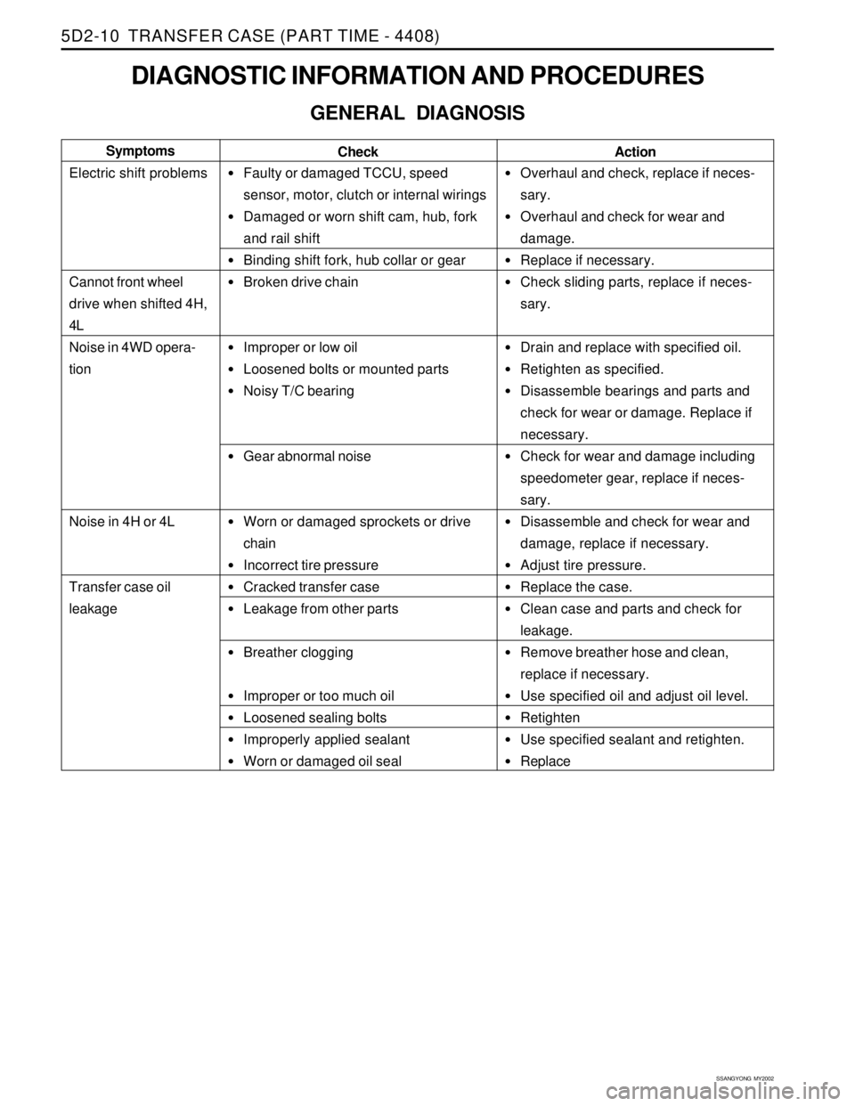
DIAGNOSTIC INFORMATION AND PROCEDURES
GENERAL DIAGNOSIS
Faulty or damaged TCCU, speed
sensor, motor, clutch or internal wirings
Damaged or worn shift cam, hub, fork
and rail shift
Binding shift fork, hub collar or gear
Broken drive chain
Improper or low oil
Loosened bolts or mounted parts
Noisy T/C bearing
Gear abnormal noise
Worn or damaged sprockets or drive
chain
Incorrect tire pressure
Cracked transfer case
Leakage from other parts
Breather clogging
Improper or too much oil
Loosened sealing bolts
Improperly applied sealant
Worn or damaged oil seal
Overhaul and check, replace if neces-
sary.
Overhaul and check for wear and
damage.
Replace if necessary.
Check sliding parts, replace if neces-
sary.
Drain and replace with specified oil.
Retighten as specified.
Disassemble bearings and parts and
check for wear or damage. Replace if
necessary.
Check for wear and damage including
speedometer gear, replace if neces-
sary.
Disassemble and check for wear and
damage, replace if necessary.
Adjust tire pressure.
Replace the case.
Clean case and parts and check for
leakage.
Remove breather hose and clean,
replace if necessary.
Use specified oil and adjust oil level.
Retighten
Use specified sealant and retighten.
Replace Check Symptoms
Electric shift problems
Cannot front wheel
drive when shifted 4H,
4L
Noise in 4WD opera-
tion
Noise in 4H or 4L
Transfer case oil
leakage
Action
Page 1472 of 2053

SSANGYONG MY2002
6C-4 POWER STEERING GEAR
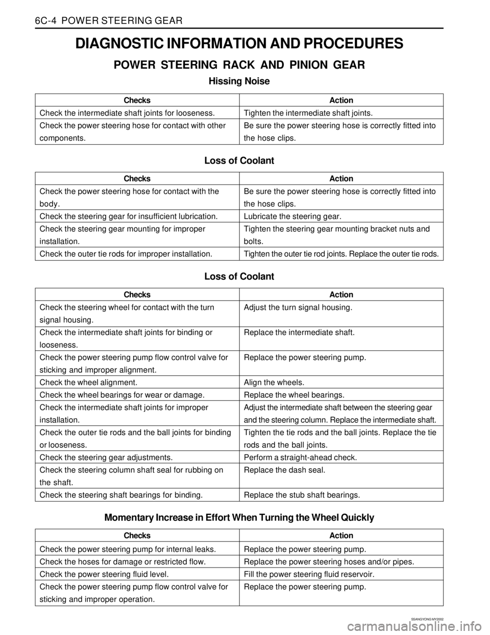
DIAGNOSTIC INFORMATION AND PROCEDURES
POWER STEERING RACK AND PINION GEAR
Hissing Noise
Check the intermediate shaft joints for looseness.
Check the power steering hose for contact with other
components.ChecksActionTighten the intermediate shaft joints.
Be sure the power steering hose is correctly fitted into
the hose clips.
Loss of Coolant
Check the power steering hose for contact with the
body.
Check the steering gear for insufficient lubrication.
Check the steering gear mounting for improper
installation.
Check the outer tie rods for improper installation.ChecksActionBe sure the power steering hose is correctly fitted into
the hose clips.
Lubricate the steering gear.
Tighten the steering gear mounting bracket nuts and
bolts.
Tighten the outer tie rod joints. Replace the outer tie rods.
Loss of Coolant
Check the steering wheel for contact with the turn
signal housing.
Check the intermediate shaft joints for binding or
looseness.
Check the power steering pump flow control valve for
sticking and improper alignment.
Check the wheel alignment.
Check the wheel bearings for wear or damage.
Check the intermediate shaft joints for improper
installation.
Check the outer tie rods and the ball joints for binding
or looseness.
Check the steering gear adjustments.
Check the steering column shaft seal for rubbing on
the shaft.
Check the steering shaft bearings for binding.ChecksActionAdjust the turn signal housing.
Replace the intermediate shaft.
Replace the power steering pump.
Align the wheels.
Replace the wheel bearings.
Adjust the intermediate shaft between the steering gear
and the steering column. Replace the intermediate shaft.
Tighten the tie rods and the ball joints. Replace the tie
rods and the ball joints.
Perform a straight-ahead check.
Replace the dash seal.
Replace the stub shaft bearings.
Check the power steering pump for internal leaks.
Check the hoses for damage or restricted flow.
Check the power steering fluid level.
Check the power steering pump flow control valve for
sticking and improper operation.ChecksActionReplace the power steering pump.
Replace the power steering hoses and/or pipes.
Fill the power steering fluid reservoir.
Replace the power steering pump.
Momentary Increase in Effort When Turning the Wheel Quickly
Page 1473 of 2053

POWER STEERING GEAR 6C-5
SSANGYONG MY2002
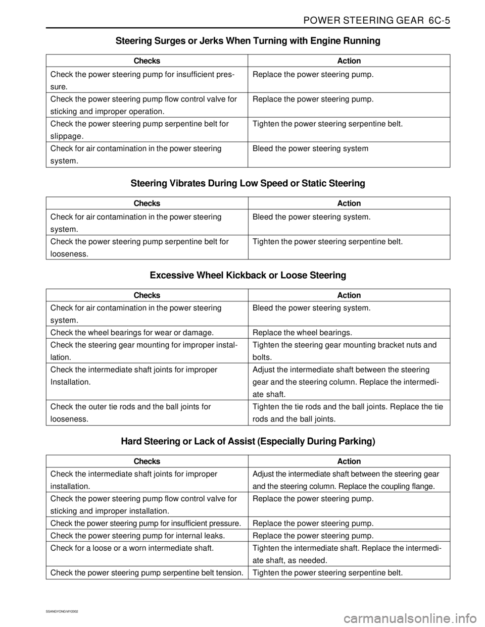
Check the power steering pump for insufficient pres-
sure.
Check the power steering pump flow control valve for
sticking and improper operation.
Check the power steering pump serpentine belt for
slippage.
Check for air contamination in the power steering
system.ChecksActionReplace the power steering pump.
Replace the power steering pump.
Tighten the power steering serpentine belt.
Bleed the power steering system
Steering Surges or Jerks When Turning with Engine Running
Check for air contamination in the power steering
system.
Check the power steering pump serpentine belt for
looseness.ChecksActionBleed the power steering system.
Tighten the power steering serpentine belt.
Steering Vibrates During Low Speed or Static Steering
Excessive Wheel Kickback or Loose Steering
Check for air contamination in the power steering
system.
Check the wheel bearings for wear or damage.
Check the steering gear mounting for improper instal-
lation.
Check the intermediate shaft joints for improper
Installation.
Check the outer tie rods and the ball joints for
looseness.ChecksActionBleed the power steering system.
Replace the wheel bearings.
Tighten the steering gear mounting bracket nuts and
bolts.
Adjust the intermediate shaft between the steering
gear and the steering column. Replace the intermedi-
ate shaft.
Tighten the tie rods and the ball joints. Replace the tie
rods and the ball joints.
Hard Steering or Lack of Assist (Especially During Parking)
Check the intermediate shaft joints for improper
installation.
Check the power steering pump flow control valve for
sticking and improper installation.
Check the power steering pump for insufficient pressure.
Check the power steering pump for internal leaks.
Check for a loose or a worn intermediate shaft.
Check the power steering pump serpentine belt tension.ChecksActionAdjust the intermediate shaft between the steering gear
and the steering column. Replace the coupling flange.
Replace the power steering pump.
Replace the power steering pump.
Replace the power steering pump.
Tighten the intermediate shaft. Replace the intermedi-
ate shaft, as needed.
Tighten the power steering serpentine belt.
Page 1477 of 2053
POWER STEERING GEAR 6C-9
SSANGYONG MY2002
KAA6C140
KAA6C050
KAA6C050
6. Remove the outer tie rod nuts and disconnect the
tie rod ends from the knuckle using the ball joint
remover 661 589 13 33 00.
Installation Notice
7. Remove the rack and pinion assembly mounting
bolts and remove therackand pinion assembly.
Installation Notice
Tightening Torque 40 Nm (30 lb-ft)
After installing the rack and pinion assembly,
bleed the power steering system. Refer to
Section 6A, Power Steering System.
OUTER TIE ROD
Tools Required
661589 13 33 00 BallJointRemover
Removal and Installation Procedure
1. Remove the wheel. Refer to Section 2E, Tires and
wheels.
2. Mark the threads on the inner tie rod to aid in
repositioning the adjusting nut.
3. Remove the outer tie rod nut and disconnect the
outer tie rod from the knuckle using the ball joint
remover 661 589 13 33 00.
Installation Notice
Tightening Torque 78 Nm (58 lb-ft)
Tightening Torque 40 Nm (30 lb-ft)
Page 1488 of 2053

SSANGYONG MY2002
6E-2 POWER STEERING AND COLUMN
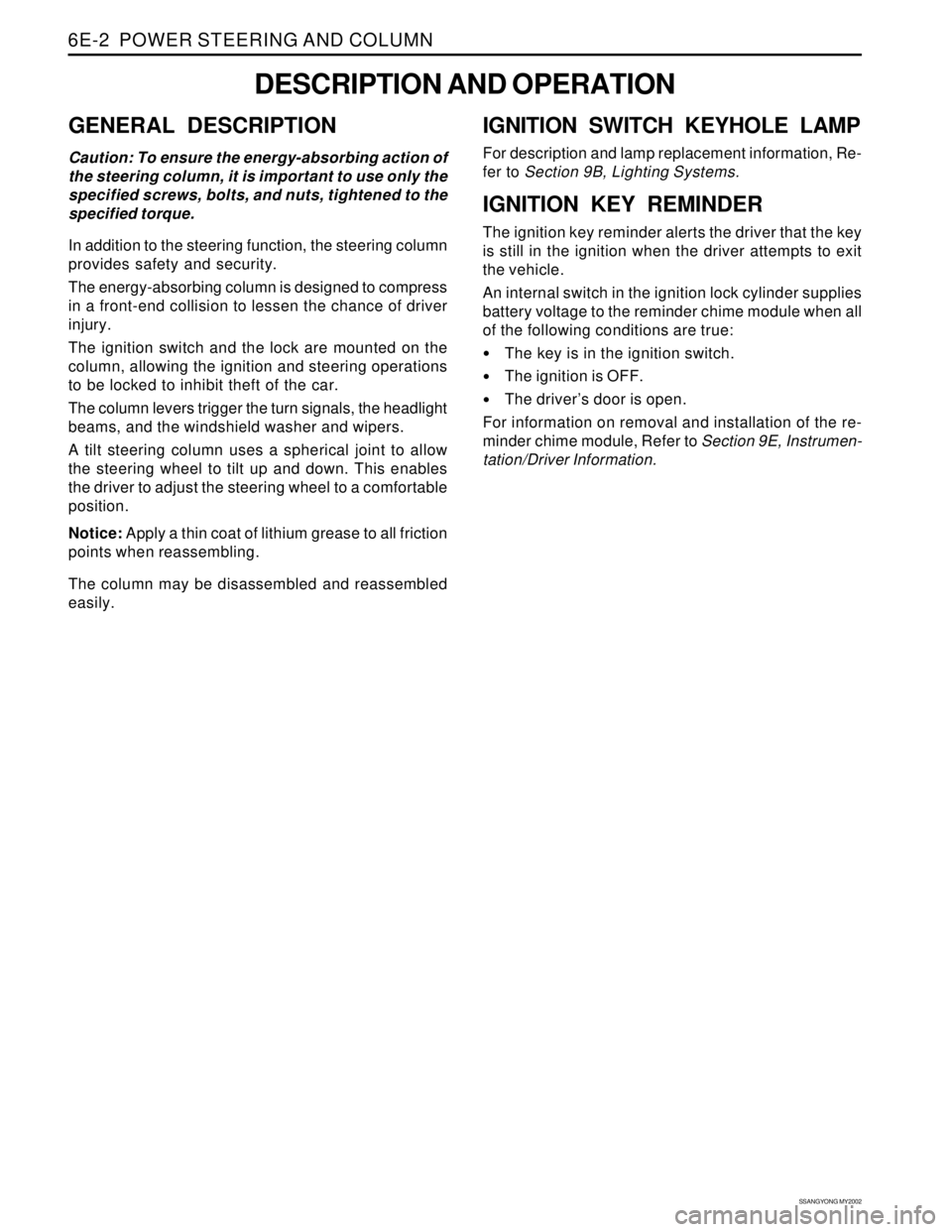
GENERAL DESCRIPTION
Caution: To ensure the energy-absorbing action of
the steering column, it is important to use only the
specified screws, bolts, and nuts, tightened to the
specified torque.
In addition to the steering function, the steering column
provides safety and security.
The energy-absorbing column is designed to compress
in a front-end collision to lessen the chance of driver
injury.
The ignition switch and the lock are mounted on the
column, allowing the ignition and steering operations
to be locked to inhibit theft of the car.
The column levers trigger the turn signals, the headlight
beams, and the windshield washer and wipers.
A tilt steering column uses a spherical joint to allow
the steering wheel to tilt up and down. This enables
the driver to adjust the steering wheel to a comfortable
position.
Notice: Apply a thin coat of lithium grease to all friction
points when reassembling.
The column may be disassembled and reassembled
easily.
DESCRIPTION AND OPERATION
IGNITION SWITCH KEYHOLE LAMP
For description and lamp replacement information, Re-
fer to Section 9B, Lighting Systems.
IGNITION KEY REMINDER
The ignition key reminder alerts the driver that the key
is still in the ignition when the driver attempts to exit
the vehicle.
An internal switch in the ignition lock cylinder supplies
battery voltage to the reminder chime module when all
of the following conditions are true:
•The key is in the ignition switch.
The ignition is OFF.
The driver’s door is open.
For information on removal and installation of the re-
minder chime module, Refer to Section 9E, Instrumen-
tation/Driver Information.