1997 SSANGYONG KORANDO tire pressure
[x] Cancel search: tire pressurePage 987 of 2053
ABS AND TCS 4F-3
SSANGYONG MY2002
GENERAL DESCRIPTION AND SYSTEM OPERATION
BASIC KNOWLEDGE REQUIRED
Before using this section, it is important that you have
a basic knowledge of the following items. Without this
knowledge, it will be difficult to use the diagnostic
procedures contained in this section.
•Basic Electrical Circuits - You should understand
the basic theory of electricity and know the meaning
of voltage, current (amps), and resistance (ohms).
You should understand what happens in a circuit
with an open or shorted wire. You should be able to
read and understand a wiring diagram.
Use of Circuit Testing Tools - You should know
how to use a test light and how to bypass
components to test circuits using fused jumper
wires. You should be familiar with a digital
multimeter. You should be able to measure voltage,
resistance, and current, and be familiar with the
controls and how to use them correctly.
ABS SYSTEM COMPONENTS
The ABS 5.3 Antilock Braking System (ABS) consists
of a conventional hydraulic brake system plus antilock
components. The conventional brake system includes
a vacuum booster, master cylinder, front disc brakes,
rear disc brakes, interconnecting hydraulic brake pipes
and hoses, brake fluid level switch and the BRAKE
indicator.
The ABS components include a hydraulic unit, an elec-
tronic brake control module (EBCM), two system fuses,
four wheel speed sensors (one at each wheel), intercon-
necting wiring, the ABS indicator, the EBD indicator
and the TCS indicator. See “ABS Component Locator”
in this section for the general layout of this system.
The hydraulic unit with the attached EBCM is located
between the surge tank and the bulkhead on the left
side of the vehicle.
The basic hydraulic unit configuration consists of hy-
draulic check valves, two solenoid valves for each
wheel, a hydraulic pump, and two accumulators. The
hydraulic unit controls hydraulic pressure to the front
calipers and rear calipers by modulating hydraulic
pressure to prevent wheel lockup.
Units equipped with TCS add two more valves for each
drive wheel for the purpose of applying the brake to a
wheel that is slipping. This is done with pressure from
the hydraulic pump in the unit. There is also a TCS
indicator lamp on the instrument panel to alert the driver
to the fact that the TCS system is active. The
components identified in the drawing are those added
to the basic ABS 5.3 system to provide traction control.
Nothing in the hydraulic unit or the EBCM is serviceable.
In the event of any failure, the entire ABS unit withattached EBCM must be replaced. For more
information, refer to “Base Braking Mode” and
“Antilock Braking Mode” in this section.
TRACTION CONTROL SYSTEM
(TCS) DESCRIPTION
General Information
The traction control system (TCS) is a traction system
by means of brake intervention only, available in a low
speed range (< 60kph).
It workes on µ - split roads with sidewise different friction
coefficients.
The spinning driven wheel is braked and the drive
torque can be transferred to the wheel on the high-µ
side. During TCS active, the TCS information lamp is
blinking.
The temperature of the brakes is calculated by a mathe-
matical model and TCS is switched passive if the calcu-
lated temperature is greater than a threshold value (500
°C).
TCS is permitted again, when the calculated tempera-
ture is less than 350 °C.
Control Algorithm
The input signals for the control algorithm are the
filtered wheel speed signals from the ABS speed
processing.
With the speed difference of the driven wheels, the
control deviation is calculated.
If the control deviation exceeds a certain threshold
value, the wheel with the greater slip is braked actively.
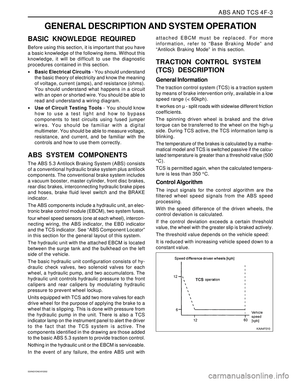
The threshold value depends on the vehicle speed:
It is reduced with increasing vehicle speed down to a
constant value.
KAA4F010
Page 1410 of 2053
SSANGYONG MY2002
5D2-10 TRANSFER CASE (PART TIME - 4408)
DIAGNOSTIC INFORMATION AND PROCEDURES
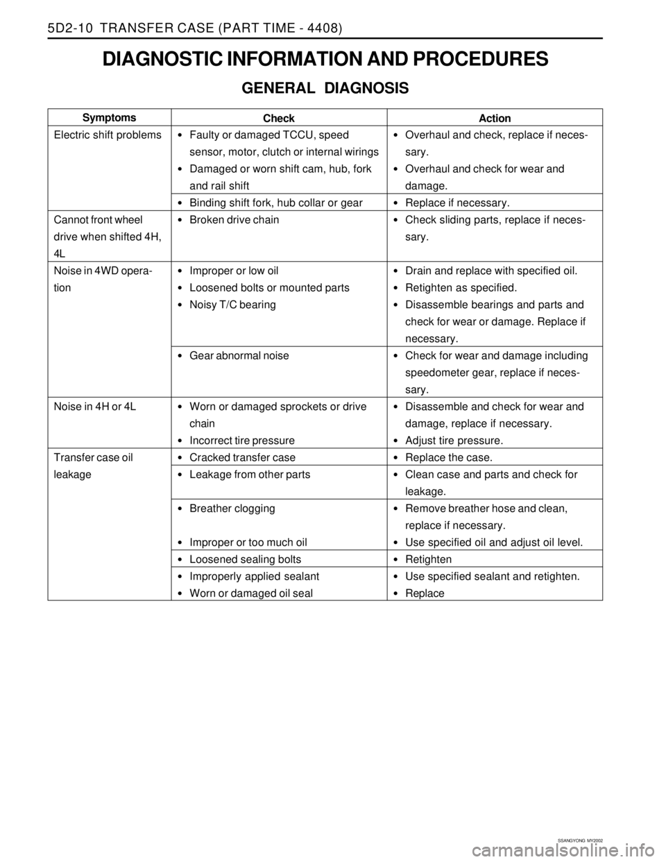
GENERAL DIAGNOSIS
Faulty or damaged TCCU, speed
sensor, motor, clutch or internal wirings
Damaged or worn shift cam, hub, fork
and rail shift
Binding shift fork, hub collar or gear
Broken drive chain
Improper or low oil
Loosened bolts or mounted parts
Noisy T/C bearing
Gear abnormal noise
Worn or damaged sprockets or drive
chain
Incorrect tire pressure
Cracked transfer case
Leakage from other parts
Breather clogging
Improper or too much oil
Loosened sealing bolts
Improperly applied sealant
Worn or damaged oil seal
Overhaul and check, replace if neces-
sary.
Overhaul and check for wear and
damage.
Replace if necessary.
Check sliding parts, replace if neces-
sary.
Drain and replace with specified oil.
Retighten as specified.
Disassemble bearings and parts and
check for wear or damage. Replace if
necessary.
Check for wear and damage including
speedometer gear, replace if neces-
sary.
Disassemble and check for wear and
damage, replace if necessary.
Adjust tire pressure.
Replace the case.
Clean case and parts and check for
leakage.
Remove breather hose and clean,
replace if necessary.
Use specified oil and adjust oil level.
Retighten
Use specified sealant and retighten.
Replace Check Symptoms
Electric shift problems
Cannot front wheel
drive when shifted 4H,
4L
Noise in 4WD opera-
tion
Noise in 4H or 4L
Transfer case oil
leakage
Action
Page 1474 of 2053
SSANGYONG MY2002
6C-6 POWER STEERING GEAR
POWER STEERING RACK AND
PINION GEAR BENCH TESTING
Removal and Installation Procedure
Notice: Pressure checks or pressure and flow checks
may also be conducted using this setup.
1. Disconnect and remove the power steering gear.
Refer to “Rack and Pinion Assembly” in this
section.
2. Place the power steering gear on a bench next to
the vehicle.
3. Disconnect the pressure line at the point where the
hose connects to the pipe. Extend this line to reach
the power steering gear on the bench.
4. Disconnect the return line from the power steering
fluid reservoir. Extend this line to reach the power
steering gear on the bench.
5. Connect the power steering pipes to the power
steering gear.
6. Start the engine and allow it to idle for 10 seconds.
7. Check the power steering fluid level. Refer to
Section 6A, Power Steering System.
8. Start the engine and turn the rack and pinion stub
shaft a full turn in each direction. Hold the shaft
against each stop for 5 seconds.
9. Inspect for possible leak points. Refer to Section
6A, Power Steering System.
Installation Procedure
1. Stop the engine.
2. Disconnect the power steering pipes from the power
steering gear.
KAA6C020
3. Remove the extensions and reconnect the pressure
and return lines.
4. Install and connect the power steering gear. Refer
to “Rack and Pinion Assembly” in this section.
5. Start the engine and allow it to idle for 10 seconds.
6. Check the power steering fluid level. Refer to
Section 6A, Power Steering System.
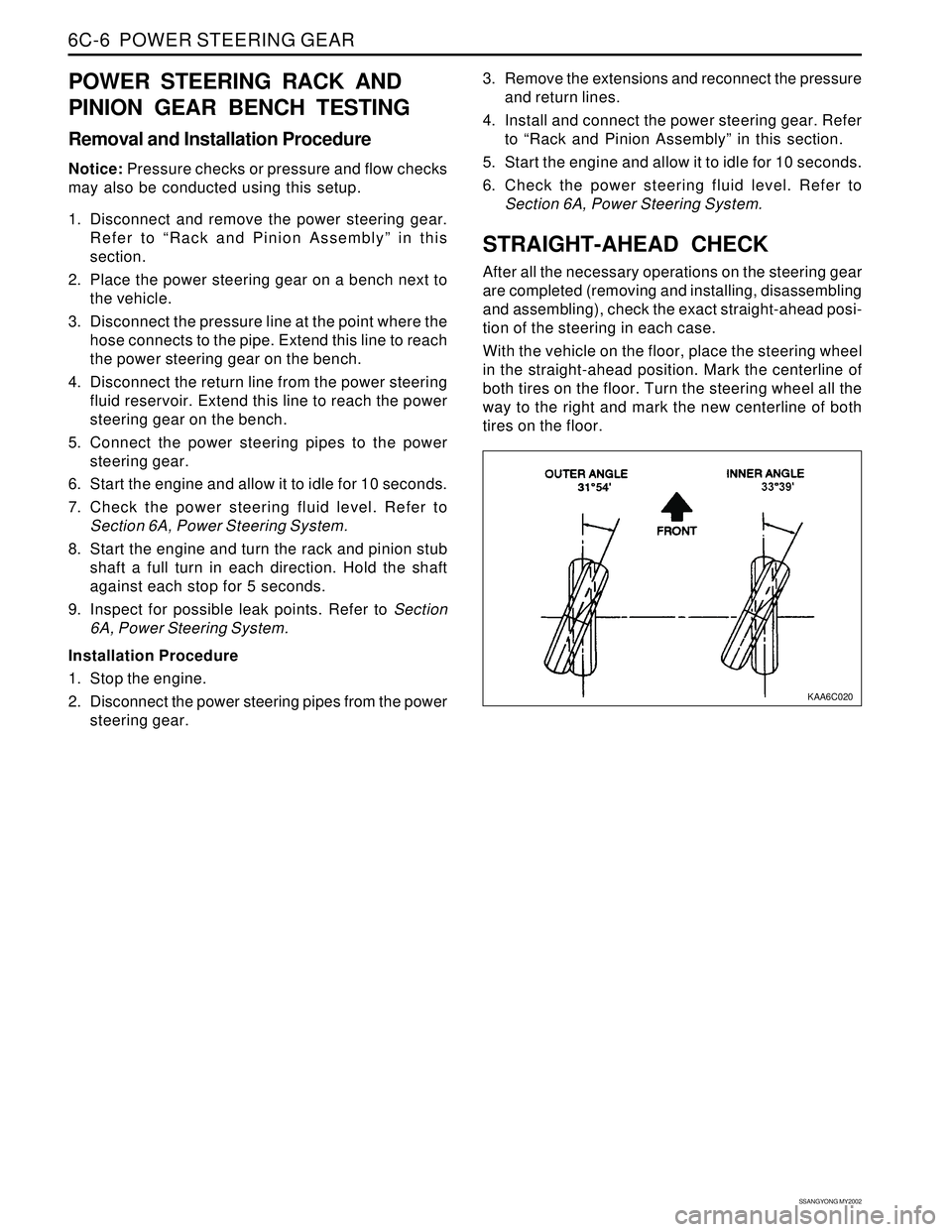
STRAIGHT-AHEAD CHECK
After all the necessary operations on the steering gear
are completed (removing and installing, disassembling
and assembling), check the exact straight-ahead posi-
tion of the steering in each case.
With the vehicle on the floor, place the steering wheel
in the straight-ahead position. Mark the centerline of
both tires on the floor. Turn the steering wheel all the
way to the right and mark the new centerline of both
tires on the floor.
Page 1476 of 2053
SSANGYONG MY2002
6C-8 POWER STEERING GEAR
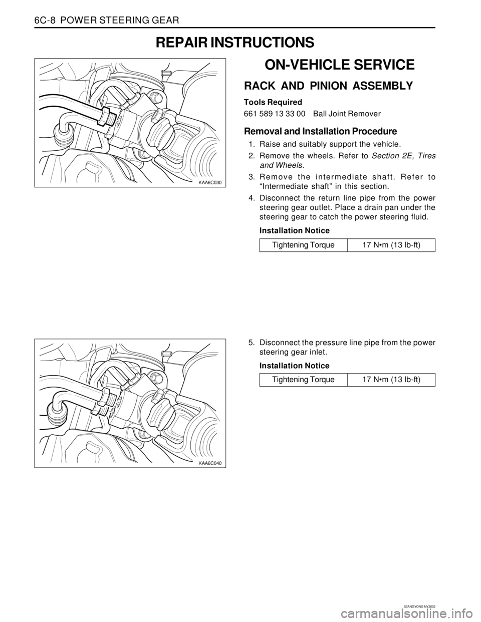
KAA6C040
KAA6C030
ON-VEHICLE SERVICE
RACK AND PINION ASSEMBLY
Tools Required
661 589 13 33 00 Ball Joint Remover
Removal and Installation Procedure
1. Raise and suitably support the vehicle.
2. Remove the wheels. Refer to Section 2E, Tires
and Wheels.
3. Remove the intermediate shaft. Refer to
“Intermediate shaft” in this section.
4. Disconnect the return line pipe from the power
steering gear outlet. Place a drain pan under the
steering gear to catch the power steering fluid.
Installation Notice
REPAIR INSTRUCTIONS
Tightening Torque 17 Nm (13 lb-ft)
5. Disconnect the pressure line pipe from the power
steering gear inlet.
Installation Notice
Tightening Torque 17 Nm (13 lb-ft)
Page 1771 of 2053
WATERLEAKS 9I-3
SSANGYONG MY2002
DIAGNOSIS
WATERLEAK DIAGNOSIS
The repair of waterleaks in the body requires proper
testing and diagnosis. Repair waterleaks by adjusting
the misaligned parts and using the proper repair materi-
als. First, determine what conditions cause the leak.
For example, the leak may occur only when the vehicle
is parked on an incline, or water may appear only in
the spare tire compartment. Second, test the area for
the source of the leak using the following testing
methods. If the general leak area is found, determine
the exact entry point of the leak by using a water hose
or an air hose. If the general leak area is not obvious,
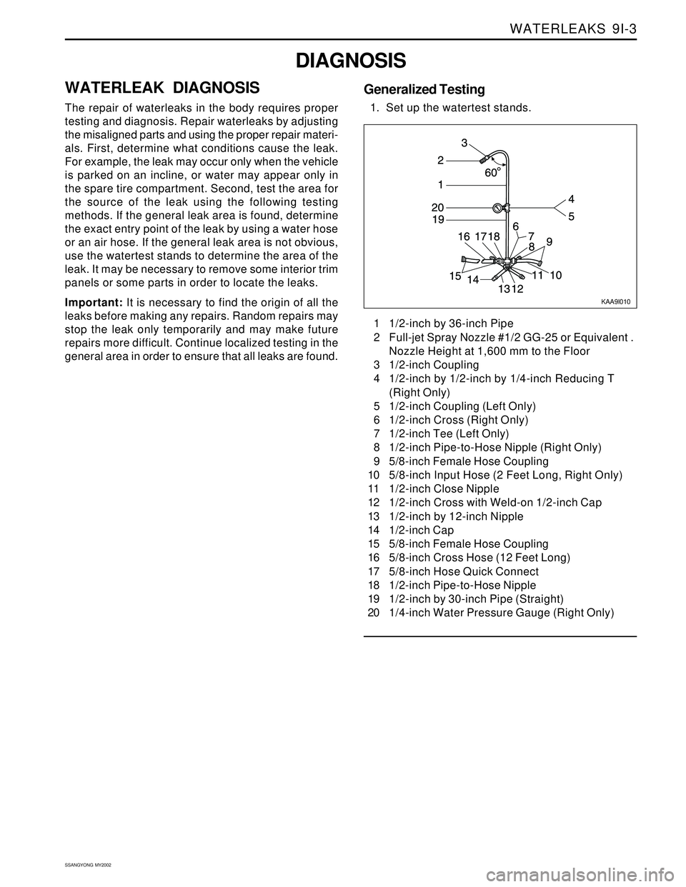
use the watertest stands to determine the area of the
leak. It may be necessary to remove some interior trim
panels or some parts in order to locate the leaks.
Important: It is necessary to find the origin of all the
leaks before making any repairs. Random repairs may
stop the leak only temporarily and may make future
repairs more difficult. Continue localized testing in the
general area in order to ensure that all leaks are found.1 1/2-inch by 36-inch Pipe
2 Full-jet Spray Nozzle #1/2 GG-25 or Equivalent .
Nozzle Height at 1,600 mm to the Floor
3 1/2-inch Coupling
4 1/2-inch by 1/2-inch by 1/4-inch Reducing T
(Right Only)
5 1/2-inch Coupling (Left Only)
6 1/2-inch Cross (Right Only)
7 1/2-inch Tee (Left Only)
8 1/2-inch Pipe-to-Hose Nipple (Right Only)
9 5/8-inch Female Hose Coupling
10 5/8-inch Input Hose (2 Feet Long, Right Only)
11 1/2-inch Close Nipple
12 1/2-inch Cross with Weld-on 1/2-inch Cap
13 1/2-inch by 12-inch Nipple
14 1/2-inch Cap
15 5/8-inch Female Hose Coupling
16 5/8-inch Cross Hose (12 Feet Long)
17 5/8-inch Hose Quick Connect
18 1/2-inch Pipe-to-Hose Nipple
19 1/2-inch by 30-inch Pipe (Straight)
20 1/4-inch Water Pressure Gauge (Right Only)
KAA9I010
Generalized Testing
1. Set up the watertest stands.