1997 SSANGYONG KORANDO heater
[x] Cancel search: heaterPage 1506 of 2053
HEATING AND VENTILATION SYSTEM 7A-5
SSANGYONG MY2002
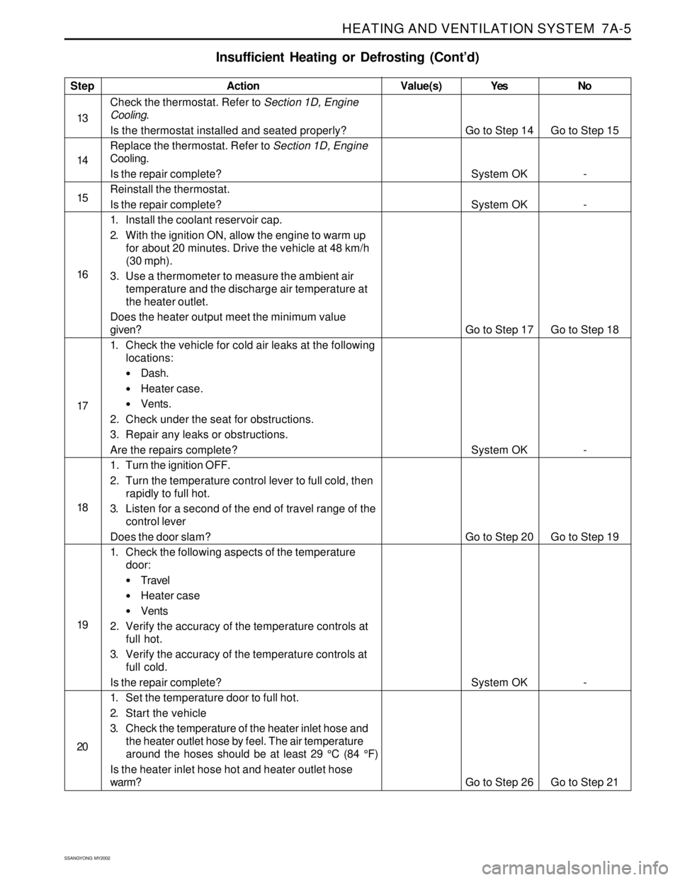
Insufficient Heating or Defrosting (Cont’d)
Step
13
14
15
16
17
18
19
20Action
Check the thermostat. Refer to Section 1D, Engine
Cooling.
Is the thermostat installed and seated properly?
Replace the thermostat. Refer to Section 1D, Engine
Cooling.
Is the repair complete?
Reinstall the thermostat.
Is the repair complete?
1. Install the coolant reservoir cap.
2. With the ignition ON, allow the engine to warm up
for about 20 minutes. Drive the vehicle at 48 km/h
(30 mph).
3. Use a thermometer to measure the ambient air
temperature and the discharge air temperature at
the heater outlet.
Does the heater output meet the minimum value
given?
1. Check the vehicle for cold air leaks at the following
locations:
Dash.
Heater case.
Vents.
2. Check under the seat for obstructions.
3. Repair any leaks or obstructions.
Are the repairs complete?
1. Turn the ignition OFF.
2. Turn the temperature control lever to full cold, then
rapidly to full hot.
3. Listen for a second of the end of travel range of the
control lever
Does the door slam?
1. Check the following aspects of the temperature
door:
Travel
Heater case
Vents
2. Verify the accuracy of the temperature controls at
full hot.
3. Verify the accuracy of the temperature controls at
full cold.
Is the repair complete?
1. Set the temperature door to full hot.
2. Start the vehicle
3. Check the temperature of the heater inlet hose and
the heater outlet hose by feel. The air temperature
around the hoses should be at least 29 °C (84 °F)
Is the heater inlet hose hot and heater outlet hose
warm?Yes
Go to Step 14
System OK
System OK
Go to Step 17
System OK
Go to Step 20
System OK
Go to Step 26No
Go to Step 15
-
-
Go to Step 18
-
Go to Step 19
-
Go to Step 21 Value(s)
Page 1507 of 2053
SSANGYONG MY2002
7A-6 HEATING AND VENTILATION SYSTEM
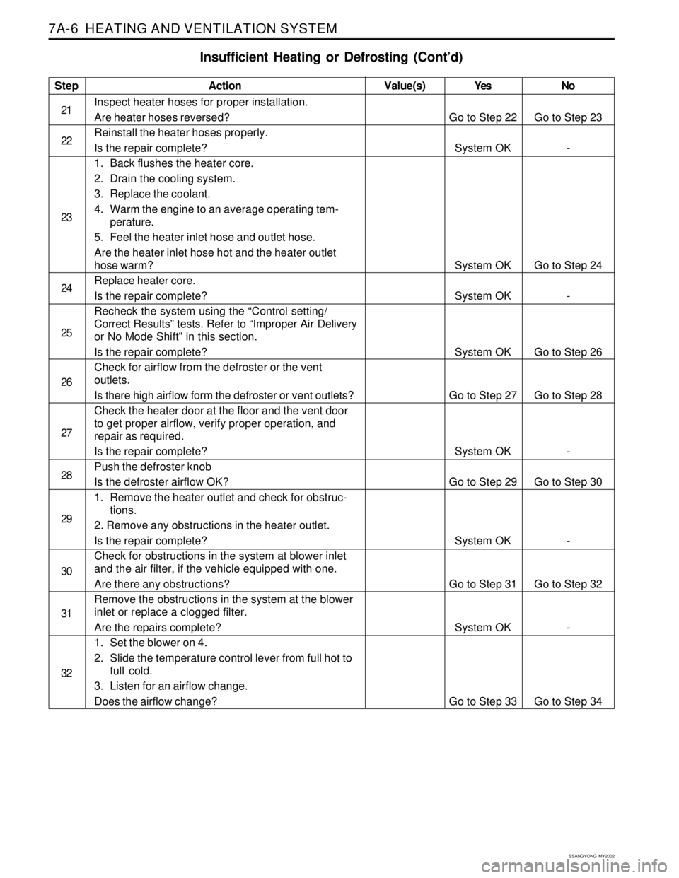
Insufficient Heating or Defrosting (Cont’d)
Step
21
22
23
24
25
26
27
28
29
30
31
32Action
Inspect heater hoses for proper installation.
Are heater hoses reversed?
Reinstall the heater hoses properly.
Is the repair complete?
1. Back flushes the heater core.
2. Drain the cooling system.
3. Replace the coolant.
4. Warm the engine to an average operating tem-
perature.
5. Feel the heater inlet hose and outlet hose.
Are the heater inlet hose hot and the heater outlet
hose warm?
Replace heater core.
Is the repair complete?
Recheck the system using the “Control setting/
Correct Results” tests. Refer to “Improper Air Delivery
or No Mode Shift” in this section.
Is the repair complete?
Check for airflow from the defroster or the vent
outlets.
Is there high airflow form the defroster or vent outlets?
Check the heater door at the floor and the vent door
to get proper airflow, verify proper operation, and
repair as required.
Is the repair complete?
Push the defroster knob
Is the defroster airflow OK?
1. Remove the heater outlet and check for obstruc-
tions.
2. Remove any obstructions in the heater outlet.
Is the repair complete?
Check for obstructions in the system at blower inlet
and the air filter, if the vehicle equipped with one.
Are there any obstructions?
Remove the obstructions in the system at the blower
inlet or replace a clogged filter.
Are the repairs complete?
1. Set the blower on 4.
2. Slide the temperature control lever from full hot to
full cold.
3. Listen for an airflow change.
Does the airflow change?Yes
Go to Step 22
System OK
System OK
System OK
System OK
Go to Step 27
System OK
Go to Step 29
System OK
Go to Step 31
System OK
Go to Step 33No
Go to Step 23
-
Go to Step 24
-
Go to Step 26
Go to Step 28
-
Go to Step 30
-
Go to Step 32
-
Go to Step 34 Value(s)
Page 1515 of 2053
SSANGYONG MY2002
7A-14 HEATING AND VENTILATION SYSTEM
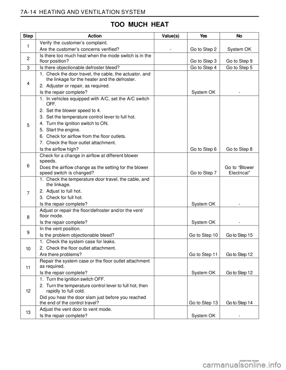
TOO MUCH HEAT
Step
1
2
3
4
5
6
7
8
9
10
11
12
13Action
Verify the customer’s complaint.
Are the customer’s concerns verified?
Is there too much heat when the mode switch is in the
floor position?
Is there objectionable defroster bleed?
1. Check the door travel, the cable, the actuator, and
the linkage for the heater and the defroster.
2. Adjuster or repair, as required.
Is the repair complete?
1. In vehicles equipped with A/C, set the A/C switch
OFF.
2. Set the blower speed to 4.
3. Set the temperature control lever to full hot.
4. Turn the ignition switch to ON.
5. Start the engine.
6. Check for airflow from the floor outlets.
7. Check the floor outlet attachment.
Is the airflow high?
Check for a change in airflow at different blower
speeds.
Does the airflow change as the setting for the blower
speed switch is changed?
1. Check the temperature door travel, the cable, and
the linkage.
2. Adjust to full hot.
3. Check for full hot.
Is the repair complete?
Adjust or repair the floor/defroster and/or the vent/
floor mode.
Is the repair complete?
In the vent position.
Is the problem objectionable bleed?
1. Check the system case for leaks.
2. Check the floor outlet attachment.
Are there problems?
Repair the system case or the floor outlet attachment
as required.
Is the repair complete?
1. Turn the ignition switch OFF.
2. Turn the temperature control lever to full hot, then
rapidly to full cold.
Did you hear the door slam just before you reached
the end of the control travel?
Adjust the vent door to vent mode.
Is the repair complete?Yes
Go to Step 2
Go to Step 3
Go to Step 4
System OK
Go to Step 6
Go to Step 7
System OK
System OK
Go to Step 10
Go to Step 11
System OK
Go to Step 13
System OKNo
System OK
Go to Step 9
Go to Step 5
-
Go to Step 8
Go to “Blower
Electrical”
-
-
Go to Step 15
Go to Step 12
Go to Step 12
Go to Step 14
-Value(s)
-
Page 1519 of 2053
SSANGYONG MY2002
7A-18 HEATING AND VENTILATION SYSTEM
ON-VEHICLE SERVICE
TEMPREATURE CONTROL CABLE
ADJUSTMENT
Because the cable and the cable housing have fixed
lengths, it is impossible to make a temperature cable
adjustment.
The heater/air distributor case linkage also cannot be
adjusted.
If a malfunction is suspected, verify the proper
operation of the controller and the mechanical doors
for heater/air distributor case assembly.
MAINTENANCE AND REPAIR
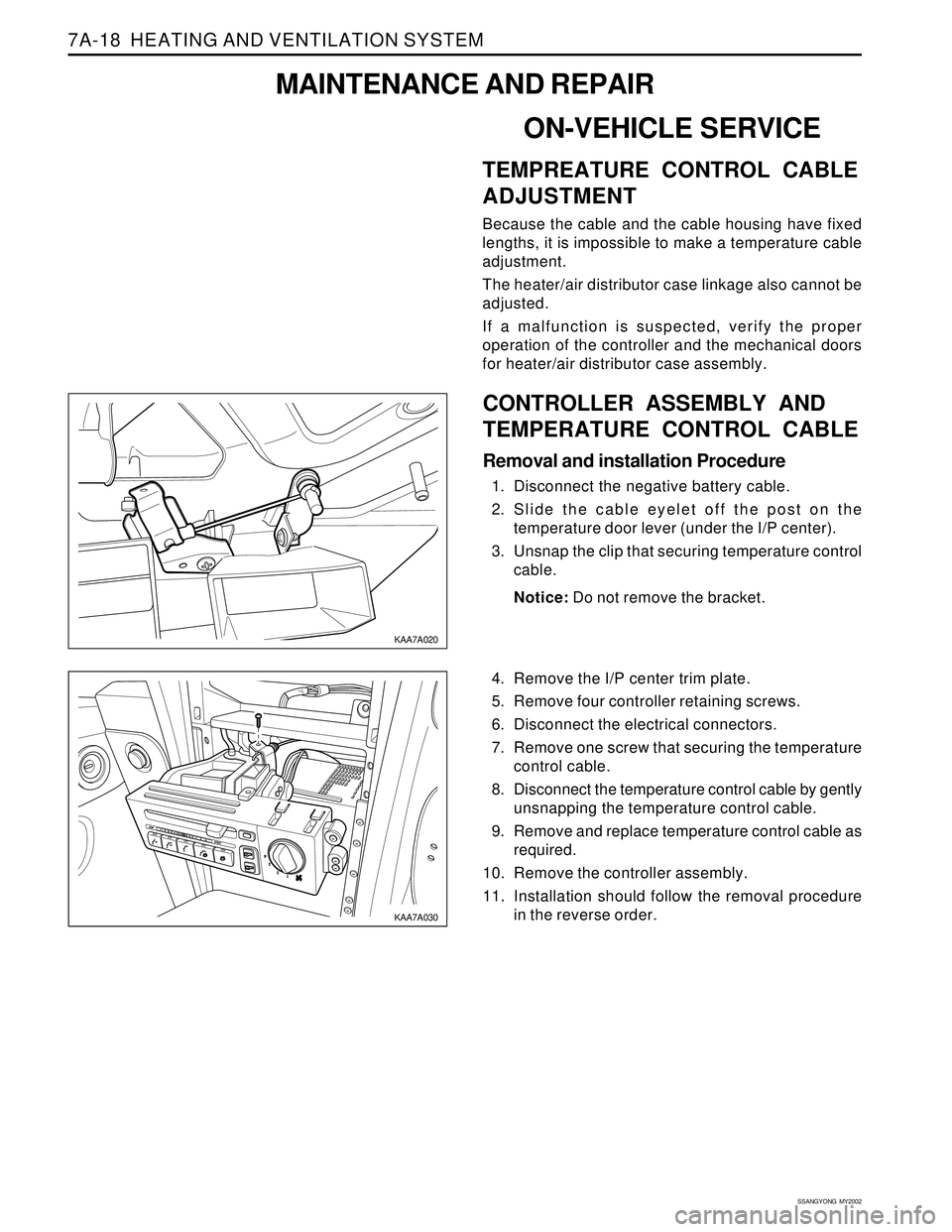
KAA7A020
KAA7A030
CONTROLLER ASSEMBLY AND
TEMPERATURE CONTROL CABLE
Removal and installation Procedure
1. Disconnect the negative battery cable.
2. Slide the cable eyelet off the post on the
temperature door lever (under the I/P center).
3. Unsnap the clip that securing temperature control
cable.
Notice: Do not remove the bracket.
4. Remove the I/P center trim plate.
5. Remove four controller retaining screws.
6. Disconnect the electrical connectors.
7. Remove one screw that securing the temperature
control cable.
8. Disconnect the temperature control cable by gently
unsnapping the temperature control cable.
9. Remove and replace temperature control cable as
required.
10. Remove the controller assembly.
11. Installation should follow the removal procedure
in the reverse order.
Page 1520 of 2053
HEATING AND VENTILATION SYSTEM 7A-19
SSANGYONG MY2002
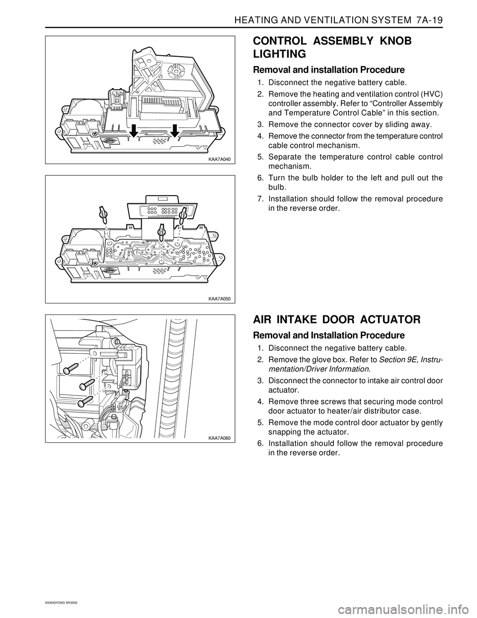
CONTROL ASSEMBLY KNOB
LIGHTING
Removal and installation Procedure
1. Disconnect the negative battery cable.
2. Remove the heating and ventilation control (HVC)
controller assembly. Refer to “Controller Assembly
and Temperature Control Cable” in this section.
3. Remove the connector cover by sliding away.
4. Remove the connector from the temperature control
cable control mechanism.
5. Separate the temperature control cable control
mechanism.
6. Turn the bulb holder to the left and pull out the
bulb.
7. Installation should follow the removal procedure
in the reverse order.
KAA7A040
KAA7A050
KAA7A060
AIR INTAKE DOOR ACTUATOR
Removal and Installation Procedure
1. Disconnect the negative battery cable.
2. Remove the glove box. Refer to Section 9E, Instru-
mentation/Driver Information.
3. Disconnect the connector to intake air control door
actuator.
4. Remove three screws that securing mode control
door actuator to heater/air distributor case.
5. Remove the mode control door actuator by gently
snapping the actuator.
6. Installation should follow the removal procedure
in the reverse order.
Page 1521 of 2053
SSANGYONG MY2002
7A-20 HEATING AND VENTILATION SYSTEM
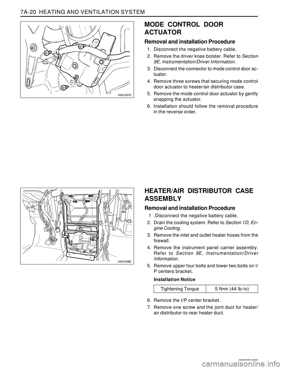
MODE CONTROL DOOR
ACTUATOR
Removal and installation Procedure
1. Disconnect the negative battery cable.
2. Remove the driver knee bolster. Refer to Section
9E, Instrumentation/Driver Information.
3. Disconnect the connector to mode control door ac-
tuator.
4. Remove three sxrews that securing mode control
door actuator to heater/air distributor case.
5. Remove the mode control door actuator by gently
snapping the actuator.
6. Installation should follow the removal procedure
in the reverse order.
Tightening Torque 5 Nm (44 lb-in)
KAA7A070
KAA7A080
HEATER/AIR DISTRIBUTOR CASE
ASSEMBLY
Removal and installation Procedure
1 .Disconnect the negative battery cable.
2. Drain the cooling system. Refer to Section 1D, En-
gine Cooling.
3. Remove the inlet and outlet heater hoses from the
firewall.
4. Remove the instrument panel carrier assembly.
Refer to Section 9E, Instrumentation/Driver
Information.
5. Remove upper four bolts and lower two bolts on I/
P centers bracket.
Installation Notice
6. Remove the I/P center bracket.
7. Remove one screw and the joint duct for heater/
air distributor-to-rear heater duct.
Page 1522 of 2053
HEATING AND VENTILATION SYSTEM 7A-21
SSANGYONG MY2002
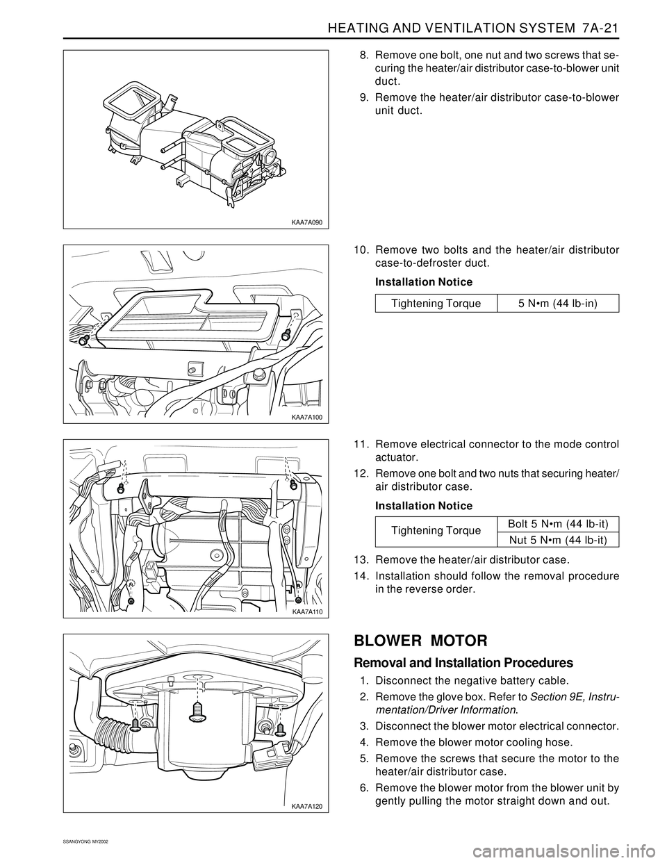
8. Remove one bolt, one nut and two screws that se-
curing the heater/air distributor case-to-blower unit
duct.
9. Remove the heater/air distributor case-to-blower
unit duct.
KAA7A090
KAA7A100
KAA7A110
KAA7A120
10. Remove two bolts and the heater/air distributor
case-to-defroster duct.
Installation Notice
11. Remove electrical connector to the mode control
actuator.
12. Remove one bolt and two nuts that securing heater/
air distributor case.
Installation Notice
13. Remove the heater/air distributor case.
14. Installation should follow the removal procedure
in the reverse order.
Tightening TorqueBolt 5 Nm (44 lb-it)
Nut 5 Nm (44 lb-it)
BLOWER MOTOR
Removal and Installation Procedures
1. Disconnect the negative battery cable.
2. Remove the glove box. Refer to Section 9E, Instru-
mentation/Driver Information.
3. Disconnect the blower motor electrical connector.
4. Remove the blower motor cooling hose.
5. Remove the screws that secure the motor to the
heater/air distributor case.
6. Remove the blower motor from the blower unit by
gently pulling the motor straight down and out.
Tightening Torque 5 Nm (44 lb-in)
Page 1523 of 2053
SSANGYONG MY2002
7A-22 HEATING AND VENTILATION SYSTEM
7. Installation should follow the removal procedure
in the reverse order.
Installation Notice: After install the blower motor
confirm that the blower motor operates properly.
KAA7A130
KAA7A140
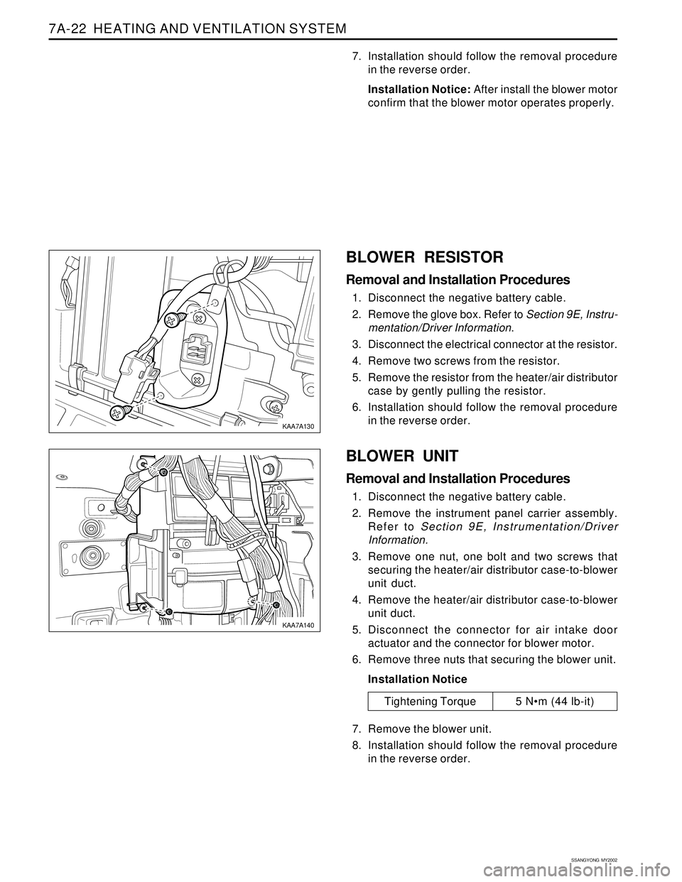
BLOWER RESISTOR
Removal and Installation Procedures
1. Disconnect the negative battery cable.
2. Remove the glove box. Refer to Section 9E, Instru-
mentation/Driver Information.
3. Disconnect the electrical connector at the resistor.
4. Remove two screws from the resistor.
5. Remove the resistor from the heater/air distributor
case by gently pulling the resistor.
6. Installation should follow the removal procedure
in the reverse order.
BLOWER UNIT
Removal and Installation Procedures
1. Disconnect the negative battery cable.
2. Remove the instrument panel carrier assembly.
Refer to Section 9E, Instrumentation/Driver
Information.
3. Remove one nut, one bolt and two screws that
securing the heater/air distributor case-to-blower
unit duct.
4. Remove the heater/air distributor case-to-blower
unit duct.
5. Disconnect the connector for air intake door
actuator and the connector for blower motor.
6. Remove three nuts that securing the blower unit.
Installation Notice
7. Remove the blower unit.
8. Installation should follow the removal procedure
in the reverse order.
Tightening Torque 5 Nm (44 lb-it)