Page 1478 of 2053

SSANGYONG MY2002
6C-10 POWER STEERING GEAR
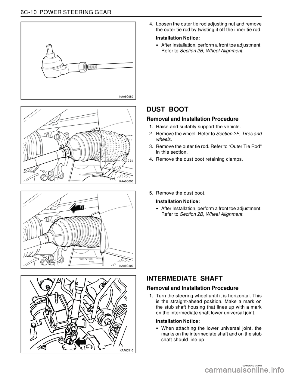
KAA6C090
KAA6C100
KAA6C110
KAA6C080
4. Loosen the outer tie rod adjusting nut and remove
the outer tie rod by twisting it off the inner tie rod.
Installation Notice:
After Installation, perform a front toe adjustment.
Refer to Section 2B, Wheel Alignment.
DUST BOOT
Removal and Installation Procedure
1. Raise and suitably support the vehicle.
2. Remove the wheel. Refer to Section 2E, Tires and
wheels.
3. Remove the outer tie rod. Refer to “Outer Tie Rod”
in this section.
4. Remove the dust boot retaining clamps.
5. Remove the dust boot.
Installation Notice:
After Installation, perform a front toe adjustment.
Refer to Section 2B, Wheel Alignment.
INTERMEDIATE SHAFT
Removal and Installation Procedure
1. Turn the steering wheel until it is horizontal. This
is the straight-ahead position. Make a mark on
the stub shaft housing that lines up with a mark
on the intermediate shaft lower universal joint.
Installation Notice:
When attaching the lower universal joint, the
marks on the intermediate shaft and on the stub
shaft should line up
Page 1481 of 2053

POWER STEERING GEAR 6C-13
SSANGYONG MY2002
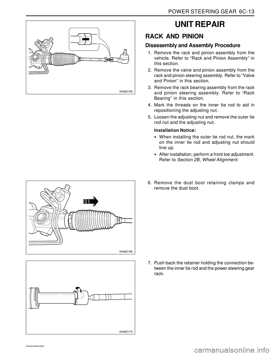
KAA6C150
UNIT REPAIR
RACK AND PINION
Disassembly and Assembly Procedure
1. Remove the rack and pinion assembly from the
vehicle. Refer to “Rack and Pinion Assembly” in
this section.
2. Remove the valve and pinion assembly from the
rack and pinion steering assembly. Refer to “Valve
and Pinion” in this section.
3. Remove the rack bearing assembly from the rack
and pinion steering assembly. Refer to “Rack
Bearing” in this section.
4. Mark the threads on the inner tie rod to aid in
repositioning the adjusting nut.
5. Loosen the adjusting nut and remove the outer tie
rod nut and the adjusting nut.
Installation Notice:
When installing the outer tie rod nut, the mark
on the inner tie rod and adjusting nut should
line up.
After installation, perform a front toe adjustment.
Refer to Section 2B, Wheel Alignment.
KAA6C160
KAA6C170
6. Remove the dust boot retaining clamps and
remove the dust boot.
7. Push back the retainer holding the connection be-
tween the inner tie rod and the power steering gear
rack.
Page 1752 of 2053
INTERIOR TRIM 9G-3
SSANGYONG MY2002
COMPONENTS LOCATOR
INTERIOR TRIM
1 Console Box
2 Tray
3 Arm Rest
4 Parking Lever Strip
5 Facia (BTRA A/T)
6 Indicator Cover7 Facia (M/T)
8 Boot Assembly (M/T)
9 Facia (MB A/T)
10 Rear Facia Strip
11 Rear Facia Cap
KAA9G010
Page 1781 of 2053

SQUEAKS AND RATTLES 9K-3
SSANGYONG MY2002
Check for a lack of lubrication of the door hinge pins.ChecksActionOperate the doors and listen for squeaks.
Lubricate the door hinge pins with light oil and coat
with lithium grease.
Squeak Coming From Console When Shifting Manual Transaxle
(Condition Occurs In Cold Weather with a Cold Engine)
Check the manual transaxle control lever lower boot.ChecksActionMove the control lever between gears and listen for
squeaks.
Remove the floor console and replace the lower shift
boot or apply talcum powder to the lower shift boot.
Squeak When Operating Doors
Check for vibration of the fuse box cover against the
instrument panel side trim.ChecksActionTap on thecoverwith a fingerandlisten fora buzz.
Apply 6.35 mm (0.250 inch) by 25.4 mm (1.00 inch)
felt pads to the side trim where the cover makes
contact.
Squeak Coming From Instrument Cluster Trim Plate
Check for rubbing of the cluster trim plate on the
instrument panel.ChecksActionTest drive the vehicle in order to verify this condi-
tion.
Remove the instrument cluster trim plate and install
felt tape to the edges.
Buzz From the Left Side of Instrument Panel
Check the door lock solenoid.
Check for rattling electrical connectors inside the door
trim panel.ChecksActionRemove the door trim panel and check if the sole-
noid is loose.
Tighten the solenoid bolts.
Tap on the trim panel and listen for a rattle.
Remove the trim panel and wrap foam padding
around the connectors as required.
Rattle Coming From Door
Page:
< prev 1-8 9-16 17-24