Page 982 of 2053
SSANGYONG MY2002
4E-22 REAR BRAKES
UNIT REPAIR
WHEEL CYLINDER
Disassembly Procedure
1. Remove the upper brake return spring and remove
the wheel cylinder with pulling the upper lining
outside.
2. Disassembly the wheel cylinder assembly.
Remove the dust boot and do not reuse them
(1).
Remove the piston (2).
Remove the piston cup and do not reuse it (3).
Remove the spring assembly (4).
Remove the bleeder screw (5).
3. Clean all the parts with the denatured alcohol. Dry
the parts with unlubricated compressed air.
Bleeder Screw7 - 10 Nm
(62 - 89 lb-in)
8 - 12 Nm
(71 - 106 lb-in)
Wheel Cylinder
Mounting Bolt
Notice: Lubricate the new seals, the piston, the
piston cup and the wheel cylinder bore with clean
brake fluid before assembly. 4. Installation should follow the removal procedure
in the reverse order.
5. Tighten the bleeder screw and wheel cylinder as
specified torque.
YAD4C460
YAD4C470
YAD4C480
Page 1092 of 2053

PARKING BRAKE 4G-5
SSANGYONG MY2002
KAA4G040
KAA4G050
KAA4G060
KAA4G070
PARKING BRAKE LEVER
Removal and Installation Procedure
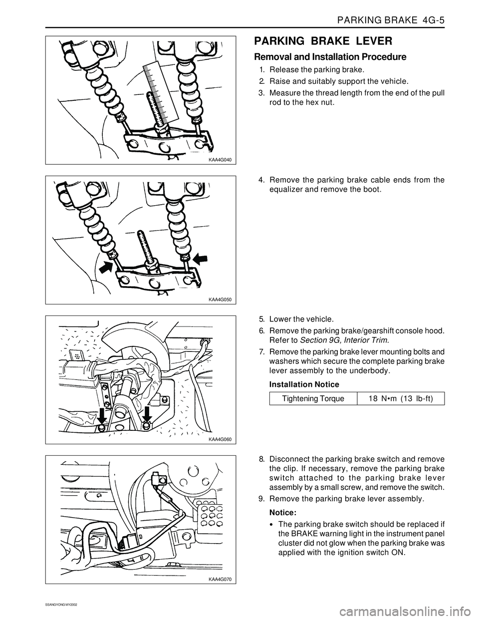
1. Release the parking brake.
2. Raise and suitably support the vehicle.
3. Measure the thread length from the end of the pull
rod to the hex nut.
5. Lower the vehicle.
6. Remove the parking brake/gearshift console hood.
Refer to Section 9G, Interior Trim.
7. Remove the parking brake lever mounting bolts and
washers which secure the complete parking brake
lever assembly to the underbody.
Installation Notice
8. Disconnect the parking brake switch and remove
the clip. If necessary, remove the parking brake
switch attached to the parking brake lever
assembly by a small screw, and remove the switch.
9. Remove the parking brake lever assembly.
Notice:
The parking brake switch should be replaced if
the BRAKE warning light in the instrument panel
cluster did not glow when the parking brake was
applied with the ignition switch ON.
Tightening Torque 18 Nm (13 lb-ft) 4. Remove the parking brake cable ends from the
equalizer and remove the boot.
Page 1317 of 2053
MANUAL TRANSMISSION 5B-9
SSANGYONG MY2002
SEMI-REMOTE KIT DISASSEMBLY AND ASSEMBLY
YAD5B110
1 Remote Shift
2 Shift Lever
3 Shift Inner Boot
4 Lining Shift Socket
5 Control Housing Arm Insulator
6 Control Housing Arm
7 Bushing
8 Shift Rod Link
9 Washer
10 Clip
11 Shift Rod Pin
12 Cover Assembly
13 Shift Tower Cover14 Bolt
15 Breather Hose Bar
16 Control Shift Spring
17 Offset Control Lever
18 Retainer Ring
19 Pin
20 Shift Rail
21 Grove Pin
22 Pin & Clip
23 Joint Assembly
24 Joint Housing
25 Bushing
Page 1320 of 2053

SSANGYONG MY2002
5B-12 MANUAL TRANSMISSION
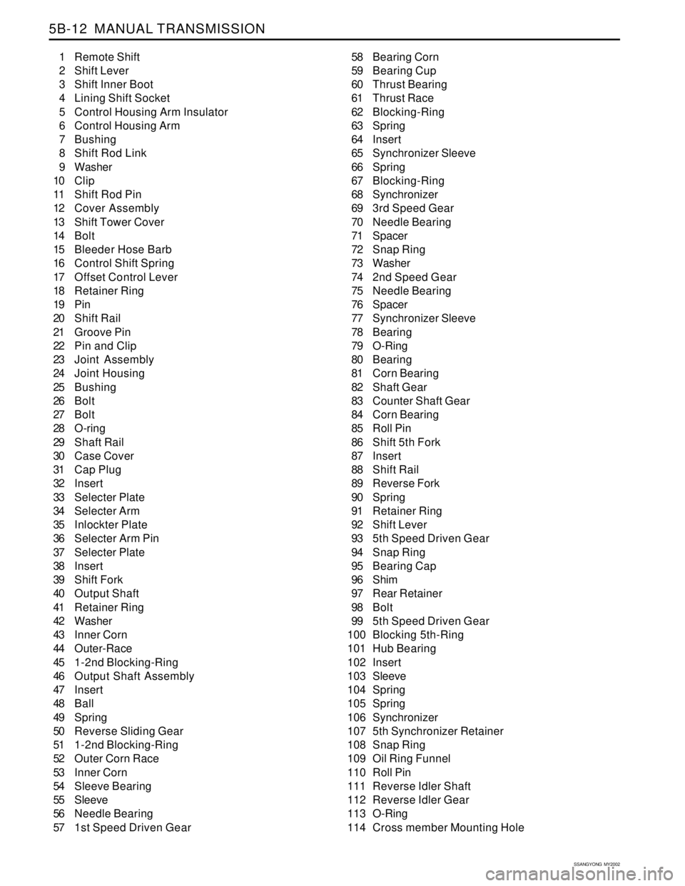
1 Remote Shift
2 Shift Lever
3 Shift Inner Boot
4 Lining Shift Socket
5 Control Housing Arm Insulator
6 Control Housing Arm
7 Bushing
8 Shift Rod Link
9 Washer
10 Clip
11 Shift Rod Pin
12 Cover Assembly
13 Shift Tower Cover
14 Bolt
15 Bleeder Hose Barb
16 Control Shift Spring
17 Offset Control Lever
18 Retainer Ring
19 Pin
20 Shift Rail
21 Groove Pin
22 Pin and Clip
23 Joint Assembly
24 Joint Housing
25 Bushing
26 Bolt
27 Bolt
28 O-ring
29 Shaft Rail
30 Case Cover
31 Cap Plug
32 Insert
33 Selecter Plate
34 Selecter Arm
35 Inlockter Plate
36 Selecter Arm Pin
37 Selecter Plate
38 Insert
39 Shift Fork
40 Output Shaft
41 Retainer Ring
42 Washer
43 Inner Corn
44 Outer-Race
45 1-2nd Blocking-Ring
46 Output Shaft Assembly
47 Insert
48 Ball
49 Spring
50 Reverse Sliding Gear
51 1-2nd Blocking-Ring
52 Outer Corn Race
53 Inner Corn
54 Sleeve Bearing
55 Sleeve
56 Needle Bearing
57 1st Speed Driven Gear58 Bearing Corn
59 Bearing Cup
60 Thrust Bearing
61 Thrust Race
62 Blocking-Ring
63 Spring
64 Insert
65 Synchronizer Sleeve
66 Spring
67 Blocking-Ring
68 Synchronizer
69 3rd Speed Gear
70 Needle Bearing
71 Spacer
72 Snap Ring
73 Washer
74 2nd Speed Gear
75 Needle Bearing
76 Spacer
77 Synchronizer Sleeve
78 Bearing
79 O-Ring
80 Bearing
81 Corn Bearing
82 Shaft Gear
83 Counter Shaft Gear
84 Corn Bearing
85 Roll Pin
86 Shift 5th Fork
87 Insert
88 Shift Rail
89 Reverse Fork
90 Spring
91 Retainer Ring
92 Shift Lever
93 5th Speed Driven Gear
94 Snap Ring
95 Bearing Cap
96 Shim
97 Rear Retainer
98 Bolt
99 5th Speed Driven Gear
100 Blocking 5th-Ring
101 Hub Bearing
102 Insert
103 Sleeve
104 Spring
105 Spring
106 Synchronizer
107 5th Synchronizer Retainer
108 Snap Ring
109 Oil Ring Funnel
110 Roll Pin
111 Reverse Idler Shaft
112 Reverse Idler Gear
113 O-Ring
114 Cross member Mounting Hole
Page 1359 of 2053
CLUTCH 5C-3
SSANGYONG MY2002
1 Clutch Disc
2 Clutch Cover
3 Clutch Housing
4 Release Bearing
5 Release Fork Pivot
6 Release Cylinder
7 Release Fork Boot
COMPONENT LOCATOR
CLUTCH ASSEMBLY
8 Bolt
9 Release Fork
10 Bolt
11 Spring Lock Washer
12 Transmission Input Spline
13 Release Bearing Contacting Surface
14 Contacting Point of Release Fork and Pivot
KAA5C010
Notice: Apply the long-term grease (DBL 6811.00) to No.12,13 and 14.
Page 1365 of 2053
SSAMGYONG MY2002
5C-10 CLUTCH
1 Snap Pin
2 Clevis Pin
3 Clevis
4 Lock Nut
5 Flange Nut.................... 8 - 18 Nm (6 - 13 lb-ft)
6 Push Rod
7 Cylinder Body
8 Oil Pipe..................... 15 - 18 Nm (11 - 13 lb-ft)
MASTER CYLINDER
9 Clamp
10 Reservoir
11 Spring
12 Piston Assembly
13 Boot
14 Plate
15 Snap Ring
KAA5C130
Notice: Do not disassemble the No. 12.
Page 1469 of 2053

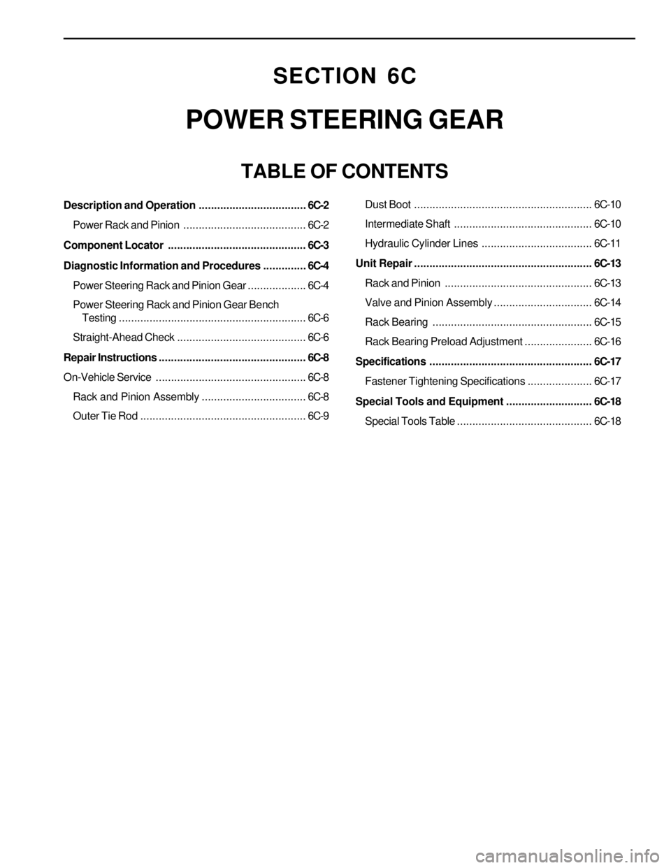
SECTION 6C
POWER STEERING GEAR
TABLE OF CONTENTS
Description and Operation...................................6C-2
Power Rack and Pinion........................................6C-2
Component Locator.............................................6C-3
Diagnostic Information and Procedures..............6C-4
Power Steering Rack and Pinion Gear...................6C-4
Power Steering Rack and Pinion Gear Bench
Testing.............................................................6C-6
Straight-Ahead Check ..........................................6C-6
Repair Instructions................................................6C-8
On-Vehicle Service.................................................6C-8
Rack and Pinion Assembly..................................6C-8
Outer Tie Rod......................................................6C-9Dust Boot.......................................................... 6C-10
Intermediate Shaft............................................. 6C-10
Hydraulic Cylinder Lines.................................... 6C-11
Unit Repair.......................................................... 6C-13
Rack and Pinion................................................ 6C-13
Valve and Pinion Assembly................................ 6C-14
Rack Bearing.................................................... 6C-15
Rack Bearing Preload Adjustment...................... 6C-16
Specifications..................................................... 6C-17
Fastener Tightening Specifications..................... 6C-17
Special Tools and Equipment............................ 6C-18
Special Tools Table............................................ 6C-18
Page 1471 of 2053
POWER STEERING GEAR 6C-3
SSANGYONG MY2002
COMPONENT LOCATOR
KAA6C010
1 Intermediate Shaft
2 Lower Pinch Bolt
3 Boot
4 Outer Tie Rod
5 Return Line Pipe6 Rack and Pinion Assembly
7 Rack and Pinion Assembly Mounting Bolt
8 Castle Nut
9 Cotter Pin
10 Pressure Line Pipe