Page 988 of 2053

SSANGYONG MY2002
4F-4 ABS AND TCS
Pressure Modulation
Depending on the control deviation and the wheel accel-
eration of the spinning wheel, pressure increase, hold
and decrease are made.
The pressure modulation is done with the conventional
control with the valves. Prime valve, pilot valve, inlet
valve and outlet valve according to the following table:
Speed Range
TCS is available in the speed range ≤ 60 kph.
Above 60 kph vehicle speed, TCS is passive.
It is possible to initiate TCS operation up to a vehicle
speed of 55 kph.
Prime Valve
Pilot Valve
Inlet Valve
Outlet Valve
Increase
Open
Closed
Open
ClosedHold
Open
Closed
Closed
ClosedDecrease
Open
Closed
Closed
Open
System Failure (EBD,
ABS or TCS are Not
Distinguished)
ABS Warning
LampIgnition ONABS
OperationTCS
OperationTCS Passive Due to
Temperature Model
2 second on
for lamp
checkOFF OFF ON OFF
TCS Info
Lamp2 second on
for lamp
checkOFFBlinking
(FLASHING)OFF ON
EBD Warning
Lamp2 second on
for lamp
checkEBD
operation/OFFOFF ON OFF
Temperature Model
TCS operation is a high thermal load for the brakes.
To avoid any damages at the brakes, the disk tempera-
ture is calculated with a mathematical model for each
driven wheel separately. After ignition on, the
calculation starts with 30°C and then three different
phases are evaluated separately and added:
TCS operation, braking and coling phase.
If the temperature is highter than 500°C, TCS is dis-
abled for this wheel.
It is permitted again, if the model has calculated down
the 350°C.
Lamp Concepts
The system is equipped with an TCS information lamp,
which is blinking during TCS operation.
The activation of the EBD, TCS warning lamp and the
TCS info lamp issummarized in thefollowing table:
Page 997 of 2053
SSANGYONG MY2002
4F-14 ABS AND TCS
COMPONENT LOCATOR
ABS, ABS/TCS 5.3
1 ABS/TCS Hydraulic Unit
(with EBCM in case of ABS only)
2 ABS/TCS EBCM Unit (in case of TCS)
3 Rear Wheel Speed Sensor
KAA4F100
4 ABS Warning Indicator Light
5 Diagnosis Connector
6 Front Wheel Speed Sensor
7 Acceleration Sensor
Page 1001 of 2053
SSANGYONG MY2002
4F-18 ABS AND TCS
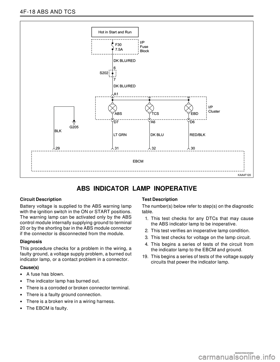
ABS INDICATOR LAMP INOPERATIVE
KAA4F120
Circuit Description
Battery voltage is supplied to the ABS warning lamp
with the ignition switch in the ON or START positions.
The warning lamp can be activated only by the ABS
control module internally supplying ground to terminal
20 or by the shorting bar in the ABS module connector
if the connector is disconnected from the module.
Diagnosis
This procedure checks for a problem in the wiring, a
faulty ground, a voltage supply problem, a burned out
indicator lamp, or a contact problem in a connector.
Cause(s)
A fuse has blown.
The indicator lamp has burned out.
There is a corroded or broken connector terminal.
There is a faulty ground connection.
There is a broken wire in a wiring harness.
The EBCM is faulty.Test Description
The number(s) below refer to step(s) on the diagnostic
table.
1. This test checks for any DTCs that may cause
the ABS indicator lamp to be inoperative.
2. This test verifies an inoperative lamp condition.
3. This test checks for voltage on the lamp circuit.
4. This begins a series of tests of the circuit from
the indicator lamp to the EBCM and ground.
19. This begins a series of tests of the voltage supply
circuits that power the indicator lamp.
Page 1005 of 2053
SSANGYONG MY2002
4F-22 ABS AND TCS
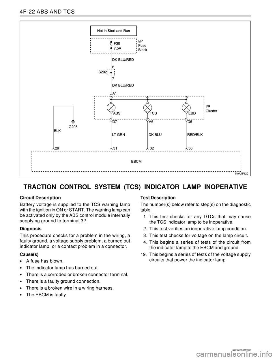
TRACTION CONTROL SYSTEM (TCS) INDICATOR LAMP INOPERATIVE
KAA4F120
Circuit Description
Battery voltage is supplied to the TCS warning lamp
with the ignition in ON or START. The warning lamp can
be activated only by the ABS control module internally
supplying ground to terminal 32.
Diagnosis
This procedure checks for a problem in the wiring, a
faulty ground, a voltage supply problem, a burned out
indicator lamp, or a contact problem in a connector.
Cause(s)
A fuse has blown.
The indicator lamp has burned out.
There is a corroded or broken connector terminal.
There is a faulty ground connection.
There is a broken wire in a wiring harness.
The EBCM is faulty.Test Description
The number(s) below refer to step(s) on the diagnostic
table.
1. This test checks for any DTCs that may cause
the TCS indicator lamp to be inoperative.
2. This test verifies an inoperative lamp condition.
3. This test checks for voltage on the lamp circuit.
4. This begins a series of tests of the circuit from
the indicator lamp to the EBCM and ground.
19. This begins a series of tests of the voltage supply
circuits that power the indicator lamp.
Page 1009 of 2053
SSANGYONG MY2002
4F-26 ABS AND TCS
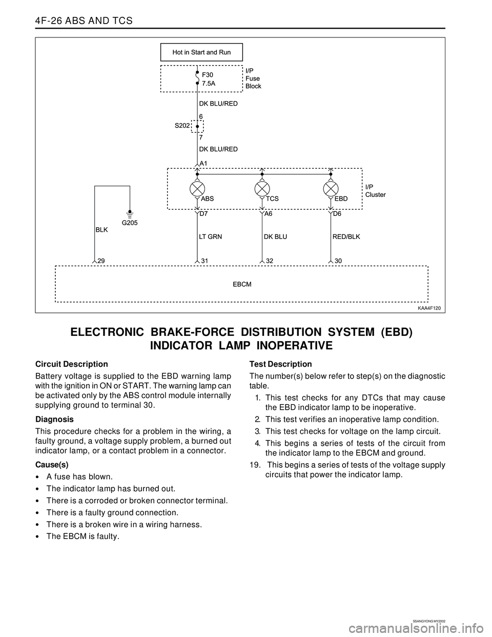
ELECTRONIC BRAKE-FORCE DISTRIBUTION SYSTEM (EBD)
INDICATOR LAMP INOPERATIVE
KAA4F120
Circuit Description
Battery voltage is supplied to the EBD warning lamp
with the ignition in ON or START. The warning lamp can
be activated only by the ABS control module internally
supplying ground to terminal 30.
Diagnosis
This procedure checks for a problem in the wiring, a
faulty ground, a voltage supply problem, a burned out
indicator lamp, or a contact problem in a connector.
Cause(s)
A fuse has blown.
The indicator lamp has burned out.
There is a corroded or broken connector terminal.
There is a faulty ground connection.
There is a broken wire in a wiring harness.
The EBCM is faulty.Test Description
The number(s) below refer to step(s) on the diagnostic
table.
1. This test checks for any DTCs that may cause
the EBD indicator lamp to be inoperative.
2. This test verifies an inoperative lamp condition.
3. This test checks for voltage on the lamp circuit.
4. This begins a series of tests of the circuit from
the indicator lamp to the EBCM and ground.
19. This begins a series of tests of the voltage supply
circuits that power the indicator lamp.
Page 1013 of 2053
SSANGYONG MY2002
4F-30 ABS AND TCS
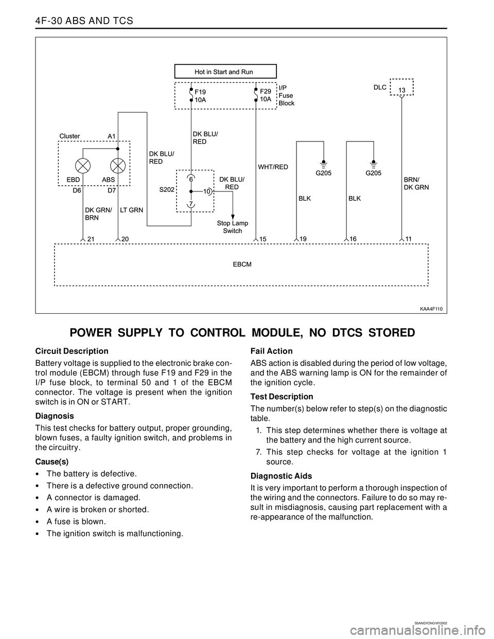
POWER SUPPLY TO CONTROL MODULE, NO DTCS STORED
KAA4F110
Circuit Description
Battery voltage is supplied to the electronic brake con-
trol module (EBCM) through fuse F19 and F29 in the
I/P fuse block, to terminal 50 and 1 of the EBCM
connector. The voltage is present when the ignition
switch is in ON or START.
Diagnosis
This test checks for battery output, proper grounding,
blown fuses, a faulty ignition switch, and problems in
the circuitry.
Cause(s)
The battery is defective.
There is a defective ground connection.
A connector is damaged.
A wire is broken or shorted.
A fuse is blown.
The ignition switch is malfunctioning.Fail Action
ABS action is disabled during the period of low voltage,
and the ABS warning lamp is ON for the remainder of
the ignition cycle.
Test Description
The number(s) below refer to step(s) on the diagnostic
table.
1. This step determines whether there is voltage at
the battery and the high current source.
7. This step checks for voltage at the ignition 1
source.
Diagnostic Aids
It is very important to perform a thorough inspection of
the wiring and the connectors. Failure to do so may re-
sult in misdiagnosis, causing part replacement with a
re-appearance of the malfunction.
Page 1017 of 2053
SSANGYONG MY2002
4F-34 ABS AND TCS
ABS INDICATOR LAMP ILLUMINATED CONTINUOUSLY,
NO DTCS STORED
KAA4F120
Circuit Description
Battery voltage is supplied to the ABS warning lamp
with the ignition in ON or START. The warning lamp
should be activated only by the ABS control module
internally supplying ground to terminal 31.
Diagnosis
This procedure checks for a short to ground in the
wiring or a defective electronic brake control module
(EBCM).Cause(s)
There is a short to ground in the circuit between the
cluster terminal D7 and the EBCM terminal 31.
The EBCM is faulty.
Page 1021 of 2053
SSANGYONG MY2002
4F-38 ABS AND TCS
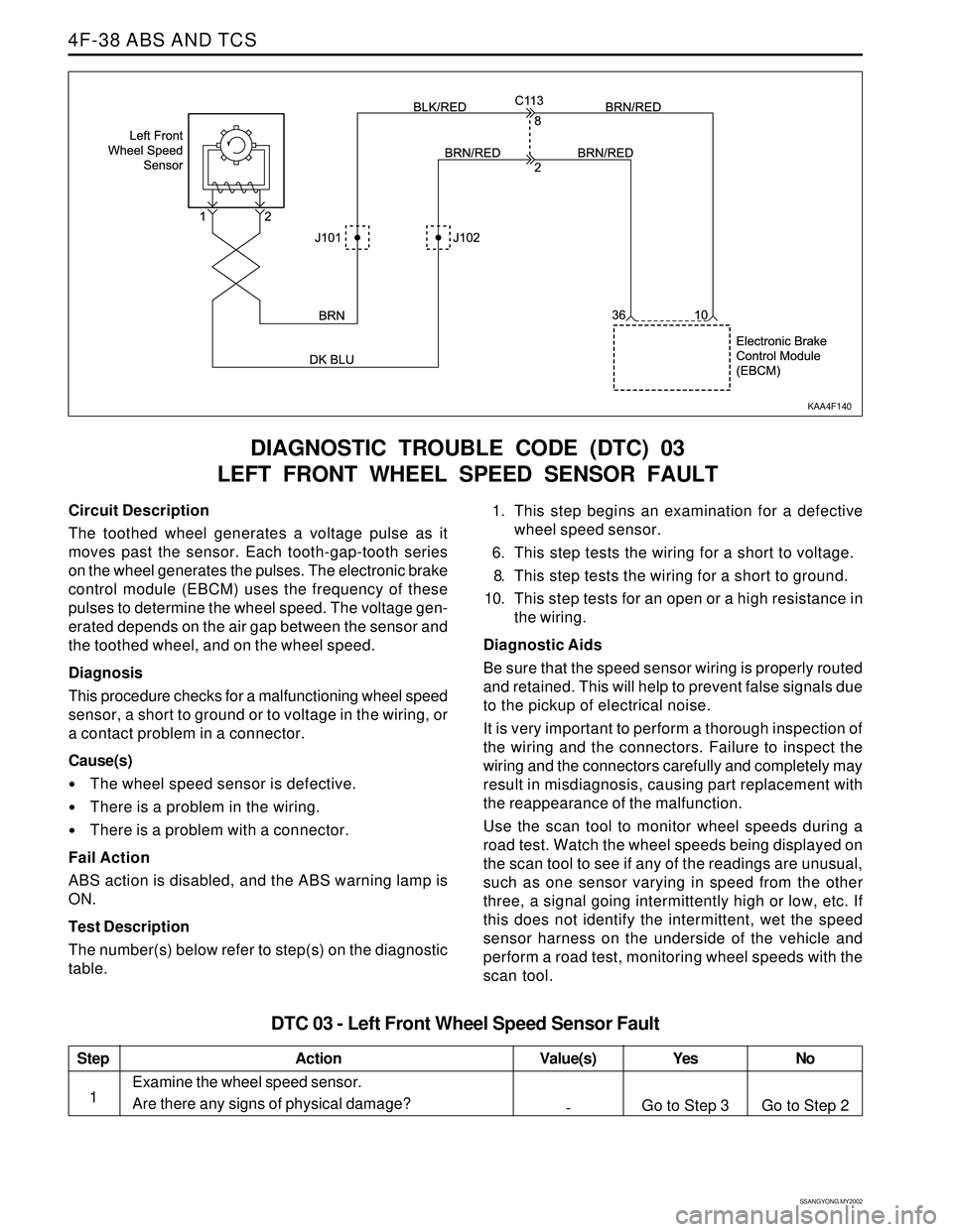
DIAGNOSTIC TROUBLE CODE (DTC) 03
LEFT FRONT WHEEL SPEED SENSOR FAULT
KAA4F140
Circuit Description
The toothed wheel generates a voltage pulse as it
moves past the sensor. Each tooth-gap-tooth series
on the wheel generates the pulses. The electronic brake
control module (EBCM) uses the frequency of these
pulses to determine the wheel speed. The voltage gen-
erated depends on the air gap between the sensor and
the toothed wheel, and on the wheel speed.
Diagnosis
This procedure checks for a malfunctioning wheel speed
sensor, a short to ground or to voltage in the wiring, or
a contact problem in a connector.
Cause(s)
The wheel speed sensor is defective.
There is a problem in the wiring.
There is a problem with a connector.
Fail Action
ABS action is disabled, and the ABS warning lamp is
ON.
Test Description
The number(s) below refer to step(s) on the diagnostic
table.1. This step begins an examination for a defective
wheel speed sensor.
6. This step tests the wiring for a short to voltage.
8. This step tests the wiring for a short to ground.
10. This step tests for an open or a high resistance in
the wiring.
Diagnostic Aids
Be sure that the speed sensor wiring is properly routed
and retained. This will help to prevent false signals due
to the pickup of electrical noise.
It is very important to perform a thorough inspection of
the wiring and the connectors. Failure to inspect the
wiring and the connectors carefully and completely may
result in misdiagnosis, causing part replacement with
the reappearance of the malfunction.
Use the scan tool to monitor wheel speeds during a
road test. Watch the wheel speeds being displayed on
the scan tool to see if any of the readings are unusual,
such as one sensor varying in speed from the other
three, a signal going intermittently high or low, etc. If
this does not identify the intermittent, wet the speed
sensor harness on the underside of the vehicle and
perform a road test, monitoring wheel speeds with the
scan tool.
Step
1
DTC 03 - Left Front Wheel Speed Sensor Fault
Action Yes
Go to Step 3No
Go to Step 2 Value(s)
-
Examine the wheel speed sensor.
Are there any signs of physical damage?