1997 SSANGYONG KORANDO transfer case
[x] Cancel search: transfer casePage 1099 of 2053
AUTOMATIC TRANSMISSION 5A-5
SSANGYONG MY2002
Engine Speed
The engine speed signal is derived from the Control-
ler Area Network (CAN) via Engine Control Module
(ECM).
Vehicle Speed
The vehicle speed sensor, which is located in the
transfer case, sends the output shaft speed signal
to the Engine Control Module (ECM). The information
is then transferred to the TCM via the CAN.
Transmission Fluid Temperature
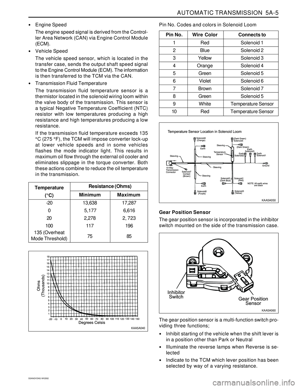
The transmission fluid temperature sensor is a
thermistor located in the solenoid wiring loom within
the valve body of the transmission. This sensor is
a typical Negative Temperature Coefficient (NTC)
resistor with low temperatures producing a high
resistance and high temperatures producing a low
resistance.
If the transmission fluid temperature exceeds 135
°C (275 °F), the TCM will impose converter lock-up
at lower vehicle speeds and in some vehicles
flashes the mode indicator light. This results in
maximum oil flow through the external oil cooler and
eliminates slippage in the torque converter. Both
these actions combine to reduce the oil temperature
in the transmission.
Minimum Temperature
(°C)Resistance (Ohms)
-20
0
20
100
135 (Overheat
Mode Threshold)13,638
5,177
2,278
117
75
Maximum
17,287
6,616
2, 723
196
85
Pin No. Wire ColorConnects to
1 Red Solenoid 1
2 BlueSolenoid 2
3 YellowSolenoid 3
4 OrangeSolenoid 4
5 GreenSolenoid 5
6 VioletSolenoid 6
7 BrownSolenoid 7
8 GreenSolenoid 5
9 White Temperature Sensor
10 Red Temperature Sensor
Pin No. Codes and colors in Solenoid Loom
KAA5A040KAA5A050
Gear Position Sensor
The gear position sensor is incorporated in the inhibitor
switch mounted on the side of the transmission case.
Inhibit starting of the vehicle when the shift lever is
in a position other than Park or Neutral
Illuminate the reverse lamps when Reverse is se-
lected
Indicate to the TCM which lever position has been
selected by way of a varying resistance. The gear position sensor is a multi-function switch pro-
viding three functions;
KAA5A060
Page 1245 of 2053
AUTOMATIC TRANSMISSION 5A-157
SSANGYONG MY2002
ON-VEHICLE SERVICE
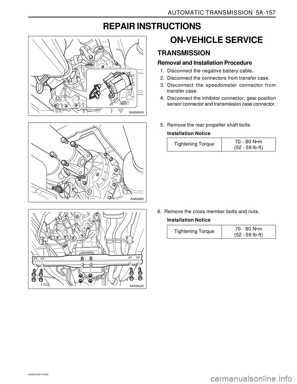
TRANSMISSION
Removal and Installation Procedure
1. Disconnect the negative battery cable.
2. Disconnect the connectors from transfer case.
3. Disconnect the speedometer connector from
transfer case.
4. Disconnect the inhibitor connector, gear position
sensor connector and transmission case connector.
REPAIR INSTRUCTIONS
5. Remove the rear propeller shaft bolts.
Installation Notice
6. Remove the cross member bolts and nuts.
Installation Notice
KAA5A2I0
Tightening Torque70 - 80 N•m
(52 - 59 lb-ft)
Tightening Torque70 - 80 Nm
(52 - 59 lb-ft)
KAA5A2H0
KAA5A2J0
Page 1246 of 2053
5A-158 AUTOMATIC TRANSMISSION
SSANGYONG MY2002
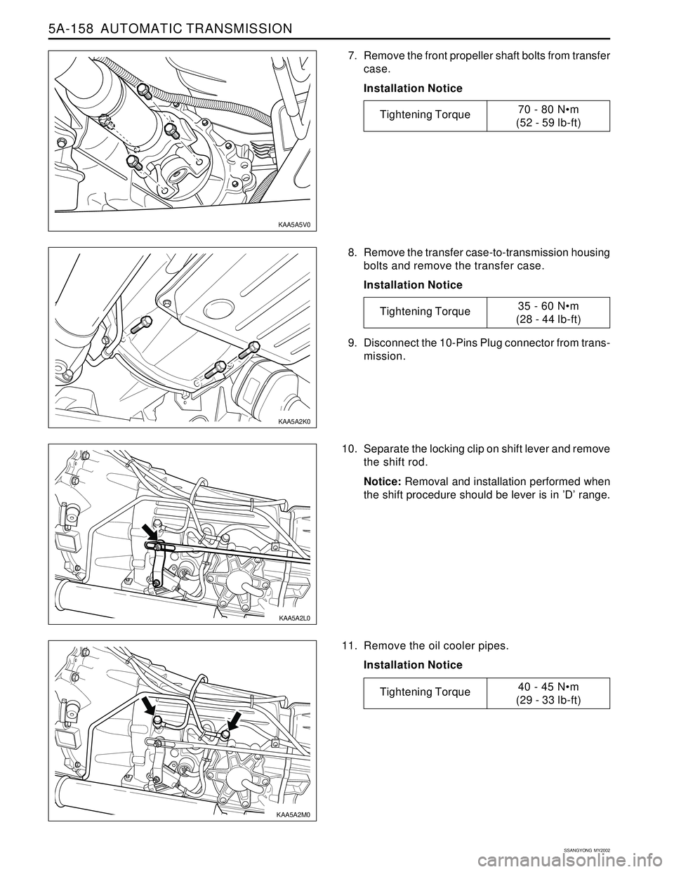
8. Remove the transfer case-to-transmission housing
bolts and remove the transfer case.
Installation Notice
10. Separate the locking clip on shift lever and remove
the shift rod.
Notice: Removal and installation performed when
the shift procedure should be lever is in ’D’ range.
11. Remove the oil cooler pipes.
Installation Notice 9. Disconnect the 10-Pins Plug connector from trans-
mission.
7. Remove the front propeller shaft bolts from transfer
case.
Installation Notice
KAA5A5V0
KAA5A2K0
KAA5A2L0
KAA5A2M0
Tightening Torque70 - 80 Nm
(52 - 59 lb-ft)
Tightening Torque35 - 60 Nm
(28 - 44 lb-ft)
Tightening Torque40 - 45 Nm
(29 - 33 lb-ft)
Page 1300 of 2053
AUTOMATIC TRANSMISSION 5A-205
SSANGYONG MY2002
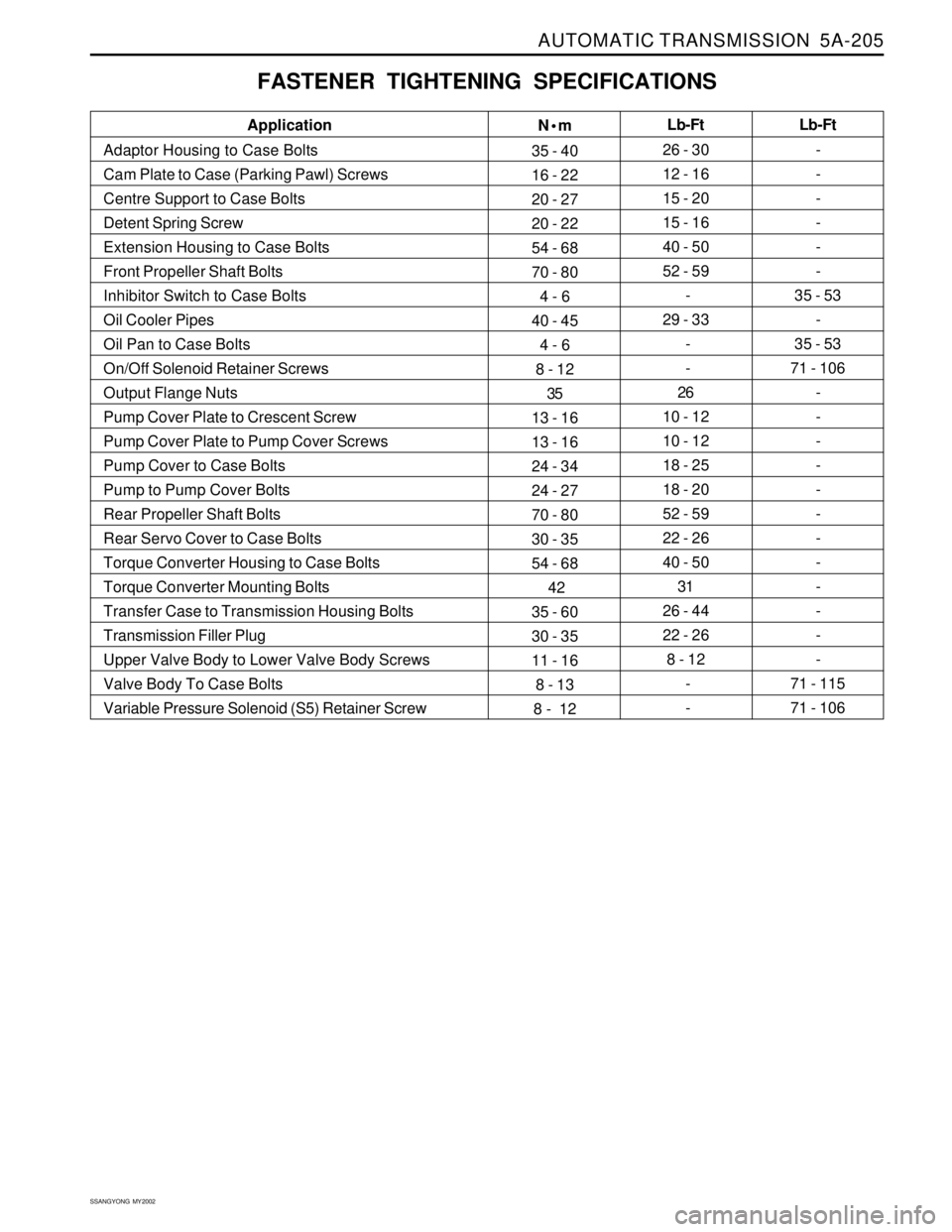
FASTENER TIGHTENING SPECIFICATIONS
N•m
35 - 40
16 - 22
20 - 27
20 - 22
54 - 68
70 - 80
4 - 6
40 - 45
4 - 6
8 - 12
35
13 - 16
13 - 16
24 - 34
24 - 27
70 - 80
30 - 35
54 - 68
42
35 - 60
30 - 35
11 - 16
8 - 13
8 - 12Lb-Ft
26 - 30
12 - 16
15 - 20
15 - 16
40 - 50
52 - 59
-
29 - 33
-
-
26
10 - 12
10 - 12
18 - 25
18 - 20
52 - 59
22 - 26
40 - 50
31
26 - 44
22 - 26
8 - 12
-
- Application
Adaptor Housing to Case Bolts
Cam Plate to Case (Parking Pawl) Screws
Centre Support to Case Bolts
Detent Spring Screw
Extension Housing to Case Bolts
Front Propeller Shaft Bolts
Inhibitor Switch to Case Bolts
Oil Cooler Pipes
Oil Pan to Case Bolts
On/Off Solenoid Retainer Screws
Output Flange Nuts
Pump Cover Plate to Crescent Screw
Pump Cover Plate to Pump Cover Screws
Pump Cover to Case Bolts
Pump to Pump Cover Bolts
Rear Propeller Shaft Bolts
Rear Servo Cover to Case Bolts
Torque Converter Housing to Case Bolts
Torque Converter Mounting Bolts
Transfer Case to Transmission Housing Bolts
Transmission Filler Plug
Upper Valve Body to Lower Valve Body Screws
Valve Body To Case Bolts
Variable Pressure Solenoid (S5) Retainer ScrewLb-Ft
-
-
-
-
-
-
35 - 53
-
35 - 53
71 - 106
-
-
-
-
-
-
-
-
-
-
-
-
71 - 115
71 - 106
Page 1318 of 2053
SSANGYONG MY2002
5B-10 MANUAL TRANSMISSION
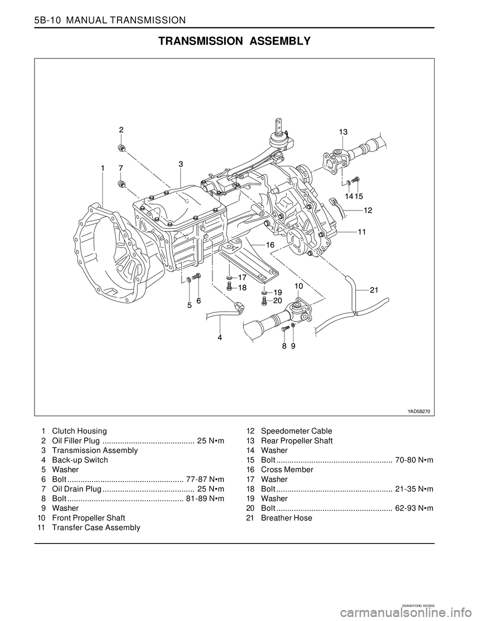
TRANSMISSION ASSEMBLY
YAD5B270
1 Clutch Housing
2 Oil Filler Plug.......................................... 25 N•m
3 Transmission Assembly
4 Back-up Switch
5 Washer
6 Bolt..................................................... 77-87 Nm
7 Oil Drain Plug.......................................... 25 Nm
8 Bolt..................................................... 81-89 Nm
9 Washer
10 Front Propeller Shaft
11 Transfer Case Assembly12 Speedometer Cable
13 Rear Propeller Shaft
14 Washer
15 Bolt..................................................... 70-80 Nm
16 Cross Member
17 Washer
18 Bolt..................................................... 21-35 Nm
19 Washer
20 Bolt..................................................... 62-93 Nm
21 Breather Hose
Page 1328 of 2053
SSANGYONG MY2002
5B-20 MANUAL TRANSMISSION
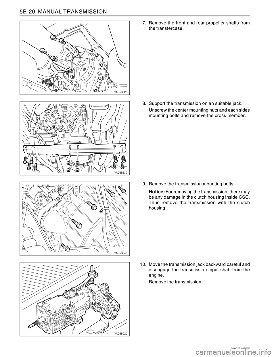
7. Remove the front and rear propeller shafts from
the transfercase.
8. Support the transmission on an suitable jack.
Unscrew the center mounting nuts and each sides
mounting bolts and remove the cross member.
9. Remove the transmission mounting bolts.
Notice: For removing the transmission, there may
be any damage in the clutch housing inside CSC.
Thus remove the transmission with the clutch
housing.
10. Move the transmission jack backward careful and
disengage the transmission input shaft from the
engine.
Remove the transmission.
YAD5B320
YAD5B330
YAD5B340
YAD5B020
Page 1372 of 2053
SECTION 5D1
TRANSFER CASE (TOD)
CAUTION: Disconnect the negative battery cable before removing or installing any electrical unit or when a
tool or equipment could easily come in contact with exposed electrical terminals. Disconnecting this cable
will help prevent personal injury and damage to the vehicle. The ignition must also be in LOCK unless
other-wise noted.
TABLE OF CONTENTS
Description and Operation.................................5D1-2
Torque on Demand (TOD) System
Transfer Case.................................................5D1-2
Transfer Case Control Unit (TCCU).....................5D1-2
TCCU Coding....................................................5D1-2
Pin Description..................................................5D1-3
Components of the TOD Transfer Case System ..5D1-4
Definition of Terminology....................................5D1-4
Operation of the TOD Transfer Case System......5D1-4
Component Locator...........................................5D1-7
Torque on Demand (TOD) Type Transfer Case....5D1-7
Transfer Case Disassembled View.....................5D1-8
TOD Control Unit..............................................5D1-10
Diagnosis..........................................................5D1-11
Self-Diagnostic Tests.......................................5D1-11
Diagnostic Trouble Codes (DTCs)....................5D1-12
Clearing Diagnostic Trouble Codes..................5D1-12
4WD Check Indicator Stays on with Ignition
Switch ON....................................................5D1-14
4WD Low Indicator Stays on with Ignition
Switch ON....................................................5D1-16
No 4WD Check or 4WD Low Indicator with
Ignition Switch ON........................................5D1-18
4WD Low Indicator Blink Steadily.....................5D1-20
TCCU Diagnostic System Check......................5D1-21
DTC 1714 Eeprom Checksum Fault..................5D1-22
DTC 1715 Tp Sensor Loss of Signal.................5D1-24
DTC 1716 Tp Sensor Out of Range...................5D1-26
DTC 1721 Electromagnetic Clutch Open / Short
to Battery.....................................................5D1-28
DTC 1722 Electromagnetic Clutch Short to
Ground.........................................................5D1-32
DTC 1731 Front Speed Sensor Voltage Low......5D1-36
DTC 1732 Front Speed Sensor Voltage High.....5D1-38DTC 1733 Rear Speed Sensor Voltage Low......5D1-40
DTC 1734 Rear Speed Sensor Voltage High.....5D1-42
DTC 1735 Speed Sensor Reference Voltage
Low ..............................................................5D1-44
DTC 1736 Speed Sensor Reference Voltage
High.............................................................5D1-46
DTC 1741 Motor Output Open / Shorted
to Battery.....................................................5D1-48
DTC 1742 Motor Output Shorted to Ground......5D1-52
DTC 1743 Shift System Timeout.......................5D1-55
DTC 1750 General Position Encoder Fault
(Invalid Code)...............................................5D1-56
DTC 1751 Position 1 Shorted to Ground............5D1-58
DTC 1752 Position 2 Shorted to Ground............5D1-60
DTC 1753 Position 3 Shorted to Ground............5D1-62
DTC 1754 Position 4 Shorted to Ground............5D1-64
Repair Instructions............................................5D1-66
On-Vehicle Service.............................................5D1-66
Oil Replacement..............................................5D1-66
Transfer Case Control Unit (TCCU)...................5D1-67
Transfer Case..................................................5D1-67
Shift Motor.......................................................5D1-69
Front and Rear Propeller Shaft Speed Sensor ...5D1-70
Unit Repair........................................................5D1-71
Transfer Case Overhaul...................................5D1-71
Specifications...................................................5D1-79
General Specification.......................................5D1-79
TCCU Electric Characteristics..........................5D1-79
Fastener Tightening Specifications...................5D1-79
Schematic and Routing Diagram....................5D1-80
TOD Transfer Case Control Unit (TCCU)............5D1-80
Special Tools and Equipment..........................5D1-82
Special Tool Table ...........................................5D1-82
Page 1373 of 2053
TRANSFER CASE 5D1-3
SSANGYONG MY2002
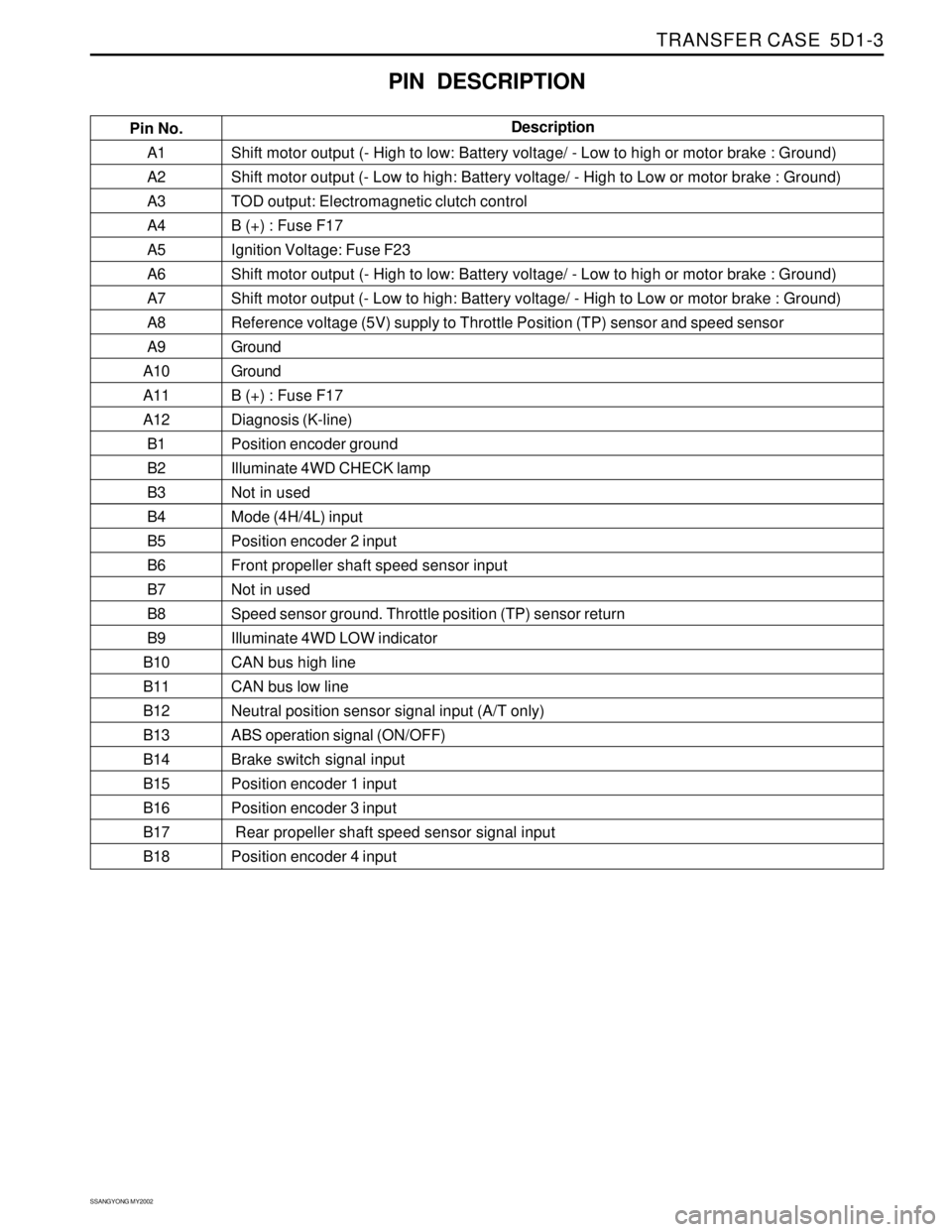
A1
A2
A3
A4
A5
A6
A7
A8
A9
A10
A11
A12
B1
B2
B3
B4
B5
B6
B7
B8
B9
B10
B11
B12
B13
B14
B15
B16
B17
B18Shift motor output (- High to low: Battery voltage/ - Low to high or motor brake : Ground)
Shift motor output (- Low to high: Battery voltage/ - High to Low or motor brake : Ground)
TOD output: Electromagnetic clutch control
B (+) : Fuse F17
Ignition Voltage: Fuse F23
Shift motor output (- High to low: Battery voltage/ - Low to high or motor brake : Ground)
Shift motor output (- Low to high: Battery voltage/ - High to Low or motor brake : Ground)
Reference voltage (5V) supply to Throttle Position (TP) sensor and speed sensor
Ground
Ground
B (+) : Fuse F17
Diagnosis (K-line)
Position encoder ground
Illuminate 4WD CHECK lamp
Not in used
Mode (4H/4L) input
Position encoder 2 input
Front propeller shaft speed sensor input
Not in used
Speed sensor ground. Throttle position (TP) sensor return
Illuminate 4WD LOW indicator
CAN bus high line
CAN bus low line
Neutral position sensor signal input (A/T only)
ABS operation signal (ON/OFF)
Brake switch signal input
Position encoder 1 input
Position encoder 3 input
Rear propeller shaft speed sensor signal input
Position encoder 4 input
PIN DESCRIPTION
Pin No.Description