1997 SSANGYONG KORANDO ip fuse block
[x] Cancel search: ip fuse blockPage 1064 of 2053
ABS AND TCS 4F-81
SSANGYONG MY2002
Step
1
2
3
4
5
6
7
8
9
10
11
12
13
14
15
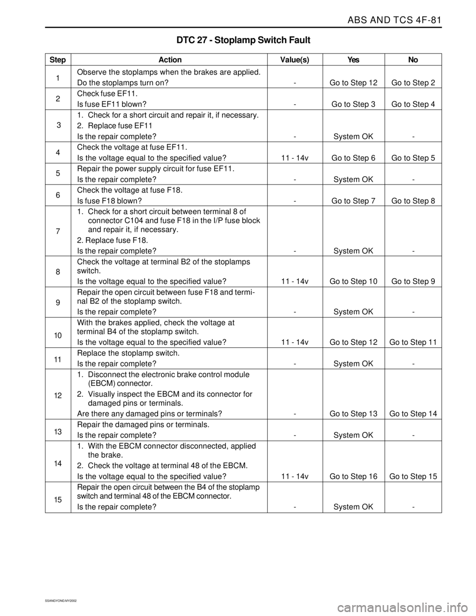
DTC 27 - Stoplamp Switch Fault
Action
Go to Step 12
Go to Step 3
System OK
Go to Step 6
System OK
Go to Step 7
System OK
Go to Step 10
System OK
Go to Step 12
System OK
Go to Step 13
System OK
Go to Step 16
System OKGo to Step 2
Go to Step 4
-
Go to Step 5
-
Go to Step 8
-
Go to Step 9
-
Go to Step 11
-
Go to Step 14
-
Go to Step 15
- -
-
-
11 - 14v
-
-
-
11 - 14v
-
11 - 14v
-
-
-
11 - 14v
-
Observe the stoplamps when the brakes are applied.
Do the stoplamps turn on?
Check fuse EF11.
Is fuse EF11 blown?
1. Check for a short circuit and repair it, if necessary.
2. Replace fuse EF11
Is the repair complete?
Check the voltage at fuse EF11.
Is the voltage equal to the specified value?
Repair the power supply circuit for fuse EF11.
Is the repair complete?
Check the voltage at fuse F18.
Is fuse F18 blown?
1. Check for a short circuit between terminal 8 of
connector C104 and fuse F18 in the I/P fuse block
and repair it, if necessary.
2. Replace fuse F18.
Is the repair complete?
Check the voltage at terminal B2 of the stoplamps
switch.
Is the voltage equal to the specified value?
Repair the open circuit between fuse F18 and termi-
nal B2 of the stoplamp switch.
Is the repair complete?
With the brakes applied, check the voltage at
terminal B4 of the stoplamp switch.
Is the voltage equal to the specified value?
Replace the stoplamp switch.
Is the repair complete?
1. Disconnect the electronic brake control module
(EBCM) connector.
2. Visually inspect the EBCM and its connector for
damaged pins or terminals.
Are there any damaged pins or terminals?
Repair the damaged pins or terminals.
Is the repair complete?
1. With the EBCM connector disconnected, applied
the brake.
2. Check the voltage at terminal 48 of the EBCM.
Is the voltage equal to the specified value?
Repair the open circuit between the B4 of the stoplamp
switch and terminal 48 of the EBCM connector.
Is the repair complete?
Value(s) Yes No
Page 1067 of 2053
SSANGYONG MY2002
4F-84 ABS AND TCS
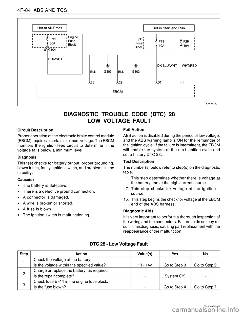
DIAGNOSTIC TROUBLE CODE (DTC) 28
LOW VOLTAGE FAULT
KAA4F240
Circuit Description
Proper operation of the electronic brake control module
(EBCM) requires a certain minimum voltage. The EBCM
monitors the ignition feed circuit to determine if the
voltage falls below a minimum level.
Diagnosis
This test checks for battery output, proper grounding,
blown fuses, faulty ignition switch, and problems in the
circuitry.
Cause(s)
The battery is defective.
There is a defective ground connection.
A connector is damaged.
A wire is broken or shorted.
A fuse is blown.
The ignition switch is malfunctioning.Fail Action
ABS action is disabled during the period of low voltage,
and the ABS warning lamp is ON for the remainder of
the ignition cycle. If the failure is intermittent, the EBCM
will enable the system at the next ignition cycle and
set a history DTC 28.
Test Description
The number(s) below refer to step(s) on the diagnostic
table.
1. This step determines whether there is voltage at
the battery and at the high current source.
7. This step checks for voltage at the ignition 1
source.
15. This step begins the check for voltage at the EBCM
end of the ABS harness.
Diagnostic Aids
It is very important to perform a thorough inspection of
the wiring and the connectors. Failure to do so may re-
sult in misdiagnosis, causing part replacement with the
reappearance of the malfunction.
Step
1
2
3
Action
Go to Step 3
System OK
Go to Step 4Go to Step 2
-
Go to Step 7 11 - 14v
-
-
Check the voltage at the battery.
Is the voltage within the specified value?
Charge or replace the battery, as required.
Is the repair complete?
Check fuse EF11 in the engine fuse block.
Is the fuse blown?
DTC 28 - Low Voltage Fault
Value(s) Yes No
Page 1068 of 2053
ABS AND TCS 4F-85
SSANGYONG MY2002
Step
4
5
6
7
8
9
10
11
12
13
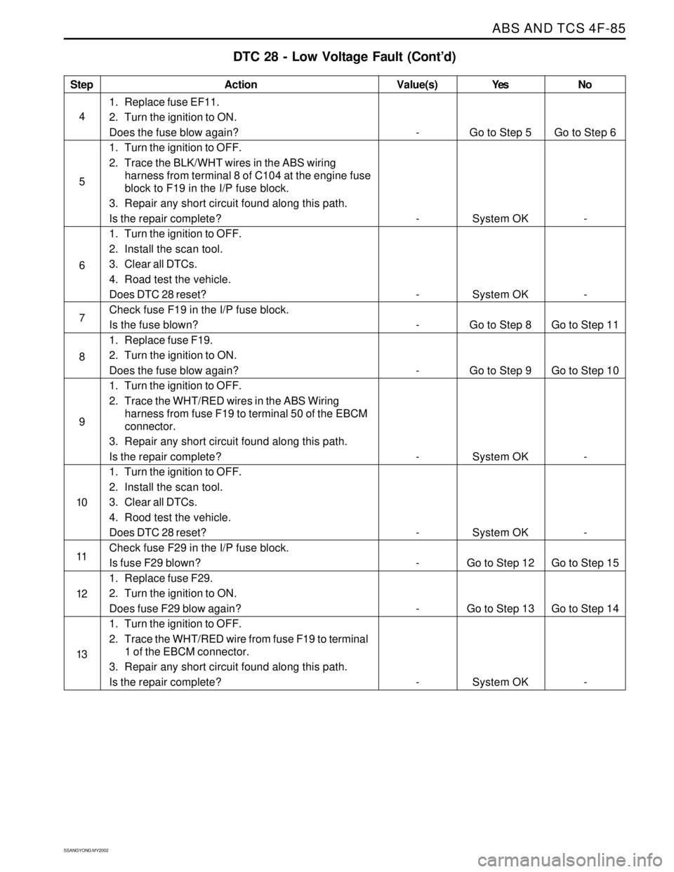
DTC 28 - Low Voltage Fault (Cont’d)
Action
Go to Step 5
System OK
System OK
Go to Step 8
Go to Step 9
System OK
System OK
Go to Step 12
Go to Step 13
System OKGo to Step 6
-
-
Go to Step 11
Go to Step 10
-
-
Go to Step 15
Go to Step 14
- -
-
-
-
-
-
-
-
-
-
1. Replace fuse EF11.
2. Turn the ignition to ON.
Does the fuse blow again?
1. Turn the ignition to OFF.
2. Trace the BLK/WHT wires in the ABS wiring
harness from terminal 8 of C104 at the engine fuse
block to F19 in the I/P fuse block.
3. Repair any short circuit found along this path.
Is the repair complete?
1. Turn the ignition to OFF.
2. Install the scan tool.
3. Clear all DTCs.
4. Road test the vehicle.
Does DTC 28 reset?
Check fuse F19 in the I/P fuse block.
Is the fuse blown?
1. Replace fuse F19.
2. Turn the ignition to ON.
Does the fuse blow again?
1. Turn the ignition to OFF.
2. Trace the WHT/RED wires in the ABS Wiring
harness from fuse F19 to terminal 50 of the EBCM
connector.
3. Repair any short circuit found along this path.
Is the repair complete?
1. Turn the ignition to OFF.
2. Install the scan tool.
3. Clear all DTCs.
4. Rood test the vehicle.
Does DTC 28 reset?
Check fuse F29 in the I/P fuse block.
Is fuse F29 blown?
1. Replace fuse F29.
2. Turn the ignition to ON.
Does fuse F29 blow again?
1. Turn the ignition to OFF.
2. Trace the WHT/RED wire from fuse F19 to terminal
1 of the EBCM connector.
3. Repair any short circuit found along this path.
Is the repair complete?
Value(s) Yes No
Page 1069 of 2053
SSANGYONG MY2002
4F-86 ABS AND TCS
Step
14
15
16
17
18
19
20
21
22
23
24
25
26
27
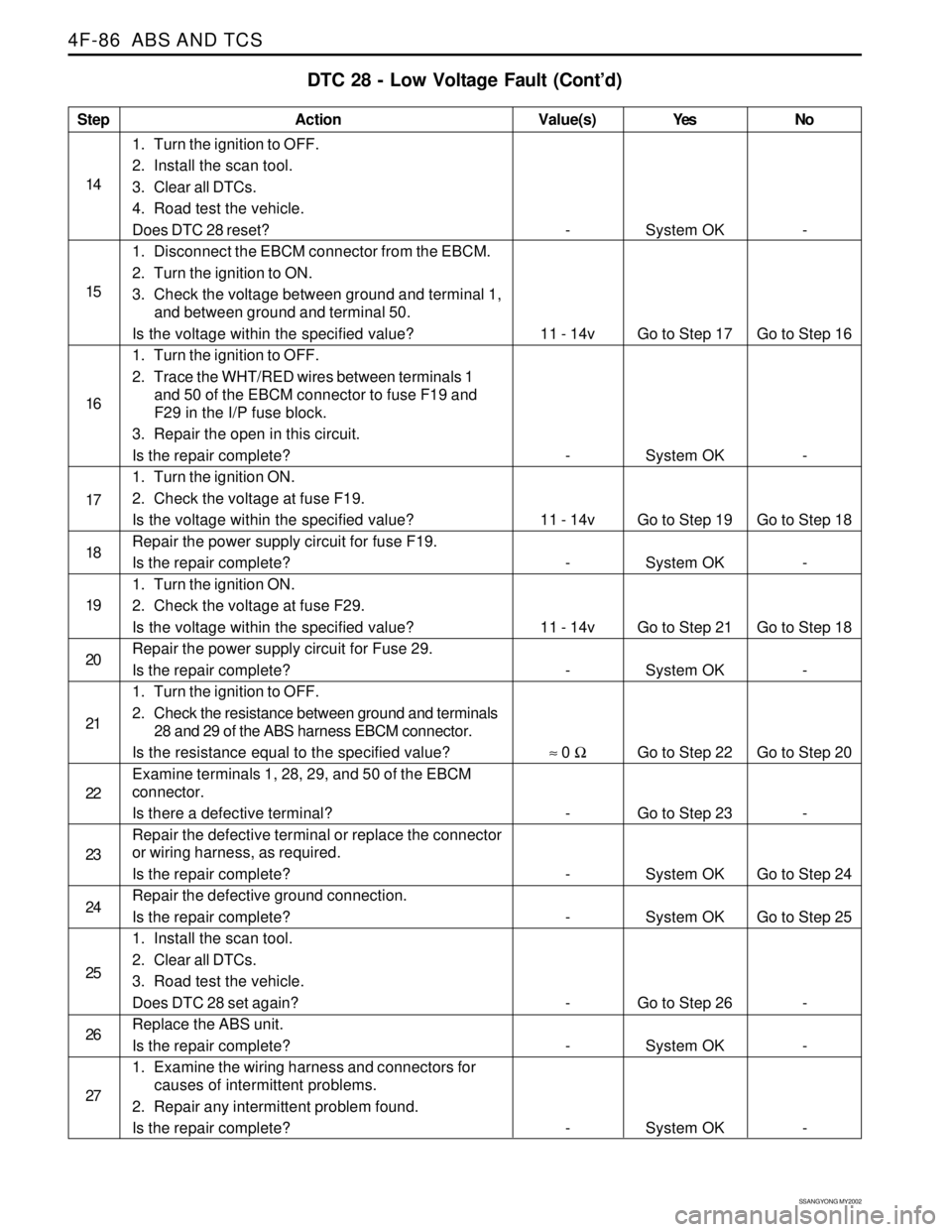
DTC 28 - Low Voltage Fault (Cont’d)
Action
System OK
Go to Step 17
System OK
Go to Step 19
System OK
Go to Step 21
System OK
Go to Step 22
Go to Step 23
System OK
System OK
Go to Step 26
System OK
System OK-
Go to Step 16
-
Go to Step 18
-
Go to Step 18
-
Go to Step 20
-
Go to Step 24
Go to Step 25
-
-
- -
11 - 14v
-
11 - 14v
-
11 - 14v
-
≈ 0 Ω
-
-
-
-
-
-
1. Turn the ignition to OFF.
2. Install the scan tool.
3. Clear all DTCs.
4. Road test the vehicle.
Does DTC 28 reset?
1. Disconnect the EBCM connector from the EBCM.
2. Turn the ignition to ON.
3. Check the voltage between ground and terminal 1,
and between ground and terminal 50.
Is the voltage within the specified value?
1. Turn the ignition to OFF.
2. Trace the WHT/RED wires between terminals 1
and 50 of the EBCM connector to fuse F19 and
F29 in the I/P fuse block.
3. Repair the open in this circuit.
Is the repair complete?
1. Turn the ignition ON.
2. Check the voltage at fuse F19.
Is the voltage within the specified value?
Repair the power supply circuit for fuse F19.
Is the repair complete?
1. Turn the ignition ON.
2. Check the voltage at fuse F29.
Is the voltage within the specified value?
Repair the power supply circuit for Fuse 29.
Is the repair complete?
1. Turn the ignition to OFF.
2. Check the resistance between ground and terminals
28 and 29 of the ABS harness EBCM connector.
Is the resistance equal to the specified value?
Examine terminals 1, 28, 29, and 50 of the EBCM
connector.
Is there a defective terminal?
Repair the defective terminal or replace the connector
or wiring harness, as required.
Is the repair complete?
Repair the defective ground connection.
Is the repair complete?
1. Install the scan tool.
2. Clear all DTCs.
3. Road test the vehicle.
Does DTC 28 set again?
Replace the ABS unit.
Is the repair complete?
1. Examine the wiring harness and connectors for
causes of intermittent problems.
2. Repair any intermittent problem found.
Is the repair complete?
Value(s) Yes No
Page 1085 of 2053
SSANGYONG MY2002
4F-102 ABS AND TCS
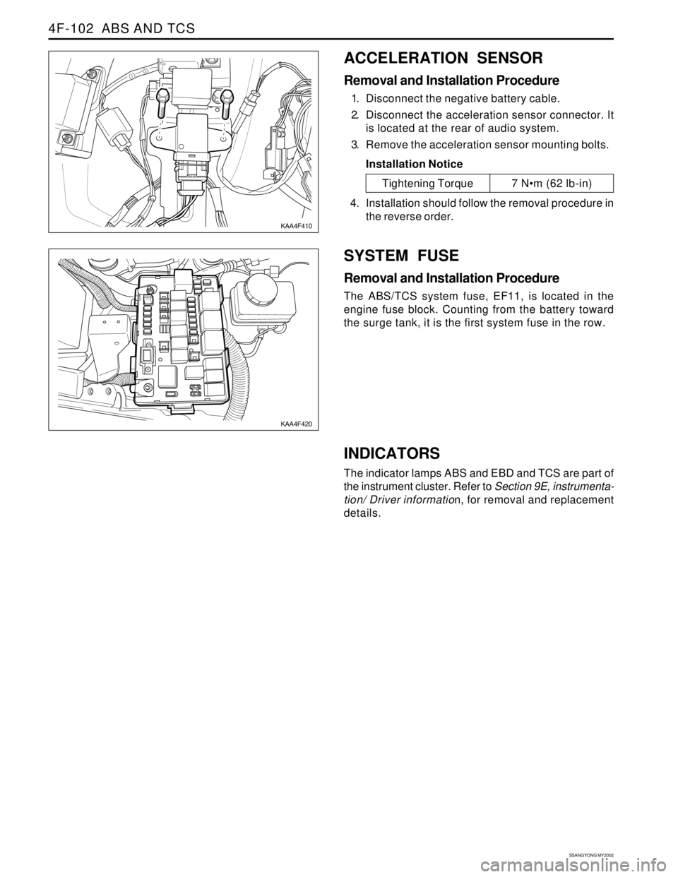
ACCELERATION SENSOR
Removal and Installation Procedure
1. Disconnect the negative battery cable.
2. Disconnect the acceleration sensor connector. It
is located at the rear of audio system.
3. Remove the acceleration sensor mounting bolts.
Installation Notice
SYSTEM FUSE
Removal and Installation Procedure
The ABS/TCS system fuse, EF11, is located in the
engine fuse block. Counting from the battery toward
the surge tank, it is the first system fuse in the row.
KAA4F410
KAA4F420
Tightening Torque 7 Nm (62 lb-in)
4. Installation should follow the removal procedure in
the reverse order.
INDICATORS
The indicator lamps ABS and EBD and TCS are part of
the instrument cluster. Refer to Section 9E, instrumenta-
tion/ Driver information, for removal and replacement
details.
Page 1509 of 2053
SSANGYONG MY2002
7A-8 HEATING AND VENTILATION SYSTEM
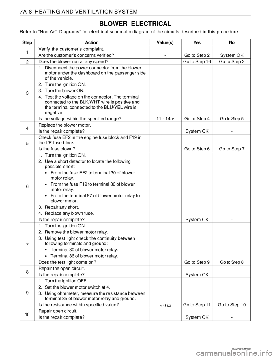
BLOWER ELECTRICAL
Refer to “Non A/C Diagrams” for electrical schematic diagram of the circuits described in this procedure.
Step
1
2
3
4
5
6
7
8
9
10
Action
Verify the customer’s complaint.
Are the customer’s concerns verified?
Does the blower run at any speed?
1. Disconnect the power connector from the blower
motor under the dashboard on the passenger side
of the vehicle.
2. Turn the ignition ON.
3. Turn the blower ON.
4. Test the voltage on the connector. The terminal
connected to the BLK/WHT wire is positive and
the terminal connected to the BLU/YEL wire is
negative.
Is the voltage within the specified range?
Replace the blower motor.
Is the repair complete?
Check fuse EF2 in the engine fuse block and F19 in
the I/P fuse block.
Is the fuse blown?
1. Turn the ignition ON.
2. Use a short detector to locate the following
possible short:
From the fuse EF2 to terminal 30 of blower
motor relay.
From the fuse F19 to terminal 86 of blower
motor relay.
From the terminal 87 of blower motor relay to
blower motor.
3. Repair any short.
4. Replace any blown fuse.
Is the repair complete?
1. Turn the ignition ON.
2. Remove the blower motor relay.
3. Using test light check the continuity between
following terminals and ground:
Terminal 30 of blower motor relay.
Terminal 86 of blower motor relay.
Does the test light come on?
Repair the open circuit.
Is the repair complete?
1. Turn the ignition OFF.
2. Set the blower motor switch at 4.
3. Using ohmmeter, measure the resistance between
terminal 85 of blower motor relay and ground.
Is the resistance within specified value?
Repair open circuit.
Is the repair complete?Yes
Go to Step 2
Go to Step 16
Go to Step 4
System OK
Go to Step 6
System OK
Go to Step 9
System OK
Go to Step 11
System OKNo
System OK
Go to Step 3
Go to Step 5
-
Go to Step 7
-
Go to Step 8
-
Go to Step 10
-
Value(s)
-
11 - 14 v
≈ 0 Ω
Page 1511 of 2053
SSANGYONG MY2002
7A-10 HEATING AND VENTILATION SYSTEM
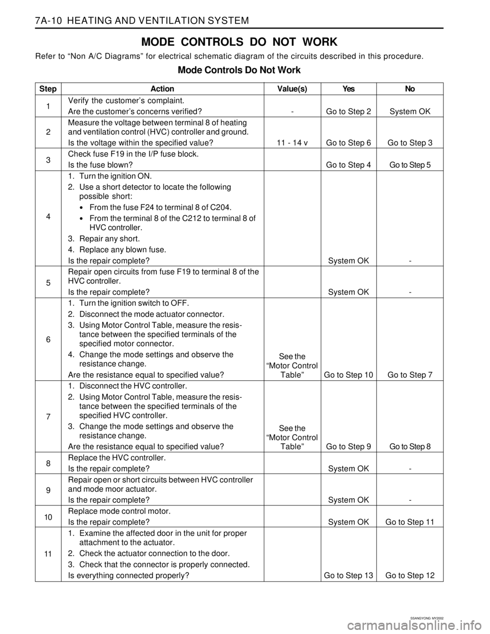
MODE CONTROLS DO NOT WORK
Refer to “Non A/C Diagrams” for electrical schematic diagram of the circuits described in this procedure.
Mode Controls Do Not Work
Step
1
2
3
4
5
6
7
8
9
10
11Action
Verify the customer’s complaint.
Are the customer’s concerns verified?
Measure the voltage between terminal 8 of heating
and ventilation control (HVC) controller and ground.
Is the voltage within the specified value?
Check fuse F19 in the I/P fuse block.
Is the fuse blown?
1. Turn the ignition ON.
2. Use a short detector to locate the following
possible short:
From the fuse F24 to terminal 8 of C204.
From the terminal 8 of the C212 to terminal 8 of
HVC controller.
3. Repair any short.
4. Replace any blown fuse.
Is the repair complete?
Repair open circuits from fuse F19 to terminal 8 of the
HVC controller.
Is the repair complete?
1. Turn the ignition switch to OFF.
2. Disconnect the mode actuator connector.
3. Using Motor Control Table, measure the resis-
tance between the specified terminals of the
specified motor connector.
4. Change the mode settings and observe the
resistance change.
Are the resistance equal to specified value?
1. Disconnect the HVC controller.
2. Using Motor Control Table, measure the resis-
tance between the specified terminals of the
specified HVC controller.
3. Change the mode settings and observe the
resistance change.
Are the resistance equal to specified value?
Replace the HVC controller.
Is the repair complete?
Repair open or short circuits between HVC controller
and mode moor actuator.
Is the repair complete?
Replace mode control motor.
Is the repair complete?
1. Examine the affected door in the unit for proper
attachment to the actuator.
2. Check the actuator connection to the door.
3. Check that the connector is properly connected.
Is everything connected properly?Yes
Go to Step 2
Go to Step 6
Go to Step 4
System OK
System OK
Go to Step 10
Go to Step 9
System OK
System OK
System OK
Go to Step 13No
System OK
Go to Step 3
Go to Step 5
-
-
Go to Step 7
Go to Step 8
-
-
Go to Step 11
Go to Step 12
Value(s)
-
11 - 14 v
See the
“Motor Control
Table”
See the
“Motor Control
Table”
Page 1513 of 2053
SSANGYONG MY2002
7A-12 HEATING AND VENTILATION SYSTEM
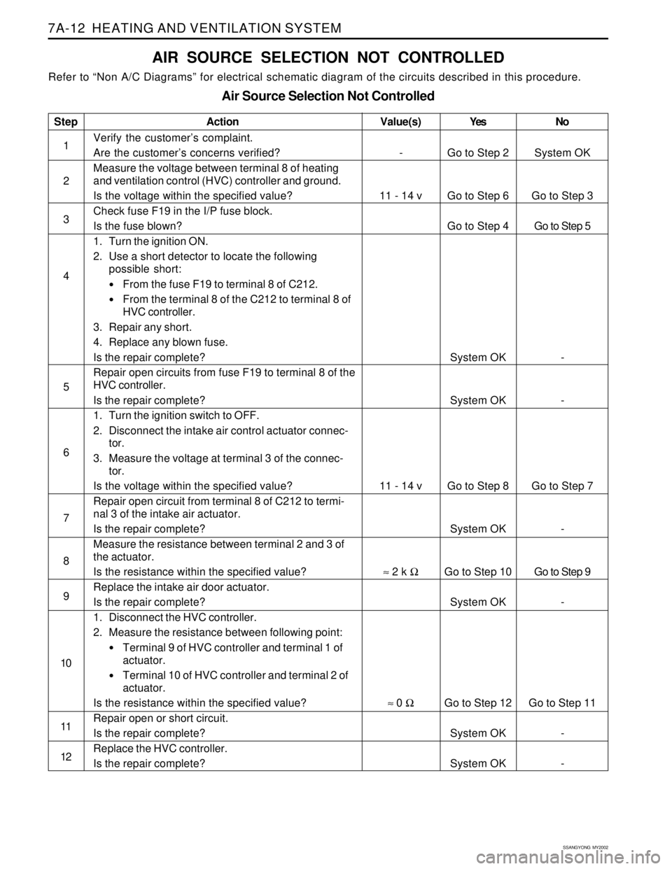
AIR SOURCE SELECTION NOT CONTROLLED
Refer to “Non A/C Diagrams” for electrical schematic diagram of the circuits described in this procedure.
Air Source Selection Not Controlled
Step
1
2
3
4
5
6
7
8
9
10
11
12Action
Verify the customer’s complaint.
Are the customer’s concerns verified?
Measure the voltage between terminal 8 of heating
and ventilation control (HVC) controller and ground.
Is the voltage within the specified value?
Check fuse F19 in the I/P fuse block.
Is the fuse blown?
1. Turn the ignition ON.
2. Use a short detector to locate the following
possible short:
From the fuse F19 to terminal 8 of C212.
From the terminal 8 of the C212 to terminal 8 of
HVC controller.
3. Repair any short.
4. Replace any blown fuse.
Is the repair complete?
Repair open circuits from fuse F19 to terminal 8 of the
HVC controller.
Is the repair complete?
1. Turn the ignition switch to OFF.
2. Disconnect the intake air control actuator connec-
tor.
3. Measure the voltage at terminal 3 of the connec-
tor.
Is the voltage within the specified value?
Repair open circuit from terminal 8 of C212 to termi-
nal 3 of the intake air actuator.
Is the repair complete?
Measure the resistance between terminal 2 and 3 of
the actuator.
Is the resistance within the specified value?
Replace the intake air door actuator.
Is the repair complete?
1. Disconnect the HVC controller.
2. Measure the resistance between following point:
Terminal 9 of HVC controller and terminal 1 of
actuator.
Terminal 10 of HVC controller and terminal 2 of
actuator.
Is the resistance within the specified value?
Repair open or short circuit.
Is the repair complete?
Replace the HVC controller.
Is the repair complete?Yes
Go to Step 2
Go to Step 6
Go to Step 4
System OK
System OK
Go to Step 8
System OK
Go to Step 10
System OK
Go to Step 12
System OK
System OKNo
System OK
Go to Step 3
Go to Step 5
-
-
Go to Step 7
-
Go to Step 9
-
Go to Step 11
-
-
Value(s)
-
11 - 14 v
11 - 14 v
≈ 2 k Ω
≈ 0 Ω