1997 SSANGYONG KORANDO glove box
[x] Cancel search: glove boxPage 1622 of 2053
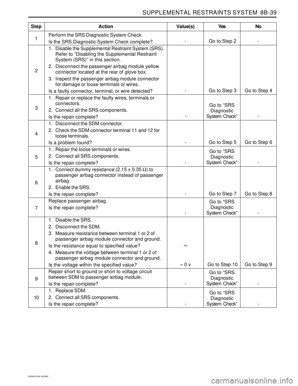
SUPPLEMENTAL RESTRAINTS SYSTEM 8B-39
SSANGYONG MY2002
Perform the SRS Diagnostic System Check.
Is the SRS Diagnostic System Check complete?
1. Disable the Supplemental Restraint System (SRS).
Refer to “Disabling the Supplemental Restraint
System (SRS)” in this section.
2. Disconnect the passenger airbag module yellow
connector located at the rear of glove box.
3. Inspect the passenger airbag module connector
for damage or loose terminals or wires.
Is a faulty connector, terminal, or wire detected?
1. Repair or replace the faulty wires, terminals or
connectors.
2. Connect all the SRS components.
Is the repair complete?
1. Disconnect the SDM connector.
2. Check the SDM connector terminal 11 and 12 for
loose terminals.
Is a problem found?
1. Repair the loose terminals or wires.
2. Connect all SRS components.
Is the repair complete?
1. Connect dummy resistance (2.15 ± 0.35 Ω) to
passenger airbag connector instead of passenger
airbag.
2. Enable the SRS.
Is the repair complete?
Replace passenger airbag.
Is the repair complete?
1. Disable the SRS.
2. Disconnect the SDM.
3. Measure resistance between terminal 1 or 2 of
passenger airbag module connector and ground.
Is the resistance equal to specified value?
4. Measure the voltage between terminal 1 or 2 of
passenger airbag module connector and ground.
Is the voltage within the specified value?
Repair short to ground or short to voltage circuit
between SDM to passenger airbag module.
Is the repair complete?
1. Replace SDM.
2. Connect all SRS components.
Is the repair complete?
StepAction Value(s) Yes No
2
4
5
6
- Go to Step 3 Go to Step 4
3
-Go to “SRS
Diagnostic
System Check” -
- Go to Step 5 Go to Step 6
-Go to “SRS
Diagnostic
System Check” -
-Go to “SRS
Diagnostic
System Check” - 7
8
9
10
-Go to “SRS
Diagnostic
System Check” - 1
- Go to Step 2 -
≈ 0 v Go to Step 10 Go to Step 9∞
- Go to Step 7 Go to Step 8
-Go to “SRS
Diagnostic
System Check” -
Page 1631 of 2053
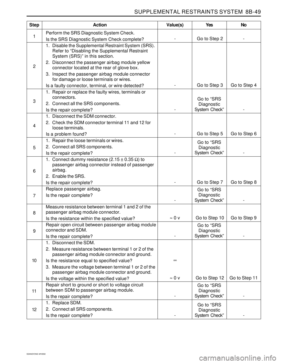
SUPPLEMENTAL RESTRAINTS SYSTEM 8B-49
SSANGYONG MY2002
Perform the SRS Diagnostic System Check.
Is the SRS Diagnostic System Check complete?
1. Disable the Supplemental Restraint System (SRS).
Refer to “Disabling the Supplemental Restraint
System (SRS)” in this section.
2. Disconnect the passenger airbag module yellow
connector located at the rear of glove box.
3. Inspect the passenger airbag module connector
for damage or loose terminals or wires.
Is a faulty connector, terminal, or wire detected?
1. Repair or replace the faulty wires, terminals or
connectors.
2. Connect all the SRS components.
Is the repair complete?
1. Disconnect the SDM connector.
2. Check the SDM connector terminal 11 and 12 for
loose terminals.
Is a problem found?
1. Repair the loose terminals or wires.
2. Connect all SRS components.
Is the repair complete?
1. Connect dummy resistance (2.15 ± 0.35 Ω) to
passenger airbag connector instead of passenger
airbag.
2. Enable the SRS.
Is the repair complete?
Replace passenger airbag.
Is the repair complete?
Measure resistance between terminal 1 and 2 of the
passenger airbag module connector.
Is the resistance within the specified value?
Repair open circuit between passenger airbag module
connector and SDM.
Is the repair complete?
1. Disconnect the SDM.
2. Measure resistance between terminal 1 or 2 of the
passenger airbag module connector and ground.
Is the resistance equal to specified value?
3. Measure the voltage between terminal 1 or 2 of the
passenger airbag module connector and ground.
Is the voltage within the specified value?
Repair short to ground or short to voltage circuit
between SDM to passenger airbag module.
Is the repair complete?
1. Replace SDM.
2. Connect all SRS components.
Is the repair complete?
StepAction Value(s) Yes No
2
4
5
6
- Go to Step 3 Go to Step 4
3
-Go to “SRS
Diagnostic
System Check” -
- Go to Step 5 Go to Step 6
-Go to “SRS
Diagnostic
System Check” -
7
8
9
10
-Go to “SRS
Diagnostic
System Check” - 1
- Go to Step 2 -
∞
- Go to Step 7 Go to Step 8
-Go to “SRS
Diagnostic
System Check” -
11
≈ 0 v Go to Step 10 Go to Step 9
≈ 0 v Go to Step 12 Go to Step 11
-Go to “SRS
Diagnostic
System Check” -
-Go to “SRS
Diagnostic
System Check” - 12
Page 1644 of 2053
SSANGYONG MY2002
8B-62 SUPPLEMENTAL RESTRAINTS SYSTEM
KAA8B160
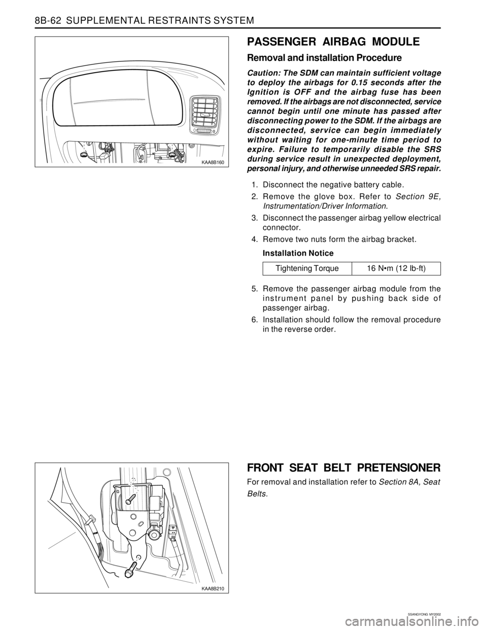
PASSENGER AIRBAG MODULE
Removal and installation Procedure
Caution: The SDM can maintain sufficient voltage
to deploy the airbags for 0.15 seconds after the
Ignition is OFF and the airbag fuse has been
removed. If the airbags are not disconnected, service
cannot begin until one minute has passed after
disconnecting power to the SDM. If the airbags are
disconnected, service can begin immediately
without waiting for one-minute time period to
expire. Failure to temporarily disable the SRS
during service result in unexpected deployment,
personal injury, and otherwise unneeded SRS repair.
1. Disconnect the negative battery cable.
2. Remove the glove box. Refer to Section 9E,
Instrumentation/Driver Information.
3. Disconnect the passenger airbag yellow electrical
connector.
4. Remove two nuts form the airbag bracket.
Installation Notice
5. Remove the passenger airbag module from the
instrument panel by pushing back side of
passenger airbag.
6. Installation should follow the removal procedure
in the reverse order.
Tightening Torque 16 Nm (12 lb-ft)
FRONT SEAT BELT PRETENSIONER
For removal and installation refer to Section 8A, Seat
Belts.
KAA8B210
Page 1718 of 2053

SECTION 9E
INSTRUMENTATION, DRIVER INFORMATION
CAUTION: Disconnect the negative battery cable before removing or installing any electrical unit or when a
tool or equipment could easily come in contact with exposed electrical terminals. Disconnecting this cable
will help prevent personal injury and damage to the vehicle. The ignition must also be in LOCK unless
otherwise noted.
TABLE OF CONTENTS
Description and Operation.................................. 9E-2
Cigar Lighter....................................................... 9E-2
Ashtray.............................................................. 9E-2
Instrument Panel Vents....................................... 9E-2
Glove Box.......................................................... 9E-2
Digital Clock....................................................... 9E-2
Instrument Cluster.............................................. 9E-2
Speedometer and Tachometer............................ 9E-2
Trip Odometer.................................................... 9E-2
Fuel Gauge......................................................... 9E-2
Temperature Gauge............................................ 9E-2
Instrument Cluster Indicator Lamps..................... 9E-2
Chime Module.................................................... 9E-2
Components Locator ........................................... 9E-3
Instrumentation/Driver Information....................... 9E-3
Diagnostic Information and Procedure.............. 9E-5
Cigar Lighter....................................................... 9E-5
Disital Clock....................................................... 9E-5
Speedo Meter..................................................... 9E-6
Fuel Gauge......................................................... 9E-7
Temperature Gauge............................................ 9E-8
Instrument Cluster Indicator Lamps..................... 9E-9
Repair Instructions............................................. 9E-10
On-Vehice Service Unit Repair............................. 9E-10
Center Tray....................................................... 9E-10
Center Facia..................................................... 9E-10
Ashtray............................................................ 9E-10
Cigar Lighter..................................................... 9E-11Cup Holder....................................................... 9E-11
Instrument Panel Vent....................................... 9E-11
Glove Box........................................................ 9E-12
Chime Module.................................................. 9E-12
Hood Latch Release Handle.............................. 9E-12
Instrument Lower Cover.................................... 9E-13
Instrument Cluster Trim Panel........................... 9E-13
Instrument Cluster............................................ 9E-13
Speedometer/Odometer/Trip Odometer/
Tachometer................................................... 9E-14
Fuel Gauge....................................................... 9E-14
Temperature Gauge .......................................... 9E-15
Digital Clock..................................................... 9E-15
Instrument Cluster Indicator Lamps................... 9E-15
Instrument Panel............................................... 9E-16
Specifications.................................................... 9E-18
Bulb Usage Chart............................................. 9E-18
Schematic and Routing Diagram..................... 9E-19
Instrument Panel Illumination............................ 9E-19
Cluster (VSS, Meter & Gauge): Diesel.................9E-20
Cluster (VSS, Meter & Gauge): Gasoline............ 9E-21
Warning Lamp, TCS Indicator........................... 9E-22
Indicator........................................................... 9E-23
Warning Lamp.................................................. 9E-24
Digital Clock, Warning Cluster Illumination......... 9E-25
Selector Lever Position Lamp............................ 9E-26
Page 1719 of 2053

SSANGYONG MY2002
9E-2 INSTRUMENTATION, DRIVER INFORMATION
DESCRIPTION AND OPERATION
CIGAR LIGHTER
The cigar lighter is located in the front portion of the
floor console. To use the lighter, push it in completely.
When the lighter is hot, it will release itsef from contact
with the heating element. The lighter and the heating
element can be damaged if the lighter does not fully
release itsef from the heating element.
ASHTRAY
The ashtray is located in the console. To access the
ashtray, pullit out of the ashtray housing. The ashtray
lamp will go on when the parking lamps or headlamps
are turned on.
INSTRUMENT PANEL VENTS
The center and the side vents in the instrument panel
can be adjusted up and down and from side to side.
The side vents can also be aimed toward the side
windows to defog them.
GLOVE BOX
The glove box can be opened by pulling upon the latch
handle.
DIGITAL CLOCK
The digital clock is located in the instrument cluster.
INSTRUMENT CLUSTER
The instrument cluster is located above the steering
column and in the instrument cluster trim panel. The
instrument cluster contains the instruments that
provide the driver with vehicle performance information.
The instrument cluster contains a speedometer, a
tachometer, an odometer, a trip odometer, a
temperature gauge, a fuel gauge, and several indicator
lamps. For replacement of the indicator lamp bulbs
contained in the instrument cluster, refer to “Instrument
Cluster Indicator Lamps Specifications” in the section.
SPEEDOMETER AND
TACHOMETER
The speedometer measures the speed of the vehicle
in km/h (with mph) or mph (with km/h). It consists of
an instrument cluster gauge connected to the vehicle
speed sensor on the transaxle output shaft. The
tachometer measures the engine’s speed in terms of
thousands of revolutions per minute. It consists of an
instrument cluster gauge connected to a sending unit
in the engine con-trol module. Do not operate the
engine in the red zone. Engine damage may occur.
TRIP ODOMETER
The trip odometer measures the distance the vehicle
has traveled since it was last reset. It consists of an
instrument cluster gauge connected to the sending unit
on the tasnsaxle output shaft. The trip oddometer can
be record the distance traveled from any starting point.
FUEL GAUGE
The fuel gauge consists of an instrument cluster gauge
connected to a sending unit in the fuel tank. The fuel
gauge indicates the quantity of fuel in the tank only
when the ignition is turned to ON or ACC. When the
ignition is turned to LOCK or START, the pointer may
come to rest at any position.
TEMPERATURE GAUGE
The temperature gauge consists of an instrument
cluster gauge connected to a temperature sensor that
is in con-tact with the circulating engine coolant. The
temperature gauge indicates the temperature of the
coolant. Prolonged driving or idling in very hot weather
may cause the pointer to move beyond the center of
the gauge. The engine is overheating if the pointer
moves into the red zone at the upper limit of the gauge.
INSTRUMENT CLUSTER
INDICATOR LAMPS
The instrument cluster contains indicator lamps that
indicatethe functioning of certain systems or the
existenceof potential problems with the operation of
the vehicle. The indicator lamps are replaceable. For
replacement of the indicator lamps contained in the
instrument cluster, refer to “instrument cluster indicator
lamps specifications” in this section.
CHIME MODULE
The chime module will sound to bring attention to one
or more of the following conditions:
The lights are on and the ignition not in ACC, ON,
or START.
The ignition key is in the ignition switch when the
driver’s side door is open.
The seat belt is unbuckled when the ignition is in
ACC, ON, or START.
Voltage is supplied at all times through the fuse block
to power the chime module.
Page 1721 of 2053
SSANGYONG MY2002
9E-4 INSTRUMENTATION, DRIVER INFORMATION
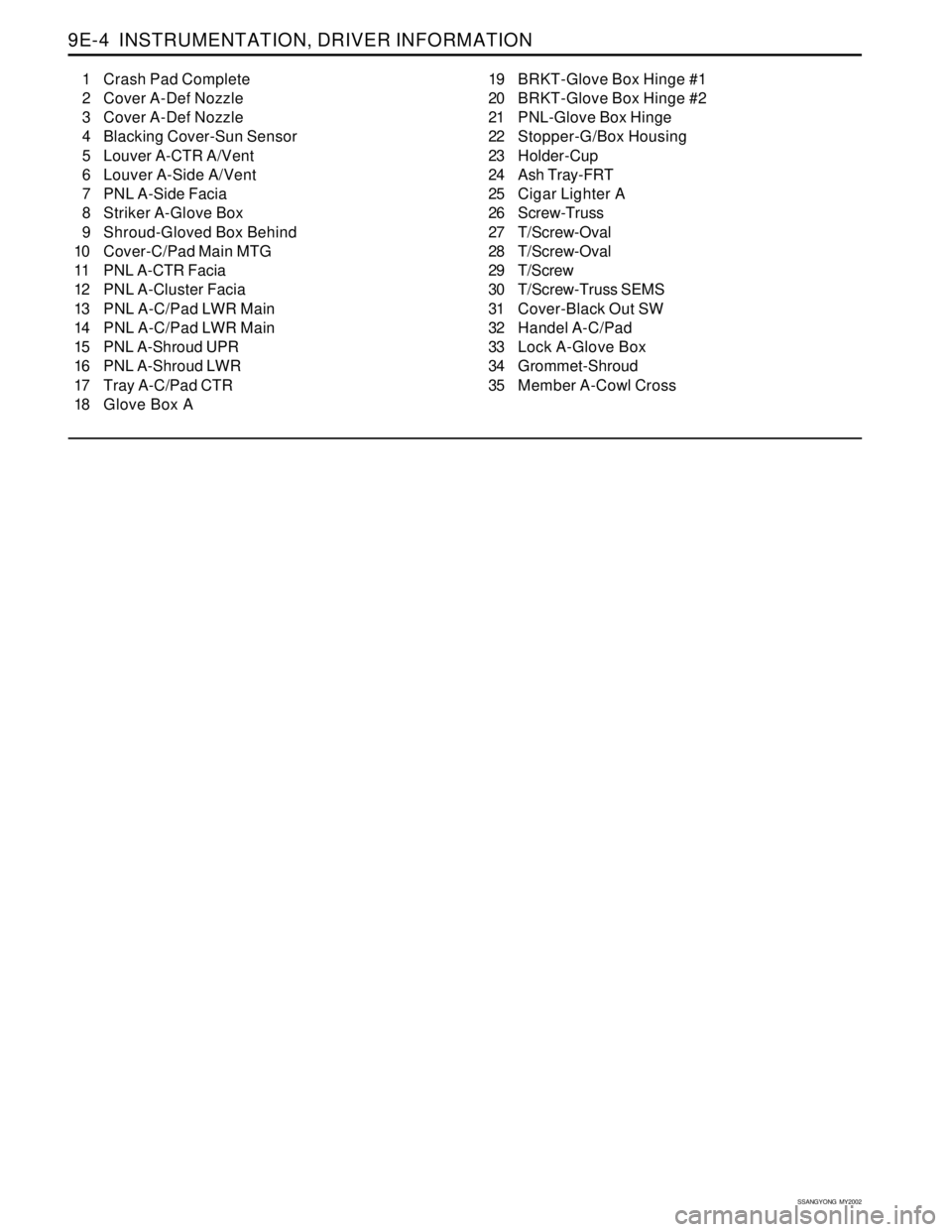
1 Crash Pad Complete
2 Cover A-Def Nozzle
3 Cover A-Def Nozzle
4 Blacking Cover-Sun Sensor
5 Louver A-CTR A/Vent
6 Louver A-Side A/Vent
7 PNL A-Side Facia
8 Striker A-Glove Box
9 Shroud-Gloved Box Behind
10 Cover-C/Pad Main MTG
11 PNL A-CTR Facia
12 PNL A-Cluster Facia
13 PNL A-C/Pad LWR Main
14 PNL A-C/Pad LWR Main
15 PNL A-Shroud UPR
16 PNL A-Shroud LWR
17 Tray A-C/Pad CTR
18 Glove Box A19 BRKT-Glove Box Hinge #1
20 BRKT-Glove Box Hinge #2
21 PNL-Glove Box Hinge
22 Stopper-G/Box Housing
23 Holder-Cup
24 Ash Tray-FRT
25 Cigar Lighter A
26 Screw-Truss
27 T/Screw-Oval
28 T/Screw-Oval
29 T/Screw
30 T/Screw-Truss SEMS
31 Cover-Black Out SW
32 Handel A-C/Pad
33 Lock A-Glove Box
34 Grommet-Shroud
35 Member A-Cowl Cross
Page 1729 of 2053
SSANGYONG MY2002
9E-12 INSTRUMENTATION, DRIVER INFORMATION
KAA9E090
KAA9E100
KAA9E110
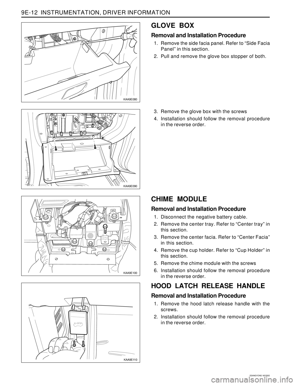
3. Remove the glove box with the screws
4. Installation should follow the removal procedure
in the reverse order.
HOOD LATCH RELEASE HANDLE
Removal and Installation Procedure
1. Remove the hood latch release handle with the
screws.
2. Installation should follow the removal procedure
in the reverse order.
KAA9E080
GLOVE BOX
Removal and Installation Procedure
1. Remove the side facia panel. Refer to “Side Facia
Panel” in this section.
2. Pull and remove the glove box stopper of both.
CHIME MODULE
Removal and Installation Procedure
1. Disconnect the negative battery cable.
2. Remove the center tray. Refer to “Center tray” in
this section.
3. Remove the center facia. Refer to “Center Facia”
in this section.
4. Remove the cup holder. Refer to “Cup Holder” in
this section.
5. Remove the chime module with the screws
6. Installation should follow the removal procedure
in the reverse order.
Page 1733 of 2053
SSANGYONG MY2002
9E-16 INSTRUMENTATION, DRIVER INFORMATION
KAA9E250
KAA9E250
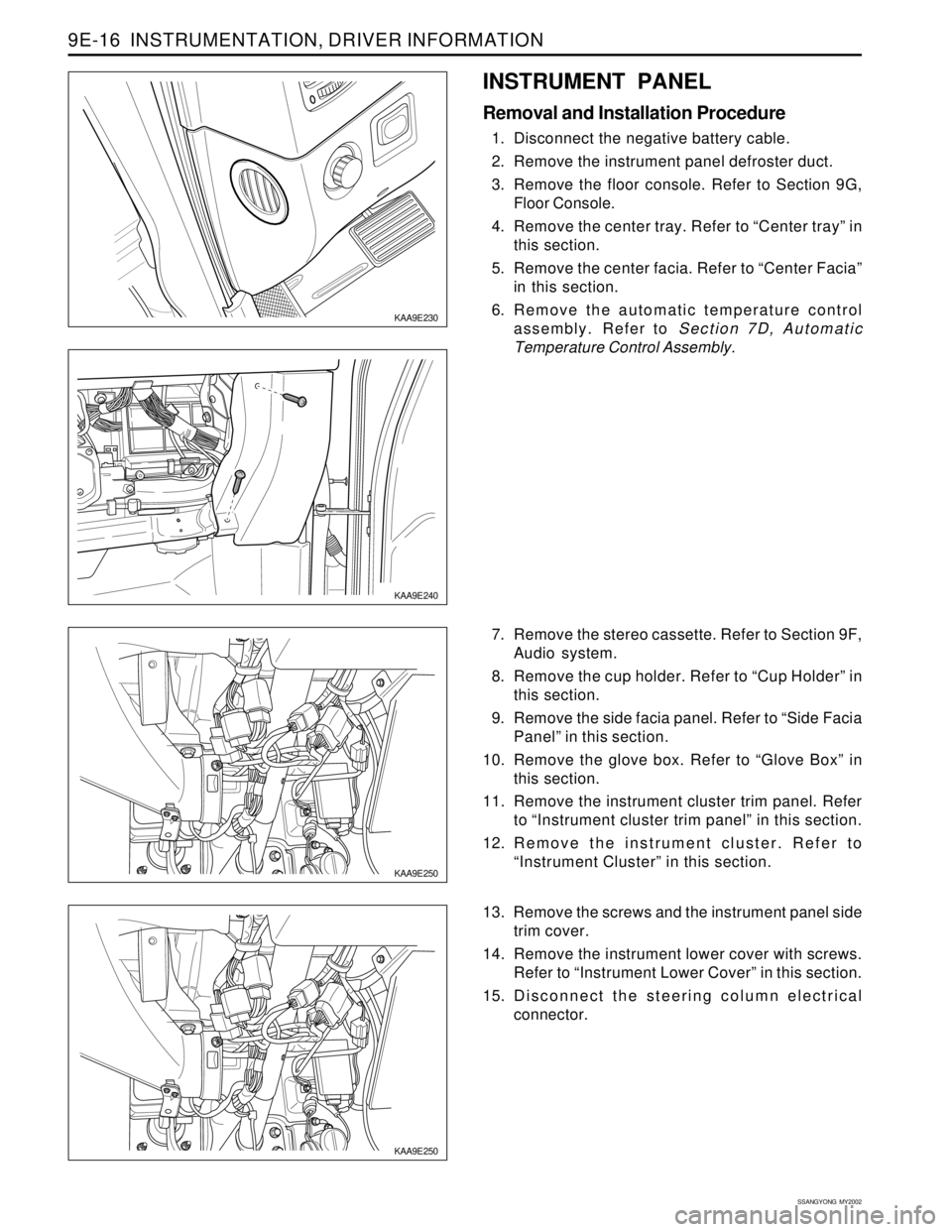
7. Remove the stereo cassette. Refer to Section 9F,
Audio system.
8. Remove the cup holder. Refer to “Cup Holder” in
this section.
9. Remove the side facia panel. Refer to “Side Facia
Panel” in this section.
10. Remove the glove box. Refer to “Glove Box” in
this section.
11. Remove the instrument cluster trim panel. Refer
to “Instrument cluster trim panel” in this section.
12. Remove the instrument cluster. Refer to
“Instrument Cluster” in this section.
13. Remove the screws and the instrument panel side
trim cover.
14. Remove the instrument lower cover with screws.
Refer to “Instrument Lower Cover” in this section.
15. Disconnect the steering column electrical
connector.
KAA9E240
INSTRUMENT PANEL
Removal and Installation Procedure
1. Disconnect the negative battery cable.
2. Remove the instrument panel defroster duct.
3. Remove the floor console. Refer to Section 9G,
Floor Console.
4. Remove the center tray. Refer to “Center tray” in
this section.
5. Remove the center facia. Refer to “Center Facia”
in this section.
6. Remove the automatic temperature control
assembly. Refer to Section 7D, Automatic
Temperature Control Assembly.
KAA9E230