1997 SSANGYONG KORANDO coolant level
[x] Cancel search: coolant levelPage 458 of 2053

1F2 -- 40 M161 ENGINE CONTROLS
D AEW OO M Y_2000
FUEL SYSTEM
The function of the fuel metering system is to deliver the correct amount of fuel to the engine under all operating condi-
tions. The fuel is delivered to the engine by the individual fuel injectors mounted into the intake manifold near each
cylinder.
The main fuel control sensors are the Mass Air Flow (MAF) sensor and the oxygen (O2) sensors.
The MAF sensor monitors the mass flow of the air being drawn into the engine. An electrically heated element is
mounted in the intake air stream, where it is cooled by the flow of incoming air. Engine Control Module (ECM) modu-
lates the flow of heating current to maintain the temperature differential between the heated film and the intake air at a
constant level. The amount of heating current required to maintain the temperature thus provides an index for the
mass air flow. This concept automatically compensates for variations in air density, as this is one of the factors that
determines the amount of warmth that the surrounding air absorbs from the heated element. MAF sensor is located
between the air filter and the throttle valve.
Under high fuel demands, the MAF sensor reads a high mass flow condition, such as wide open throttle. The ECM
uses this information to enrich the mixture, thus increasing the fuel injector on-- time, to provide the correct amount of
fuel. When decelerating, the mass flow decreases. This mass flow change is sensed by the MAF sensor and read by
the ECM, which then decreases the fuel injector on-- time due to the low fuel demand conditions.
The O2 sensors are located in the exhaust pipe before catalytic converter. The O2 sensors indicate to the ECM the
amount of oxygen in the exhaust gas, and the ECM changes the air/fuel ratio to the engine by controlling the fuel
injectors. The best air/fuel ratio to minimize exhaust emissions is 14.7 to 1, which allows the catalytic converter to
operate most efficiently. Because of the constant measuring and adjusting of the air/fuel ratio, the fuel injection system
is called a “closed loop” system.
The ECM uses voltage inputs from several sensors to determine how much fuel to provide to the engine. The fuel is
delivered under one of several conditions, called ‘‘modes”.
Starting Mode
When the ignition is turned ON, the ECM turns the fuel pump relay on for 1 second. The fuel pump then builds fuel
pressure. The ECM also checks the Engine Coolant Temperature (ECT) sensor and the Throttle Position (TP) sensor
and determines the proper air/fuel ratio for starting the engine. This ranges from 1.5 to 1 at -- 36°C(--33°F) coolant
temperature to 14.7 to 1 at 94°C (201°F) coolant temperature. The ECM controls the amount of fuel delivered in the
starting mode by changing how long the fuel injector is turned on and off. This is done by ‘‘pulsing” the fuel injectors for
very short times.
Run Mode
The run mode has two conditions called ‘‘open loop” and ‘‘closed loop”.
Open Loop
When the engine is first started and it is above 690 rpm, thesystem goes into “open loop” operation. In “open loop”, the
ECM ignores the signal from the HO2S and calculates the air/fuel ratio based on inputs from the ECT sensor and the
MAF sensor. The ECM stays in “open loop” until the following conditions are met:
DThe O2 has a varying voltage output, showing that it is hot enough to operate properly.
DThe ECT sensor is above a specified temperature (22.5°C).
DA specific amount of time has elapsed after starting the engine.
Closed Loop
The specific values for the above conditions vary with different engines and are stored in the Electronically Erasable
Programmable Read -- Only Memory (EEPROM). When these conditions are met, thesystem goes into “closed loop”
operation. In “closed loop”, the ECM calculates the air/fuel ratio (fuel injector on-- time) based on the signals from the
O2 sensors. This allows the air/fuel ratio to stay very close to 14.7 to 1.
Acceleration Mode
The ECM responds to rapid changes in throttle position and airflow and provides extra fuel.
Deceleration Mode
The ECM responds to changes in throttle position and airflow and reduces the amount of fuel. When deceleration is
very fast, the ECM can cut off fuel completely for short periods of time.
Page 549 of 2053
1A3 -- 14 GENERAL ENGINE INFORMATION
D AEW OO M Y_2000
Leakage Test
1. Run the engine to be the coolant temperature 80_C.
2. Remove the fuel injection nozzle.
3. Open the coolant subtank cap.
4. Check the coolant level and replenish if necessary.
5. Open the oil filler cap.
6. Remove the air cleaner cover and element.
7. Position the piston at TDC.
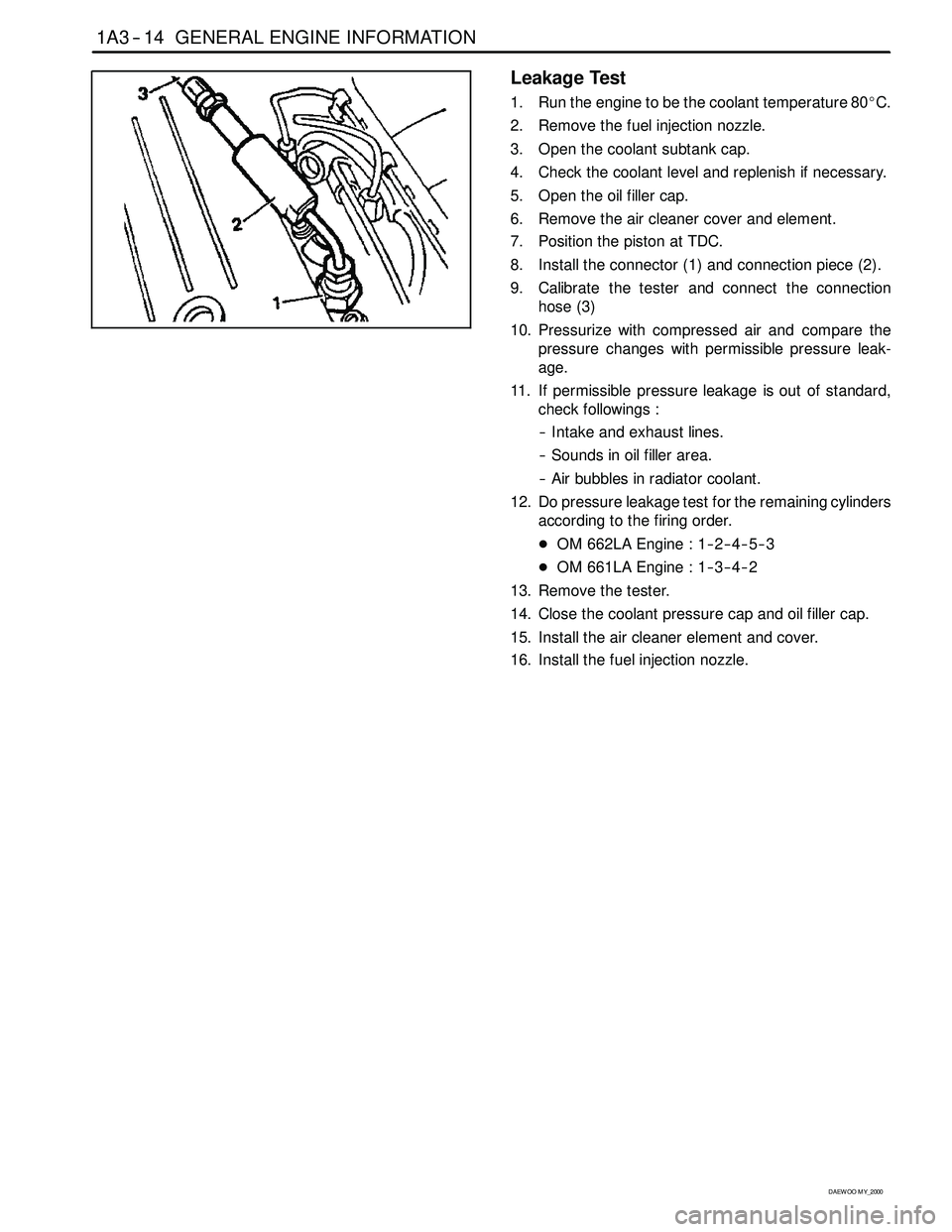
8. Install the connector (1) and connection piece (2).
9. Calibrate the tester and connect the connection
hose (3)
10. Pressurize with compressed air and compare the
pressure changes with permissible pressure leak-
age.
11. If permissible pressure leakage is out of standard,
check followings :
-- Intake and exhaust lines.
-- Sounds in oil filler area.
-- Air bubbles in radiator coolant.
12. Do pressure leakage test for the remaining cylinders
according to the firing order.
DOM 662LA Engine : 1-- 2-- 4-- 5-- 3
DOM 661LA Engine : 1-- 3-- 4-- 2
13. Remove the tester.
14. Close the coolant pressure cap and oil filler cap.
15. Install the air cleaner element and cover.
16. Install the fuel injection nozzle.
Page 740 of 2053

OM600 ENGINE COOLING 1D3 -- 5
D AEW OO M Y_2000
MAINTENANCE AND REPAIR
ON -- VEHICLE SERVICE
DRAIN AND FILLING OF COOLANT
Preceding Work : Removal of skid plate
Drain / Filling
1. Loosen the pressure cap of reservoir by 1 notch and
remove pressure and then loosen the cap.
Notice
Do not remove radiator cap when coolant is above
90°C.
2. Open the drain plug and drain the coolant.
Notice
Collect the coolant by using the proper bottle.
3. Remove the drain plug(1) and seal(2) of cylinder
block and drain the coolant.
4. Replace the seal to new one and tighten the drain
plug.
Installation Notice
Tightening Torque30 N∙m (22 lb-ft)
5. Tighten the drain plug of the lower radiator.
6. Fill the coolant through coolant reservoir -- tank.
Notice
DA proportion of 50% by volume of water / anticor-
rosion must be ensured.
7. After engine is running at idle speed, check the level
of coolant. If necessary, add enough specified cool-
ant.
Page 1134 of 2053
5A-40 AUTOMATIC TRANSMISSION
SSANGYONG MY2002
Dye and Black Light Method
1. Add dye to the transmission through the transmission
fluid filler plug. Follow the manufacturer’s recommen-
dation for the amount of dye to be used.
2. Use the black light to find the fluid leak.
3. Make the necessary repairs.
Repairing the Fluid Leak
Once the leak point is found the source of the leak
must be determined. The following list describes the
potential causes for the leak:
Fasteners are not torqued to specification.
Fastener threads and fastener holes are dirty or
corroded.
Gaskets, seals or sleeves are misaligned, damaged
or worn.
Damaged, warped or scratched seal bore or gasket
surface.
Loose or worn bearing causing excess seal or sleeve
wear.
Case or component porosity.
Fluid level is too high.
Plugged vent or damaged vent tube.
Water or coolant in fluid.
Fluid drain back holes plugged.
ELECTRICAL / GARAGE SHIFT
TEST
This preliminary test should be performed before a hoist
or road test to make sure electronic control inputs are
connected and operating. If the inputs are not checked
before operating the transmission, a simple electrical
condition could be misdiagnosed as a major
transmission condition.
A scan tool provides valuable information and must
be used on the automatic transmission for accurate
diagnosis.
1. Move gear shift control lever to P (Park) and set
the parking brake.
2. Connect scan tool to Data Link Connector (DLC)
terminal.
3. Start engine.
4. Turn the scan tool ON.
5. Verify that the appropriate signals are present.
These signals may include:
ENGINE SPEED
VEHICLE SPEED
THROTTLE POSITION
ACCEL. PEDAL POSITION
TRANSMISSION GEAR STATE
GEAR SHIFT LEVER POSITION
TRANSMISSION FLUID TEMPERATURE
CLOSED THROTTLE POSITION LEARN
OPEN THROTTLE POSITION LEARNT
CLOSED ACCEL. PEDAL POSITION LEARNT
OPEN ACCEL. PEDAL POSITION LEARNT
A/C COMPRESSOR STATUS
KICKDOWN SWITCH STATUS
4WD STATUS
MODE SWITCH
THROTTLE POSITION VOLTAGE
GEAR SHIFT LEVER POSITION VOLTAGE
TRANS. FLUID TEMPERATURE VOLTAGE
A/C SWITCH
KICKDOWN SWITCH VOLTAGE
4WD LAMP LOW VOLTAGE
4WD LAMP HIGH VOLTAGE
MODE SWITCH VOLTAGE
BATTERY VOLTAGE
6. Monitor the A/C COMPRESSOR STATUS signal
while pushing the A/C switch.
The A/C COMPRESSOR STATUS should come
ON when the A/C switch is pressed, and turn
OFF when the A/C switch is repushed.
7. Monitor the GEAR SHIFT LEVER POSITION signal
and move the gear shift control lever through all
the ranges.
Verify that the GEAR SHIFT LEVER POSITION
value matches the gear range indicated on the
instrument panel or console.
Gear selections should be immediate and not
harsh.
8. Move gear shift control lever to neutral and monitor
the THROTTLE POSITION signal while increasing
and decreasing engine speed with the accelerator
pedal.
THROTTLE POSITION should increase with en-
gine speed.
ROAD TEST PROCEDURE
Perform the road test using a scan tool.
This test should be performed when traffic and road
conditions permit.
Observe all traffic regulations.
ELECTRONIC ADJUSTMENTS
Idle Speed Adjustments
Carry out the adjustments to the idle speed as detailed
in the workshop manual.
Vehicle Coding
The vehicle coding is integrated as part of the
diagnostic software. A scan tool has the function to
code the ve-hicle through the K-line.
Page 1135 of 2053
5A-40 AUTOMATIC TRANSMISSION
SSANGYONG MY2002
Dye and Black Light Method
1. Add dye to the transmission through the transmission
fluid filler plug. Follow the manufacturer’s recommen-
dation for the amount of dye to be used.
2. Use the black light to find the fluid leak.
3. Make the necessary repairs.
Repairing the Fluid Leak
Once the leak point is found the source of the leak
must be determined. The following list describes the
potential causes for the leak:
Fasteners are not torqued to specification.
Fastener threads and fastener holes are dirty or
corroded.
Gaskets, seals or sleeves are misaligned, damaged
or worn.
Damaged, warped or scratched seal bore or gasket
surface.
Loose or worn bearing causing excess seal or sleeve
wear.
Case or component porosity.
Fluid level is too high.
Plugged vent or damaged vent tube.
Water or coolant in fluid.
Fluid drain back holes plugged.
ELECTRICAL / GARAGE SHIFT
TEST
This preliminary test should be performed before a hoist
or road test to make sure electronic control inputs are
connected and operating. If the inputs are not checked
before operating the transmission, a simple electrical
condition could be misdiagnosed as a major
transmission condition.
A scan tool provides valuable information and must
be used on the automatic transmission for accurate
diagnosis.
1. Move gear shift control lever to P (Park) and set
the parking brake.
2. Connect scan tool to Data Link Connector (DLC)
terminal.
3. Start engine.
4. Turn the scan tool ON.
5. Verify that the appropriate signals are present.
These signals may include:
ENGINE SPEED
VEHICLE SPEED
THROTTLE POSITION
ACCEL. PEDAL POSITION
TRANSMISSION GEAR STATE
GEAR SHIFT LEVER POSITION
TRANSMISSION FLUID TEMPERATURE
CLOSED THROTTLE POSITION LEARN
OPEN THROTTLE POSITION LEARNT
CLOSED ACCEL. PEDAL POSITION LEARNT
OPEN ACCEL. PEDAL POSITION LEARNT
A/C COMPRESSOR STATUS
KICKDOWN SWITCH STATUS
4WD STATUS
MODE SWITCH
THROTTLE POSITION VOLTAGE
GEAR SHIFT LEVER POSITION VOLTAGE
TRANS. FLUID TEMPERATURE VOLTAGE
A/C SWITCH
KICKDOWN SWITCH VOLTAGE
4WD LAMP LOW VOLTAGE
4WD LAMP HIGH VOLTAGE
MODE SWITCH VOLTAGE
BATTERY VOLTAGE
6. Monitor the A/C COMPRESSOR STATUS signal
while pushing the A/C switch.
The A/C COMPRESSOR STATUS should come
ON when the A/C switch is pressed, and turn
OFF when the A/C switch is repushed.
7. Monitor the GEAR SHIFT LEVER POSITION signal
and move the gear shift control lever through all
the ranges.
Verify that the GEAR SHIFT LEVER POSITION
value matches the gear range indicated on the
instrument panel or console.
Gear selections should be immediate and not
harsh.
8. Move gear shift control lever to neutral and monitor
the THROTTLE POSITION signal while increasing
and decreasing engine speed with the accelerator
pedal.
THROTTLE POSITION should increase with en-
gine speed.
ROAD TEST PROCEDURE
Perform the road test using a scan tool.
This test should be performed when traffic and road
conditions permit.
Observe all traffic regulations.
ELECTRONIC ADJUSTMENTS
Idle Speed Adjustments
Carry out the adjustments to the idle speed as detailed
in the workshop manual.
Vehicle Coding
The vehicle coding is integrated as part of the
diagnostic software. A scan tool has the function to
code the ve-hicle through the K-line.
Page 1472 of 2053
SSANGYONG MY2002
6C-4 POWER STEERING GEAR
DIAGNOSTIC INFORMATION AND PROCEDURES
POWER STEERING RACK AND PINION GEAR
Hissing Noise
Check the intermediate shaft joints for looseness.
Check the power steering hose for contact with other
components.ChecksActionTighten the intermediate shaft joints.
Be sure the power steering hose is correctly fitted into
the hose clips.
Loss of Coolant
Check the power steering hose for contact with the
body.
Check the steering gear for insufficient lubrication.
Check the steering gear mounting for improper
installation.
Check the outer tie rods for improper installation.ChecksActionBe sure the power steering hose is correctly fitted into
the hose clips.
Lubricate the steering gear.
Tighten the steering gear mounting bracket nuts and
bolts.
Tighten the outer tie rod joints. Replace the outer tie rods.
Loss of Coolant
Check the steering wheel for contact with the turn
signal housing.
Check the intermediate shaft joints for binding or
looseness.
Check the power steering pump flow control valve for
sticking and improper alignment.
Check the wheel alignment.
Check the wheel bearings for wear or damage.
Check the intermediate shaft joints for improper
installation.
Check the outer tie rods and the ball joints for binding
or looseness.
Check the steering gear adjustments.
Check the steering column shaft seal for rubbing on
the shaft.
Check the steering shaft bearings for binding.ChecksActionAdjust the turn signal housing.
Replace the intermediate shaft.
Replace the power steering pump.
Align the wheels.
Replace the wheel bearings.
Adjust the intermediate shaft between the steering gear
and the steering column. Replace the intermediate shaft.
Tighten the tie rods and the ball joints. Replace the tie
rods and the ball joints.
Perform a straight-ahead check.
Replace the dash seal.
Replace the stub shaft bearings.
Check the power steering pump for internal leaks.
Check the hoses for damage or restricted flow.
Check the power steering fluid level.
Check the power steering pump flow control valve for
sticking and improper operation.ChecksActionReplace the power steering pump.
Replace the power steering hoses and/or pipes.
Fill the power steering fluid reservoir.
Replace the power steering pump.
Momentary Increase in Effort When Turning the Wheel Quickly
Page 1505 of 2053
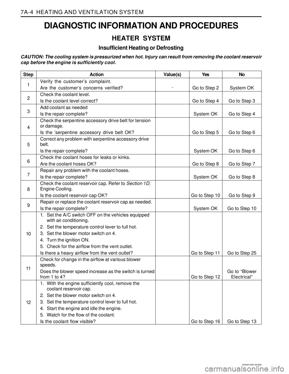
SSANGYONG MY2002
7A-4 HEATING AND VENTILATION SYSTEM
DIAGNOSTIC INFORMATION AND PROCEDURES
HEATER SYSTEM
Insufficient Heating or Defrosting
CAUTION: The cooling system is pressurized when hot. Injury can result from removing the coolant reservoir
cap before the engine is sufficiently cool.
Step
1
2
3
4
5
6
7
8
9
10
11
12
Action
Verify the customer’s complaint.
Are the customer’s concerns verified?
Check the coolant level.
Is the coolant level correct?
Add coolant as needed
Is the repair complete?
Check the serpentine accessory drive belt for tension
or damage.
Is the ’serpentine accessory drive belt OK?
Correct any problem with serpentine accessory drive
belt.
Is the repair complete?
Check the coolant hoses for leaks or kinks.
Are the coolant hoses OK?
Repair any problem with the coolant hoses.
Is the repair complete?
Check the coolant reservoir cap. Refer to Section 1D,
Engine Cooling.
Is the coolant reservoir cap OK?
Repair or replace the coolant reservoir cap as needed.
Is the repair complete?
1. Set the A/C switch OFF on the vehicles equipped
with air conditioning.
2. Set the temperature control lever to full hot.
3. Set the blower motor switch on 4.
4. Turn the ignition ON.
5. Check for the airflow from the vent outlet.
Is there a heavy airflow from the vent outlet?
Check for change in the airflow at various blower
speeds.
Does the blower speed increase as the switch is turned
from 1 to 4?
1. With the engine sufficiently cool, remove the
coolant reservoir cap.
2. Set the blower motor switch on 4.
3. Set the temperature control lever to full hot.
4. Start the engine and idle the engine.
5. Watch for the flow of the coolant.
Is the coolant flow visible?Yes
Go to Step 2
Go to Step 4
System OK
Go to Step 5
System OK
Go to Step 8
System OK
Go to Step 10
System OK
Go to Step 11
Go to Step 12
Go to Step 16No
System OK
Go to Step 3
Go to Step 4
Go to Step 6
Go to Step 6
Go to Step 7
Go to Step 8
Go to Step 9
Go to Step 10
Go to Step 25
Go to “Blower
Electrical”
Go to Step 13 Value(s)
-