1997 SSANGYONG KORANDO check engine light
[x] Cancel search: check engine lightPage 923 of 2053

HYDRAULIC BRAKES 4A-3
SSANGYONG MY2002
DIAGNOSTIC INFORMATION AND PROCEDURES
BRAKE SYSTEM TESTING
Brakes should be tested on a dry, clean, reasonably
smooth and level roadway. A true test of brake perfor-
mance cannot be made if the roadway is wet, greasy,
or covered with loose dirt which can cause tires not to
grip the road unequally. Testing also will be inaccurate
on a crowned roadway because the wheels tend to
bounce.
Test the brakes at different vehicle speeds with both
light-and heavy-pedal pressure; however, avoid locking
the brakes and sliding the tires. Locked brakes and
slid-ing tires do not indicate brake efficiency since
heavily braked but turning wheels will stop the vehicle
in less distance than locked brakes. More tire-to-road
friction is present with a heavily braked, turning tire
than with a sliding tire.
Because of the high deceleration capability, a firmer
pedal may be felt at higher deceleration levels.
There are three major external conditions that affect
brake performance:
•Tires having unequal contact and grip of the road
will cause unequal braking. Tires must be equally
inflated, and the tread pattern of the right and the
left tires must be approximately equal.
Unequal loading of the vehicle can affect the brake
performance since the most heavily loaded wheels
require more braking power, and thus more braking
effort, than the others.
Misalignment of the wheels, particularly conditions
of excessive camber and caster, will cause the
brakes to pull to one side.
To check for brake fluid leaks, hold constant foot pres-
sure on the pedal with the engine running at idle and
the shift lever in NEUTRAL. If the pedal gradually falls
away with the constant pressure, the hydraulic system
may be leaking. Perform a visual check to confirm any
suspected leaks.
Check the master cylinder fluid level. While a slight
drop in the reservoir level results from normal lining
wear, an abnormally low level indicates a leak in the
system. The hydraulic system may be leaking either
internally or externally. Refer to the procedure below
to check the master cylinder. The system may appear
to pass this test while still having a slight leak. If the
fluid level is normal, check the vacuum booster pushrod
length. If an incorrect pushrod length is found, adjust
or replace the rod.Check the master cylinder using the following proce
dure:
Check for a cracked master cylinder casting or a
brake fluid leak around the master cylinder. Leaks
are indicated only if there is at least one drop of
fluid. A damp condition is not abnormal.
Check for a binding pedal linkage and for an
incorrect pushrod length. If both of these parts are
in satisfactory condition, disassemble the master
cylinder and check for an elongated or swollen
primary cylinder or piston seals. If swollen seals
are found, substandard or contaminated brake fluid
should be suspected. If contaminated brake fluid
is found, all the components should be
disassembled and cleaned, and all the rubber
components should be replaced. All of the pipes
must also be flushed.
Improper brake fluid, or mineral oil or water in the fluid,
may cause the brake fluid to boil or cause deterioration
of the rubber components. If the primary piston cups in
the master cylinder are swollen, the rubber parts have
deteriorated.
If deterioration of the rubber is evident, disassemble
all the hydraulic parts and wash the parts with alcohol.
Dry these parts with compressed air before reassembly
to keep the alcohol out of the system. Replace all the
rubber parts in the system, including the hoses. When
working on the brake mechanisms, check for fluid on
the linings. If excessive fluid is found, replace the
linings.
If the master cylinder piston seals are in satisfactory
condition, check for leaks or excessive heat conditions.
If these conditions are not found, drain the fluid, flush
the master cylinder with brake fluid, refill the master
cylinder, and bleed the system.
BRAKE HOSE INSPECTION
The hydraulic brake hoses should be inspected at least
twice a year. The brake hose assembly should be
checked for road hazard damage, cracks, chafing of
the outer cover, and for leaks or blisters. Inspect the
hoses for proper routing and mounting. A brake hose
that rubs on a suspension component will wear and
eventually fail. A light and a mirror may be needed for
an adequate inspection. If any of the above conditions
are observed on the brake hose, adjust or replace the
hose as necessary.
Page 1089 of 2053
SSANGYONG MY2002
4G-2 PARKING BRAKE
DESCRIPTION AND OPERATION
BRAKE CALIPER
This braking system uses a BRAKE warning light lo-
cated in the instrument panel cluster.
The following conditions will activate the BRAKE lamp:
•The parking brake is applied when the ignition is
ON. The lamp will turn off when the parking brake
is released.
The fluid level is below the minimum mark in the
master cylinder reservoir. The lamp will turn off when
the fluid level is above the minimum.
As a test of the lamp circuit, the BRAKE lamp will
glow dimly when the ignition is ON, even if the
parking brake is off and fluid level is above the
minimum. The lamp will turn off when the engine is
started. When the brake is firmly applied, the parking
brake should hold the vehicle with ample pedal
travel remaining.
Check for frayed cables, rust, etc. or any condition
that may inhibit present (or future) free movement of
the parking brake lever assembly.
Page 1133 of 2053
AUTOMATIC TRANSMISSION 5A-39
SSANGYONG MY2002
4. Place a fluid container below the fluid filler plug.
5. Clean all dirt from around the fluid filler plug.
Remove the fluid filler plug. Clean the filler plug
and check that there is no damage to the ‘O’ ring.
If fluid drains through the filler hole the transmis-
sion may have been overfilled. When the fluid
stops draining the fluid level is correct. Install
the fluid filler plug and tighten it to 33 Nm (24
lb-ft).
If fluid does not drain through the filler hole, the
transmission fluid level may be low. Install the
filler pump into the filler hole. Lower the vehicle
with the filler pump still connected and partially
fill the fluid through the filler hole.
Start the vehicle in P (Park) with the parking
brake and the brake applied. With the engine
idling, move the gear shift. control lever through
the gear ranges, pausing a few seconds in each
range and adding the fluid until gear application
is felt.
Return the gear shift lever to P (Park).
Turn the engine OFF and raise the vehicle. When
the three minutes passed after the engine
stopped, remove the filler pump.
Check if the fluid level is aligned with the bottom
of the filler hole. If not, add a small quantity of
fluid to the correct level. Install the fluid filler
plug and tighten it to 33 Nm (24 lb-ft).
If fluid does not drain through the filler hole al-
though adding a total of 1.5 liters, the transmission
should be inspected for fluid leaks and any leaks
should be fixed before setting the transmission
fluid level.
6. When the fluid level checking procedure is com-
pleted, wipe any fluid around the filler plug with a
rag or shop towel.
Fluid Level Set After Service
1. Depending on the service procedure performed,
add the following amounts of fluid through the filler
plug hole prior to adjusting the fluid level:
Converter empty 8.0 liters (8.5 quarts)
Converter full 3.8 liters (4.0 quarts)
2. Follow steps 1 through 4 of the Fluid Level Diagnosis
Procedure.
3. Clean all dirt from around the fluid filler plug.
Remove the fluid filler plug. Clean the filler plug
and check that there is no damage to the ‘O’ ring.
4. Lower the vehicle with the filler pump still connected
and start the vehicle in P (Park) with the parking
brake and the brake applied. With the engine idling,
move the gear shift control lever through the gear
ranges, pausing a few seconds in each range and
adding the fluid until gear application is felt.Then add an additional 0.5 litres of fluid. Return
the gear shift lever to P (Park). Turn the engine OFF
and raise the vehicle. Install the fluid filler plug and
tighten it to 33 Nm (24 lb-ft).
5. Drive the vehicle at 3.5 to 4.5 kilometers with light
throttle so that the engine does not exceed 2500
rpm.
This should result in the transmission temperature
being in the range 50 - 60 °C (82 - 140 °F). With the
brake applied, move the shift lever through the gear
ranges, pausing a few seconds in each range at
the engine idling.
6. Return the gear shift lever to P (Park).
Turn the en-gine OFF and raise the vehicle on the
hoist, if applicable, ensuring the vehicle is level.
When the three minutes passed after the engine
stopped, remove the filler plug.
Check if the fluid level is aligned with the bottom of
the filler hole. If not, add a small quantity of fluid to
the correct level. Install the fluid filler plug and
tighten it to 33 Nm (24 lb-ft).
7. Wipe any fluid around the filler plug with a rag or
shop towel.
FLUID LEAK DIAGNOSIS AND
REPAIR
The cause of most external leaks can generally be lo-
cated and repaired with the transmission in the vehicle.
Methods for Locating Leaks
General Method
1. Verify that the leak is transmission fluid.
2. Thoroughly clean the suspected leak area.
3. Drive the vehicle for approximately 25 km (15 miles)
or until the transmission reaches normal operating
temperature (88 °C, 190 °F).
4. Park the vehicle over clean paper or cardboard.
5. Turn the engine OFF and look for fluid spots on the
paper.
6. Make the necessary repairs to correct the leak.
Powder Method
1. Thoroughly clean the suspected leak area.
2. Apply an aerosol type powder (foot powder) to the
suspected leak area.
3. Drive the vehicle for approximately 25 km (15 miles)
or until the transmission reaches normal operating
temperature (88 °C, 190 °F).
4. Turn the engine OFF.
5. Inspect the suspected leak area and trace the leak
path through the powder to find the source of the
leak.
6. Make the necessary repairs.
Page 1134 of 2053
5A-40 AUTOMATIC TRANSMISSION
SSANGYONG MY2002
Dye and Black Light Method
1. Add dye to the transmission through the transmission
fluid filler plug. Follow the manufacturer’s recommen-
dation for the amount of dye to be used.
2. Use the black light to find the fluid leak.
3. Make the necessary repairs.
Repairing the Fluid Leak
Once the leak point is found the source of the leak
must be determined. The following list describes the
potential causes for the leak:
Fasteners are not torqued to specification.
Fastener threads and fastener holes are dirty or
corroded.
Gaskets, seals or sleeves are misaligned, damaged
or worn.
Damaged, warped or scratched seal bore or gasket
surface.
Loose or worn bearing causing excess seal or sleeve
wear.
Case or component porosity.
Fluid level is too high.
Plugged vent or damaged vent tube.
Water or coolant in fluid.
Fluid drain back holes plugged.
ELECTRICAL / GARAGE SHIFT
TEST
This preliminary test should be performed before a hoist
or road test to make sure electronic control inputs are
connected and operating. If the inputs are not checked
before operating the transmission, a simple electrical
condition could be misdiagnosed as a major
transmission condition.
A scan tool provides valuable information and must
be used on the automatic transmission for accurate
diagnosis.
1. Move gear shift control lever to P (Park) and set
the parking brake.
2. Connect scan tool to Data Link Connector (DLC)
terminal.
3. Start engine.
4. Turn the scan tool ON.
5. Verify that the appropriate signals are present.
These signals may include:
ENGINE SPEED
VEHICLE SPEED
THROTTLE POSITION
ACCEL. PEDAL POSITION
TRANSMISSION GEAR STATE
GEAR SHIFT LEVER POSITION
TRANSMISSION FLUID TEMPERATURE
CLOSED THROTTLE POSITION LEARN
OPEN THROTTLE POSITION LEARNT
CLOSED ACCEL. PEDAL POSITION LEARNT
OPEN ACCEL. PEDAL POSITION LEARNT
A/C COMPRESSOR STATUS
KICKDOWN SWITCH STATUS
4WD STATUS
MODE SWITCH
THROTTLE POSITION VOLTAGE
GEAR SHIFT LEVER POSITION VOLTAGE
TRANS. FLUID TEMPERATURE VOLTAGE
A/C SWITCH
KICKDOWN SWITCH VOLTAGE
4WD LAMP LOW VOLTAGE
4WD LAMP HIGH VOLTAGE
MODE SWITCH VOLTAGE
BATTERY VOLTAGE
6. Monitor the A/C COMPRESSOR STATUS signal
while pushing the A/C switch.
The A/C COMPRESSOR STATUS should come
ON when the A/C switch is pressed, and turn
OFF when the A/C switch is repushed.
7. Monitor the GEAR SHIFT LEVER POSITION signal
and move the gear shift control lever through all
the ranges.
Verify that the GEAR SHIFT LEVER POSITION
value matches the gear range indicated on the
instrument panel or console.
Gear selections should be immediate and not
harsh.
8. Move gear shift control lever to neutral and monitor
the THROTTLE POSITION signal while increasing
and decreasing engine speed with the accelerator
pedal.
THROTTLE POSITION should increase with en-
gine speed.
ROAD TEST PROCEDURE
Perform the road test using a scan tool.
This test should be performed when traffic and road
conditions permit.
Observe all traffic regulations.
ELECTRONIC ADJUSTMENTS
Idle Speed Adjustments
Carry out the adjustments to the idle speed as detailed
in the workshop manual.
Vehicle Coding
The vehicle coding is integrated as part of the
diagnostic software. A scan tool has the function to
code the ve-hicle through the K-line.
Page 1135 of 2053
5A-40 AUTOMATIC TRANSMISSION
SSANGYONG MY2002
Dye and Black Light Method
1. Add dye to the transmission through the transmission
fluid filler plug. Follow the manufacturer’s recommen-
dation for the amount of dye to be used.
2. Use the black light to find the fluid leak.
3. Make the necessary repairs.
Repairing the Fluid Leak
Once the leak point is found the source of the leak
must be determined. The following list describes the
potential causes for the leak:
Fasteners are not torqued to specification.
Fastener threads and fastener holes are dirty or
corroded.
Gaskets, seals or sleeves are misaligned, damaged
or worn.
Damaged, warped or scratched seal bore or gasket
surface.
Loose or worn bearing causing excess seal or sleeve
wear.
Case or component porosity.
Fluid level is too high.
Plugged vent or damaged vent tube.
Water or coolant in fluid.
Fluid drain back holes plugged.
ELECTRICAL / GARAGE SHIFT
TEST
This preliminary test should be performed before a hoist
or road test to make sure electronic control inputs are
connected and operating. If the inputs are not checked
before operating the transmission, a simple electrical
condition could be misdiagnosed as a major
transmission condition.
A scan tool provides valuable information and must
be used on the automatic transmission for accurate
diagnosis.
1. Move gear shift control lever to P (Park) and set
the parking brake.
2. Connect scan tool to Data Link Connector (DLC)
terminal.
3. Start engine.
4. Turn the scan tool ON.
5. Verify that the appropriate signals are present.
These signals may include:
ENGINE SPEED
VEHICLE SPEED
THROTTLE POSITION
ACCEL. PEDAL POSITION
TRANSMISSION GEAR STATE
GEAR SHIFT LEVER POSITION
TRANSMISSION FLUID TEMPERATURE
CLOSED THROTTLE POSITION LEARN
OPEN THROTTLE POSITION LEARNT
CLOSED ACCEL. PEDAL POSITION LEARNT
OPEN ACCEL. PEDAL POSITION LEARNT
A/C COMPRESSOR STATUS
KICKDOWN SWITCH STATUS
4WD STATUS
MODE SWITCH
THROTTLE POSITION VOLTAGE
GEAR SHIFT LEVER POSITION VOLTAGE
TRANS. FLUID TEMPERATURE VOLTAGE
A/C SWITCH
KICKDOWN SWITCH VOLTAGE
4WD LAMP LOW VOLTAGE
4WD LAMP HIGH VOLTAGE
MODE SWITCH VOLTAGE
BATTERY VOLTAGE
6. Monitor the A/C COMPRESSOR STATUS signal
while pushing the A/C switch.
The A/C COMPRESSOR STATUS should come
ON when the A/C switch is pressed, and turn
OFF when the A/C switch is repushed.
7. Monitor the GEAR SHIFT LEVER POSITION signal
and move the gear shift control lever through all
the ranges.
Verify that the GEAR SHIFT LEVER POSITION
value matches the gear range indicated on the
instrument panel or console.
Gear selections should be immediate and not
harsh.
8. Move gear shift control lever to neutral and monitor
the THROTTLE POSITION signal while increasing
and decreasing engine speed with the accelerator
pedal.
THROTTLE POSITION should increase with en-
gine speed.
ROAD TEST PROCEDURE
Perform the road test using a scan tool.
This test should be performed when traffic and road
conditions permit.
Observe all traffic regulations.
ELECTRONIC ADJUSTMENTS
Idle Speed Adjustments
Carry out the adjustments to the idle speed as detailed
in the workshop manual.
Vehicle Coding
The vehicle coding is integrated as part of the
diagnostic software. A scan tool has the function to
code the ve-hicle through the K-line.
Page 1152 of 2053
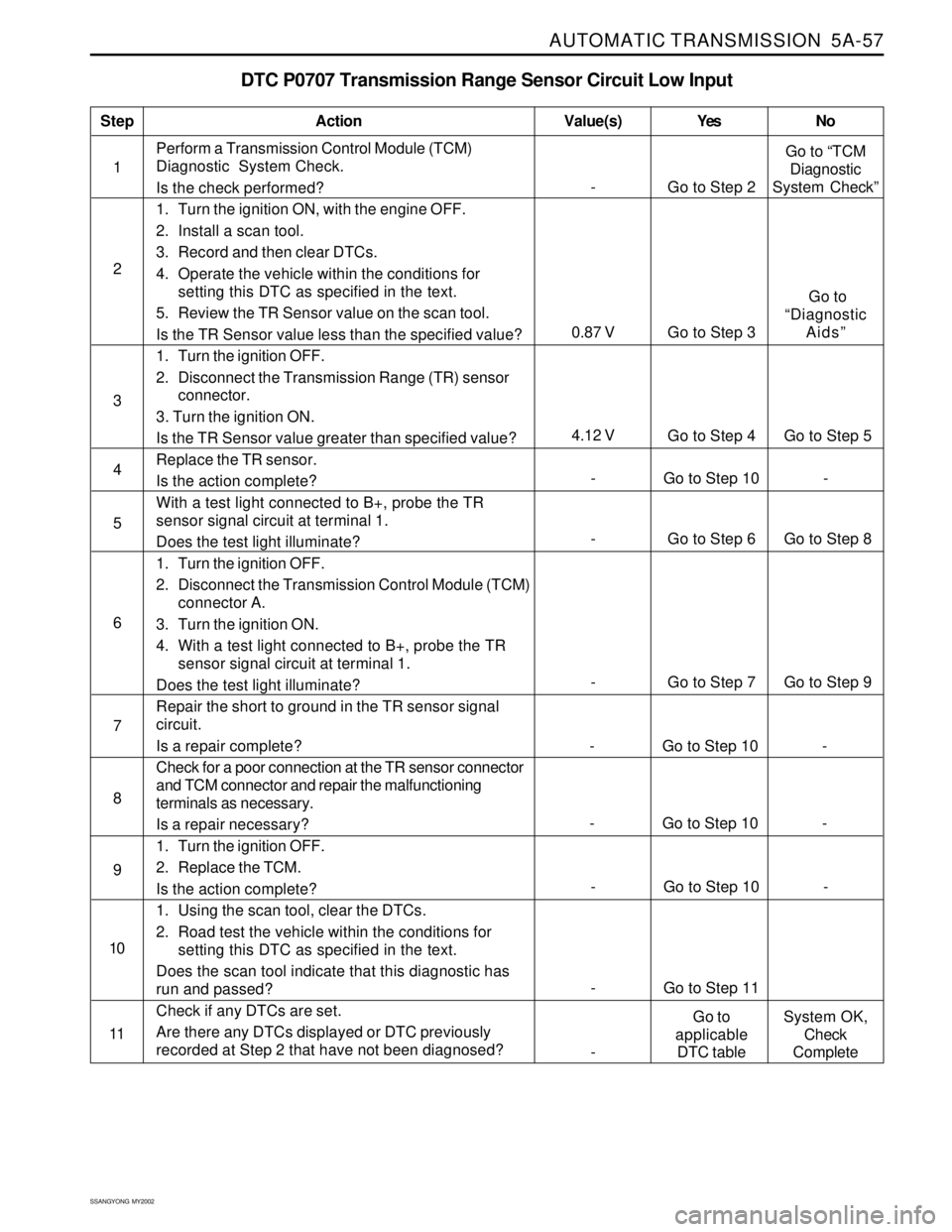
AUTOMATIC TRANSMISSION 5A-57
SSANGYONG MY2002
DTC P0707 Transmission Range Sensor Circuit Low Input
1Perform a Transmission Control Module (TCM)
Diagnostic System Check.
Is the check performed?
1. Turn the ignition ON, with the engine OFF.
2. Install a scan tool.
3. Record and then clear DTCs.
4. Operate the vehicle within the conditions for
setting this DTC as specified in the text.
5. Review the TR Sensor value on the scan tool.
Is the TR Sensor value less than the specified value?
1. Turn the ignition OFF.
2. Disconnect the Transmission Range (TR) sensor
connector.
3. Turn the ignition ON.
Is the TR Sensor value greater than specified value?
Replace the TR sensor.
Is the action complete?
With a test light connected to B+, probe the TR
sensor signal circuit at terminal 1.
Does the test light illuminate?
1. Turn the ignition OFF.
2. Disconnect the Transmission Control Module (TCM)
connector A.
3. Turn the ignition ON.
4. With a test light connected to B+, probe the TR
sensor signal circuit at terminal 1.
Does the test light illuminate?
Repair the short to ground in the TR sensor signal
circuit.
Is a repair complete?
Check for a poor connection at the TR sensor connector
and TCM connector and repair the malfunctioning
terminals as necessary.
Is a repair necessary?
1. Turn the ignition OFF.
2. Replace the TCM.
Is the action complete?
1. Using the scan tool, clear the DTCs.
2. Road test the vehicle within the conditions for
setting this DTC as specified in the text.
Does the scan tool indicate that this diagnostic has
run and passed?
Check if any DTCs are set.
Are there any DTCs displayed or DTC previously
recorded at Step 2 that have not been diagnosed?
StepAction Value(s) Yes No
2
3
- Go to Step 6 Go to Step 8 5
- Go to Step 7 Go to Step 9 6
- Go to Step 10 - 4
7
- Go to Step 10 - 8
- Go to Step 10 - 9
- Go to Step 11 10
11
- Go to Step 2Go to “TCM
Diagnostic
System Check”
4.12 V
Go to Step 4 Go to Step 5
0.87 V Go to Step 3 Go to
“Diagnostic
Aids”
-Go to
applicable
DTC tableSystem OK,
Check
Complete
- Go to Step 10 -
Page 1154 of 2053
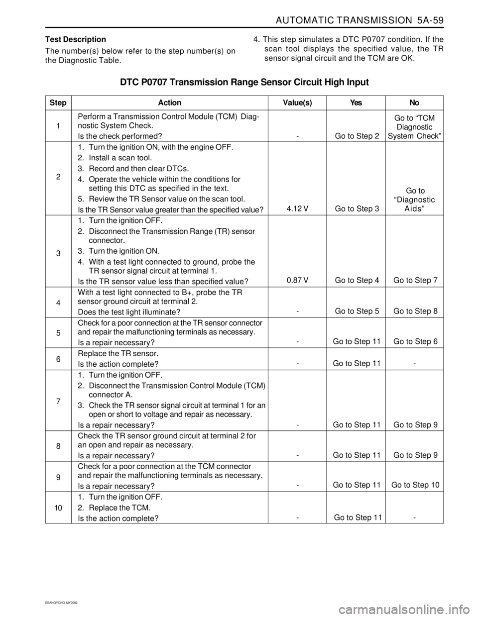
AUTOMATIC TRANSMISSION 5A-59
SSANGYONG MY2002
Test Description
The number(s) below refer to the step number(s) on
the Diagnostic Table.4. This step simulates a DTC P0707 condition. If the
scan tool displays the specified value, the TR
sensor signal circuit and the TCM are OK.
DTC P0707 Transmission Range Sensor Circuit High Input
1Perform a Transmission Control Module (TCM) Diag-
nostic System Check.
Is the check performed?
1. Turn the ignition ON, with the engine OFF.
2. Install a scan tool.
3. Record and then clear DTCs.
4. Operate the vehicle within the conditions for
setting this DTC as specified in the text.
5. Review the TR Sensor value on the scan tool.
Is the TR Sensor value greater than the specified value?
1. Turn the ignition OFF.
2. Disconnect the Transmission Range (TR) sensor
connector.
3. Turn the ignition ON.
4. With a test light connected to ground, probe the
TR sensor signal circuit at terminal 1.
Is the TR sensor value less than specified value?
With a test light connected to B+, probe the TR
sensor ground circuit at terminal 2.
Does the test light illuminate?
Check for a poor connection at the TR sensor connector
and repair the malfunctioning terminals as necessary.
Is a repair necessary?
Replace the TR sensor.
Is the action complete?
1. Turn the ignition OFF.
2. Disconnect the Transmission Control Module (TCM)
connector A.
3. Check the TR sensor signal circuit at terminal 1 for an
open or short to voltage and repair as necessary.
Is a repair necessary?
Check the TR sensor ground circuit at terminal 2 for
an open and repair as necessary.
Is a repair necessary?
Check for a poor connection at the TCM connector
and repair the malfunctioning terminals as necessary.
Is a repair necessary?
1. Turn the ignition OFF.
2. Replace the TCM.
Is the action complete?
StepAction Value(s) Yes No
2
3
- Go to Step 11 Go to Step 6 5
- Go to Step 11 - 6
- Go to Step 5 Go to Step 8 4
- Go to Step 11 Go to Step 9 7
- Go to Step 11 Go to Step 9 8
- Go to Step 11 Go to Step 10 9
10
- Go to Step 2Go to “TCM
Diagnostic
System Check”
0.87 V Go to Step 4 Go to Step 7
4.12 V Go to Step 3 Go to
“Diagnostic
Aids”
- Go to Step 11 -
Page 1158 of 2053
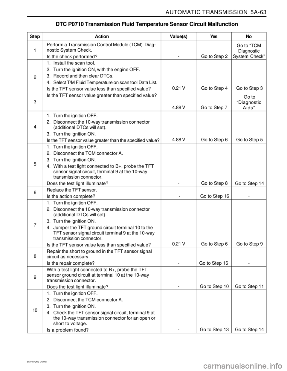
AUTOMATIC TRANSMISSION 5A-63
SSANGYONG MY2002
DTC P0710 Transmission Fluid Temperature Sensor Circuit Malfunction
1Perform a Transmission Control Module (TCM) Diag-
nostic System Check.
Is the check performed?
1. Install the scan tool.
2. Turn the ignition ON, with the engine OFF.
3. Record and then clear DTCs.
4. Select T/M Fluid Temperature on scan tool Data List.
Is the TFT sensor value less than specified value?
Is the TFT sensor value greater than specified value?
1. Turn the ignition OFF.
2. Disconnect the 10-way transmission connector
(additional DTCs will set).
3. Turn the ignition ON.
Is the TFT sensor value greater than the specified value?
1. Turn the ignition OFF.
2. Disconnect the TCM connector A.
3. Turn the ignition ON.
4. With a test light connected to B+, probe the TFT
sensor signal circuit, terminal 9 at the 10-way
transmission connector.
Does the test light illuminate?
Replace the TFT sensor.
Is the action complete?
1. Turn the ignition OFF.
2. Disconnect the 10-way transmission connector
(additional DTCs will set).
3. Turn the ignition ON.
4. Jumper the TFT ground circuit terminal 10 to the
TFT sensor signal circuit terminal 9 at the 10-way
transmission connector.
Is the TFT sensor value less than specified value?
Repair the short to ground in the TFT sensor signal
circuit as necessary.
Is the repair complete?
With a test light connected to B+, probe the TFT
sensor ground circuit at terminal 10 at the 10-way
transmission connector.
Does the test light illuminate?
1. Turn the ignition OFF.
2. Disconnect the TCM connector A.
3. Turn the ignition ON.
4. Check the TFT sensor signal circuit, terminal 9 at
the 10-way transmission connector for an open or
short to voltage.
Is a problem found?
StepAction Value(s) Yes No
2
3
- Go to Step 8
Go to Step 14 5
- Go to Step 16
- 6 4
7
0.21 V Go to Step 6 Go to Step 9
8
9
- Go to Step 2Go to “TCM
Diagnostic
System Check”
0.21 V Go to Step 4 Go to Step 3
4.88 V Go to Step 7 Go to
“Diagnostic
Aids”
10
- Go to Step 13 Go to Step 14
- Go to Step 10 Go to Step 11
- Go to Step 16 -
4.88 V Go to Step 6 Go to Step 5